Language selection

Search

Patent 2094342 Summary

Third-party information liability

Some of the information on this Web page has been provided by external sources. The Government of Canada is not responsible for the accuracy, reliability or currency of the information supplied by external sources. Users wishing to rely upon this information should consult directly with the source of the information. Content provided by external sources is not subject to official languages, privacy and accessibility requirements.

Claims and Abstract availability

Any discrepancies in the text and image of the Claims and Abstract are due to differing posting times. Text of the Claims and Abstract are posted:

  • At the time the application is open to public inspection;
  • At the time of issue of the patent (grant).
(12) Patent: (11) CA 2094342
(54) English Title: APPARATUS FOR LIFTING AND DUMPING A RECEPTACLE
(54) French Title: DISPOSITIF POUR SOULEVER ET VIDER UN RECEPTACLE
Status: Expired
Bibliographic Data
(51) International Patent Classification (IPC):
  • B65F 3/04 (2006.01)
  • B65F 3/02 (2006.01)
(72) Inventors :
  • OSBORN, WARREN (United States of America)
(73) Owners :
  • OSBORN, WARREN (United States of America)
(71) Applicants :
(74) Agent: MACRAE & CO.
(74) Associate agent:
(45) Issued: 1999-01-12
(22) Filed Date: 1993-04-19
(41) Open to Public Inspection: 1993-10-31
Examination requested: 1995-10-10
Availability of licence: N/A
(25) Language of filing: English

Patent Cooperation Treaty (PCT): No

(30) Application Priority Data:
Application No. Country/Territory Date
876,321 United States of America 1992-04-30

Abstracts

English Abstract


The apparatus of the present invention uses fluid motor driven
rotating hooks mounted within the rear opening of a refuse collection
vehicle. These hooks grasp and lift dumpsters by their trunnion bars
and pull them into the vehicle. Following the initial hook motion, a
lever pivots upwardly to invert the receptacle and empty its contents.
In another feature, there is provided an accessory for attachment to
the rotating hooks for grasping and dumping smaller containers. This
device uses a cam-actuated mechanism that operates during initial
rotation of the hooks. The cam actuates linkage which grasps the lower
handle of the container and the complete rotation of the hooks inverts
the container.


French Abstract

Cette invention concerne un appareil à crochets pivotants entraîné par moteur hydraulique et monté dans l'ouverture arrière d'un camion à ordures. Ces crochets soulèvent les bennes à ordures par leurs tourillons pour ensuite les entraîner à l'intérieur de la caisse du camion. Après le déplacement initial des crochets, un levier pivote vers le haut pour renverser la benne et la vider de son contenu. L'appareil est également équipé d'un accessoire à monter sur le crochets pour la manutention de contenants à ordures plus petits que les bennes précitées. Cet accessoire fait appel à un mécanisme à came qui intervient lors du pivotement initial des crochets pour actionner une tringlerie qui saisit la poignée inférieure du contenant dont l'inversion est automatique en fin de pivotement des crochets.

Claims

Note: Claims are shown in the official language in which they were submitted.


THE EMBODIMENTS OF THE INVENTION IN WHICH AN EXCLUSIVE
PROPERTY OR PRIVILEGE IS CLAIMED ARE DEFINED AS FOLLOWS:

1. An apparatus for a refuse collection vehicle having
a rear opening thereto for dumping a receptacle; said
receptacle having contents therein to be dumped into said
refuse collection vehicle; said receptacle further having a
top, a front, and a pair of oppositely disposed sides with bar
members being receivable within said rear opening and
extending outwardly from said sides adjacent to said top and
said front of said receptacle, said apparatus comprising:
a pair of selectively rotatable hook members being
mounted on a coextensive axis and oppositely disposed within
said rear opening of said refuse gathering vehicle at each
side thereof and providing a cam actuation for inverting said
receptacle;
means for selectively causing rotation of said hook
members, whereby said bars extending from said receptacle are
engaged by said rotatable hook members, thereby causing said
receptacle to be pulled forward of and lower than said
coextensive axis into said rear opening;
means for elevating and rotating said receptacle;
wherein
said means for completing a rotation of said
receptacle comprises a lever member;
said lever member is pivotally mounted to said
vehicle beneath said rear opening; and


said lever member and said hook members cooperate to
invert said receptacle forward of and lower than said
coextensive axis, whereby said contents of said receptacle may
be substantially received within said rear opening.
2. The apparatus of claim 1 wherein said hook members
are driven by fluid powered motors.
3. The apparatus of claim 1 wherein said lever member
is pivoted by fluid piston and cylinder means.
4. The apparatus of claim 1 wherein said hook members
are driven by fluid powered motors; said means for elevating
and rotating said receptacle comprises said lever member
pivotally mounted to said vehicle beneath said rear opening
and pivoted by fluid piston and cylinder means; and further
comprising means to sense the rotation of said hook members
and to actuate said lever member subsequent to said rotation
of said hook members.
5. In an apparatus for dumping a receptacle into a
refuse collection vehicle comprising:
said refuse collection vehicle having a rear opening
therein;
said receptacle having contents to be dumped into
said collection vehicle;
said receptacle further having a top, a front, and
a pair of oppositely disposed sides with a first bar member
and a second bar member being receivable within said rear
opening;


said first bar member and said second bar member
being oppositely disposed and extending outwardly from said
sides adjacent to said top and said front of said receptacle;
and
said apparatus further comprising a first means for
elevating said receptacle:
the improvement comprising:
a first selectively rotatable hook member and a
second selectively rotatable hook member being mounted on a
coextensive axis and oppositely disposed within said rear
opening of said refuse gathering vehicle at each side thereof
in order to provide a cam actuation for inverting said
receptacle;
said cam actuation causing said receptacle to be
elevated, drawn forward and rotated down into a locked
position, thereby pivoting said receptacle over said rear
opening and forward of and lower than said coextensive axis;
said first selectively rotatable hook member and
said second selectively rotatable hook member being spaced
apart;
means for engaging said first bar member with said
first hook member and said second bar member with said second
hook member;
means for pulling said receptacle into said rear
opening;


means for selectively causing rotation of said first
hook member and said second hook member; and
said first means for elevating said receptacle
cooperating with said first hook member and said second hook
member to invert said receptacle, pulling said receptacle
forward of and lower than said coextensive axis, whereby said
contents of said receptacle may be substantially received
within said rear opening.
6. The apparatus of claim 5 wherein said first means
for elevating said receptacle comprises a lever member
pivotally mounted to said vehicle beneath said rear opening.
7. The apparatus of claim 5 wherein:
said hook-members are driven by fluid powered
motors;
said first means for elevating said receptacle
comprises a lever member being pivotally mounted to said
vehicle beneath said rear opening and pivoted by fluid piston
and cylinder means; and
means to sense a rotational position of said hook
members and to actuate said lever member subsequent to said
rotation of said hook members.


Description

Note: Descriptions are shown in the official language in which they were submitted.


APPARATUS FOR LIF~ING AND DUMPING A RECEPTACLE


BACKGROUND OF THE INVEN~ION
Field of the Invention
S Tllis invention rel~tes to apparatus for lifting and ~umping a
recep~acle during trash collection. More particularly this invention
relates to apparatus for efEiciently dumping a container, such as a
dumpster, into a refuse gathering vehicle having a rear opening.


10 Description of the Prior Art
Lar~e receptacles, generally referred to as dumpsters, have been
clifficult to efficiently dump into refuse collection vehicles. These
dumpsters present laterally e~tending bar members (referred to as
trlmnion bars) from their upper front, and these bars are used to grasp,
15 lift and dump the container in cooperation with a lower foot member.
Prior systems have generally required operator inte~vention to attach the
dumpster to the lifting apparatus. Chains are extended from the vehicle
to hook onto the trunnion bars, and re~raction of the chains pulls the
dumpster into the vehicle cavity.


,

2 ~ 3 4 2
SUMMARY OF THE INVEN~ION


Accordingly, it is a principal objective of the present invention to
prov;de an effective dumping apparatus which allows automatic grasping
S and inYersion of the dumpster without operal;or ineerverltion.
The apparatus of the present invention usès rotating hooks mounted
within the rear opening of the vehicle ancl e~tending outwardly
therefrom. Rotation of the hooks engage the trunnion bars of the
dumpster such that the receptacle is lifted and pulled into the opening
10 by the hooks. Following the initial hook motion, a lower foot pivots
upwardly to complete the inversion of the receptacle and empty its
contents.
In allother ~eature, there is provided an accessory for attachment to
the rotating hooks ~or grasping and dumping smaller containers. This
15 device uses a cam-actuated mechanism that operates as the hooks rotate.
The cam ~ctll~tes linkage which operates to grasp the lower hanclles of
this container during movement into the rear opening. Complete
rotation of ~e hooks completes the in~ersion of ~he container.


, . . -
.. . . .

3 2 ~
BRIEF DES(: RI~:'TION OF THE D:RAWINGS


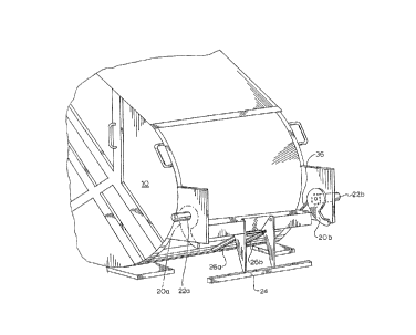
Figure 1 is a pictorial view of a receptacle dumpillg apparatus in
accordance with the present irlvention.
S Figure 2 is a side elevational view of the apparatus of Figure 1
showing the scquence of the duillping operation.
Figure 3 is a side view of ~n attachment device for the apparatus of
Figure 1 for dumping smaller ~ontainers.
Figure 4 is a pictorial view of the cam actuation of the device o~
10 Figure 3. :
While the inventioll w;ll be described in connection with a preferred
embodimen~, it will be understood that it is not the intent to limit the
invention to that embodiment. On the contrary, it is the intent to cover
all alternatives, modifications, and equivalents as may be included within
15 the spirit and scope of the invention as defined by the appended claims.


.

3 ~ ~
DESCRIPIION OF THE~ PREFERRED :~MBODIMENT


Turning first to F;gure 1 there is shown a cvmmonly known refuse
collection vehic}e 10 having a rear opening thereto. Mounted for
S rotation on the inside wall on each side are hook members 20a and 20b.
These members are eccentrically mounted with an elongated hook
extending therefrom. Selective rotation of the hooks are accomplished
by use of fluid motors 22a and 22b connected to the hydraulic lines of
the vehicle. Additionally, a lower foot member 24 is pivo~ally mounted
10 to the lip of the rear opening and driven by fluidic cylinders 26a and
26b to complete tlle inversion of the dumpster as described in detail
below.
The refuse collection vehicle is first moved into contact with the
dumpster, allowing the hook members 20a and 20b to extend under the
15 trunnion bars 32 extending from the dumpster. Fluid power is then
applied to the fluid motors 22a and 22_ causing the hooks to rotate
This rotation initially lifts the dumpster (posihon 34a), tl:len draws the
dumpster into the vehicle opening ~position 34b), positioning the
trunnion bars against the stop 36. At this point the rotational position
20 of the hooks is sensed and the fluid power is directed to the cylinders
26a and 26k to drive the foot 24 upward agamst the dumpster and to
ultimately invert it (position 34c). I~e hydraulic circuitry to accomplish


.; : - - . .

- . ~ . . . .
- . .

.~ . . . . . . ~ . . - .

s '~9~2
the above actuation is not specified herein as it is well within the
capabilitiPs of one skilled in the art.
Turning now to Figures 3 and 4, there is shown an attachment to
the hook mechanism of Figure 1 to ~acilitate lifting and dumping of
S smaller containers 40. This at~achment employs a mountirlg bar 42
spanning the rear openillg Qf the vehiele and (remoYeably) secured to
the hook members 20a and 20b. An actuat:ing bar 44 extends along the
upper surface of the mounting bar and carries a pawl 46 at its extremi~
positioned to ride against a cam 48 secured to the side of the vehicle
10 opening. Ihe other end of the actuating bar 44 passes through a
bearing mount 50 (Figure 3~ and is affi:xed to an actuating lever 52.
~is lever in turn controls linlcage 54a and 54b irl response to rotation
of the actuating bar.
Operation of the linkage occurs when the hook members are driver
15 by the fluid motors as previously ~escribed. As rotation begins, the
pawl 46 contacts the cam 48 and is forced to rotate downwardly as
shown~ This rotation forces actuating lever 52 ~Figure 3) to pull
upwardly on the linkage 54a, to force linkage 54b to rotate about its
pivot 56~ As a result, the latch 58 closes over the lower handle 60 o~
20 the container to restrain it against the lower support 61. At the top of
~he container, the upper handle 62 is cradled by a support 64.
When the hooks 20a and 20b are rotated, the handies of the
container are grasped secnrely by the supports and by operation of the


6 2~9~3~ ~
linkage while the apparatus is rotated to initially position the container
into the dumpster. ~urther rotation ot the hook members completes the
;nversion o~ ~he container to dump its conten~s into ~he vehicle cavity.
From the foregoing description, it will be apparent that modifications
S can be made to the apparatus and method for using same without
departing from the te~.hinE.~ of the presellt invention. Accordingly, the

scope of the invention is only to be limited as necessit~ted by the
accompanying claims.


:


.

: ~

Representative Drawing
A single figure which represents the drawing illustrating the invention.
Administrative Status

For a clearer understanding of the status of the application/patent presented on this page, the site Disclaimer , as well as the definitions for Patent , Administrative Status , Maintenance Fee  and Payment History  should be consulted.

Administrative Status

Title Date
Forecasted Issue Date 1999-01-12
(22) Filed 1993-04-19
(41) Open to Public Inspection 1993-10-31
Examination Requested 1995-10-10
(45) Issued 1999-01-12
Expired 2013-04-19

Abandonment History

There is no abandonment history.

Payment History

Fee Type Anniversary Year Due Date Amount Paid Paid Date
Application Fee $0.00 1993-04-19
Maintenance Fee - Application - New Act 2 1995-04-19 $50.00 1995-01-27
Maintenance Fee - Application - New Act 3 1996-04-19 $50.00 1996-01-23
Maintenance Fee - Application - New Act 4 1997-04-21 $50.00 1997-01-29
Maintenance Fee - Application - New Act 5 1998-04-20 $75.00 1997-12-24
Final Fee $150.00 1998-09-22
Maintenance Fee - Patent - New Act 6 1999-04-19 $75.00 1999-01-27
Maintenance Fee - Patent - New Act 7 2000-04-19 $75.00 2000-03-15
Maintenance Fee - Patent - New Act 8 2001-04-19 $75.00 2001-02-12
Maintenance Fee - Patent - New Act 9 2002-04-19 $75.00 2002-03-20
Maintenance Fee - Patent - New Act 10 2003-04-21 $100.00 2003-01-17
Maintenance Fee - Patent - New Act 11 2004-04-19 $125.00 2004-02-25
Maintenance Fee - Patent - New Act 12 2005-04-19 $125.00 2005-01-27
Maintenance Fee - Patent - New Act 13 2006-04-19 $125.00 2005-12-22
Maintenance Fee - Patent - New Act 14 2007-04-19 $125.00 2007-01-23
Maintenance Fee - Patent - New Act 15 2008-04-21 $225.00 2008-01-31
Maintenance Fee - Patent - New Act 16 2009-04-20 $225.00 2009-01-21
Maintenance Fee - Patent - New Act 17 2010-04-19 $225.00 2010-01-20
Maintenance Fee - Patent - New Act 18 2011-04-19 $225.00 2011-01-27
Maintenance Fee - Patent - New Act 19 2012-04-19 $225.00 2012-01-10
Owners on Record

Note: Records showing the ownership history in alphabetical order.

Current Owners on Record
OSBORN, WARREN
Past Owners on Record
None
Past Owners that do not appear in the "Owners on Record" listing will appear in other documentation within the application.
Documents

To view selected files, please enter reCAPTCHA code :


To view images, click a link in the Document Description column. To download the documents, select one or more checkboxes in the first column and then click the "Download Selected in PDF format (Zip Archive)" or the "Download Selected as Single PDF" button.

List of published and non-published patent-specific documents on the CPD .

If you have any difficulty accessing content, you can call the Client Service Centre at 1-866-997-1936 or send them an e-mail at CIPO Client Service Centre.


Document
Description 
Date
(yyyy-mm-dd) 
Number of pages   Size of Image (KB) 
Cover Page 1999-01-08 1 53
Representative Drawing 1999-01-08 1 13
Cover Page 1994-05-07 1 25
Abstract 1994-05-07 1 29
Claims 1994-05-07 3 96
Drawings 1994-05-07 4 124
Description 1994-05-07 6 233
Claims 1998-04-29 4 132
Correspondence 1998-09-22 1 31
Prosecution Correspondence 1995-11-29 1 31
Prosecution Correspondence 1998-02-13 2 53
Prosecution Correspondence 1995-10-10 1 33
Examiner Requisition 1997-11-14 2 69
Office Letter 1995-10-31 1 43
Correspondence Related to Formalities 1993-07-27 2 43
Prosecution Correspondence 1995-11-29 7 407
Prosecution Correspondence 1993-04-19 5 175
Correspondence 2009-01-21 1 38
Fees 1997-01-29 1 56
Fees 1996-01-23 1 42
Fees 1995-01-27 1 51