Note: Descriptions are shown in the official language in which they were submitted.
G PE~/MVZ/16p ~;) ` ~.
METHOD AND APPAR~TUS FOR PREP~RING A PIG'S HEAD ~O~ MECHANIC~L
BONING
The present invention relates to a method for preparing a
pig's head for mechanical boning and also to an apparatus for
preparing a pig's head for mechanical boning.
In mechanlcal boning of a pig's head use is usually made of
a boning line wherein the pig's head is placed on a carrier and
wherein butchering operations are performed on the pig's head in
diverse stations of the boning line. It is important herefor that
the pig's head is placed on a carrier and that this carrier is
guided together with the pig's head along the various stations.
Since at the stations of the boning line great forces are
typically applied to the pig's head in respect of removing pieces
of meat and the like from the bone of the pig's head, it is
important that the pig's head is fixed firmly on the carrier.
The object of the present invention is to provide a method
and a device for preparing a pig's head for mechanical boning
which enables fixing of the thus prepared pig's head on a carrier
with which the pig's head is carried along a boning line.
This object is achieved by making a transverse cut in the
snout from the underside of the head, wherein the cut separates
the greater part of the rostral bone (os rostrale) from the
greater part of the jaw bone (os incisivum).
As a result of these steps it is possible to separate the
rostral bone from the nose bone so that the mask can be at least
partially removed.
After performing this operation several cavities have been
opened so that it is possible to place the pig's head on a
carrier such that the pig's head is sufficiently fixed for
operations to be carried out during the boning process. Moreover,
when the mask is pulled away sufficiently far, a considerable
portion of the bone of the head is exposed, which likewise offers
possibilities for fixation.
Another advantage of the above device lies in the fact that
the rostral bone separated from the remaining skeleton forms a
good gripping point for pulling loose the mask.
This step facilitates the pulling loose of the mask from the
head.
Making a cut in the snout in lengthwise direction which
extends into the nose bone (os nasale) improvPs the accessibility
of the nasal cavity.
According to the invention the device comprises a saw-blade
which is driven in rotation and movable into the snout in a path
extending in lengthwise direction of the head from the front of
the snout, and which protrudes at least partially above the
support plate.
According to a preferred embodiment a cut extending in
lengthwise direction is made through the rind in the middle of
the upper part of the head.
According to another preferred embodiment the device
comprises a knife-blade which is driven in rotation and movable
through a gap arranged in the support plate and which is adapted
for cutting along the upper part of the head through the rind
substantially to the bone.
It becomes easier herewith to pull the mask off the pig's
head at one of the first stations of the subsequent butchering
line.
The present invention will subsequently be elucidated with
reference to the annexed drawings, in which:
fig. 1 shows a cross sectional view of a device according to
the present invention;
fig. 2 is a top view of the device depicted in fig. 1;
fig. 3 is a detailed cross sectional view of the device
depicted in fig. l;
fig. 4 is a cross sectional view of a cutting member used
with the device shown in fig. l; and
fig. 5 shows a cross section of the cutting member depicted
in fig. 4.
3 ,/,~ s
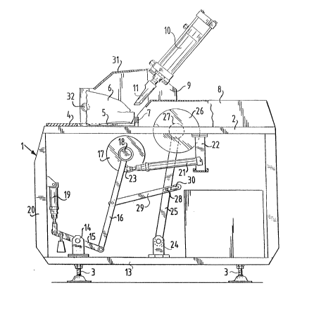
The device shown in fig. 1 is formed by a casing 1 which is
closed on its top by a plate 2 and which rests on the ground on
its bottom by means of adjustable legs 3. In preference the
casing is manufactured from stainless steel to enable easy
cleaning.
Arranged on top plate 2 is a support plate 4 extending
partially thereabove which is provided with a recess 5 for
positioning of the pig's head 6 for preparing. Forward of the
position where the pig's head comes to rest is arranged a set of
switches 7 which detect whether a pig's head is present. Above
the other part of upper plate 2 is a cover 8.
Fixed to the cover 8 is a support 9 to which a pneumatic
cylinder 10 is attached. A cutting member in the form of a
cleaving knife 11 is fixed to the piston rod of the pneumatic
cylinder.
In the middle of support plate 4 a continuous slot 12 is
arranged, as shown in fig. 2. The slot 12 otherwise also extends
through the greater part of upper plate 2 and through the front
wall of cover 8.
Arranged in the interior of the casing 1 against the bottom
13 of casing 1 is a support 14 to which a second lever 15 is
fixed rotatably. Fastened rotatably to one end of the second
lever 15 is a first lever 16, to the other end of which is fixed
a round knife 17 drivable in rotation. The knife-blade 17 is
drivable by means of a hydromotor 18 fixed on the first lever 16.
In addition the other side of the second lever 15 is connected to
the piston rod of a pneumatic cylinder 19 which is attached with
its fixed end to the front wall 20 of casing 1. When the
pneumatic cylinder 19 is energized the rotatably drivable knife-
blade 17 will thus be moved upward, wherein the knife-blade
extends through the slot 12.
For movement in substantially horizontal direction is
arranged a pneumatic cylinder 21 which is rotatably connected
with its fixed end to a support 22 fixed to the upper plate 2.
The piston rod 23 of this pneumatic cylinder 21 is connected to
the first lever 16. When the pneumatic: cylinder 21 is energized
the rotatable knife-blade 17 is moved in substantially horizontal
direction.
Finally, against the bottom 13 is arranged another support
24 to which a third lever 25 is rotatably fastened. Fixed to the
free end of the third lever 25 is a rotatably drivable saw-blade
26. The rotatably drivable saw-blade 26 is drivable by a
hydromotor 27.
The third lever 25 is provided with a pin 28 which extends
through a slot 30 arranged in a fourth lever 29. The third lever
25 will thus follow the movements of lever 16, albeit with a free
stroke which is caused by the length of slot 30. As a result the
rotatably drivable saw-blade 26 will follow with the same free
stroke in horizontal direction the movements in horizontal
direction of the rotatably drivable knife-blade 17.
Arranged above support plate 4 and in particular above the
recess 5 is a protective cage 31 which ensures that, when a head
for processing is present, the user cannot move with his hands
into the vicinity of the cleaving knife 11, knife-blade 17 or
saw-blade 27. As extra safety precaution safety switches 32 are
arranged on the sides of cage 31, wherein the driving and the
movement of said sawing, cleaving and cutting implements is only
possible when these switches 32 are pressed in. The distance
between both switches 32 is such that they cannot be pressed in
with one hand, so that the user needs both hands to press in the
switches and cannot therefore move his hands into the vicinity of
the dangerous components.
The operation of the device according to the invention will
now be elucidated. Firstly, a pig's head 6 is placed on the upper
plate 2, this as far as possible into the cavity 5, as shown in
fig. 3. The snout 33 of the pig's head herein rests against the
detection switches 7 so that the presence of the pig's head 6 is
detected and so that it is possible after pressing in the safety
switches 32 to set the cutting, cleaving and sawing implements
into operation.
r!
!~ J
The pneumatic cylinder 19 is first energized so that the
lever 16 is moved wholly upward, wherein pressure is also
supplied to the hydromotor 18. As a result thereof the knife-
blade 17 will begin to rotate. The rotating knife-blade 17 will
herein cut into the pig's head 6. The depth of the cut depends on
the force with which cylinder 19 is energized. This force is
selected such that the cut extends into the rind but not, or only
to a small extent, into the nose bone. The pneumatic cylinder 21
will herein likewise be energized so that the rotating knife-
blade 17 will displace in horizontal direction, wherein thepressure exerted by the pneumatic cylinder 19 is such that the
contour of the nose bone 39 is followed and that only the rind 38
is cut through. This operation is important for removing the mask
during the following butchering procedure.
During the horizontal movement of knife-blade 17 this
movement, after a certain dead zone dependent on the length of
slot 30, is transmitted by means of levers 16,29,25 to the
rotating saw-blade 26. This is of course driven in rotation by
the hydromotor 27. The rotating saw-blade herein makes a saw cut
through both the rostral bone 34 and the jaw-bone 35. The snout
of the pig's head is hereby sawn into two pieces, which
facilitates gripping by gripper members during the subsequent
butchering operation for removal of the mask. Furthermore, by
sawing the rostral bone 34 and the jaw-bone 35 each into two
pieces placing of the pig's head onto the pins is likewise
facilitated.
Air is then fed to the pneumatic cylinder 10 so that the
cleaving knife 11 moves downward and cuts through the snout 33 of
the pig, doing this between the rostral bone 34 and jaw-bone 35.
The cartilage 36 present therebetween is herein cut through. As a
result the rostral bone 34 comes loose so that in principle it is
possible to place the thus treated pig's head 6 on pins which
extend into the nasal cavity 37.
Reference is made in the above embodiment to pneumatically
driven cylinders. It will be apparent that these can be replaced
by hydraulically driven cylinders or by other linear drive
members. It should be noted here that it is less attractive to
replace the pneumatic cylinder 10 with a hydraulic cylinder
because for a good cleaving action it is important that the
inclined movement takes place as rapidly as possible; because of
the small mass of the air it is apparent that a pneumatically
driven cylinder has the advantage here.
For the driving use is made of hydromotors. This is of
course an attractive solution because a hydromotor has a small
volume and can thus be incorporated easily at the relevant
locations. It will be apparent that other types of drive means,
such as electric motors, can also be employed.
It can be attractive to increase the force on the knife
driven in rotation with a weight fixed to the second lever 25.
It will likewise be apparent that diverse other modifi-
cations can be made to the device.
The above stated sequence is performed to prevent the nose
from turning over. It is however possible within the scope of the
invention to use another sequence.