Note: Descriptions are shown in the official language in which they were submitted.
- ~9~813
EMBOSSING ROLLS
TECHNICAL FIELD
This invention relates to the art of embossing
and more particularly it relates to the formation of
embossing rolls. Even more specifically, the present
invention relates to a method for forming a seamless
embossing roll.
BACXGROUND OF THE ART
Numerous films are provided with decorative
indicia by an embossing process in which the film is
passed between a pressure roll and an embossing roll to
receive such decorative indicia. These films may be
formed of numerous polymeric materials including, for
e~ample, polyolefins, linear polyesters, polyamides and,
for e~ample, poly(vinyl chloride). Additionally these
films may optionally be provided with a suitable backing
such as, for e~ample, a reinforcing mesh backing of either
glass fibers or polymeric fibers such as poly(ethylene
terephthlate). The backing may be of the woven or the
non-woven type. The methods of manufacturing such films
are well known in the art. One specific field where such
embossed films are produced is in the manufacture of
wallcoverings.
There is a need in the art to provide a process
for manufacturing embossing rolls in a more economical
manner. There is also a need in the art for manufacturing
rolls which are capable of providing embossed, more
aesthetically pleasing ornamentation on films without the
- 209i~313
occurrence of seams. Additionally, in providing a process
for manufacturing embossing rolls, there is a need to
inject the skilled artist into the manufacturing process
to provide the decorative indicia for the rolls, and
thereby, provide the opportunity for the innovative
creation of a wide variety of ornamental patterns and
designs.
Presently, one technique for manufacturing
embossing rolls is an electroforming process in which a
segmented sleeve is formed. This segmented sleeve
provides for the occurrence of seams which is
aesthetically undesirable. This is also an espensive and
time consuming process and it removes the artist from the
process of forming the embossing cylinder.
US Patent No. 4,634,484 is directed to embossing
rollers and forms a sleeve which is positioned around a
core and used as the embossing medium. This sleeve is
made by a time consuming multi-step process which is
costly. In accordance with this process, a design on a
roller is coated with a silicone rubber to form an annular
member having indicia disposed internally. This sleeve is
then turned inside-out and used as an embossing medium to
emboss the esternal surface of a tube of thermoplastic
film. The tube of embossed thermoplastic film is then in
turn coated with a silicone rubber to form another annular
or cylindrical sleeve member which is then vulcanized and
turned inside-out. After being turned inside-out the
sleeve is drawn over a core roller, after the core roller
has been coated with an adhesion promoter and a silicone
adhesive, the adhesive coating is then hardened and the
composite roller is used as an embossing roller in a
2 ~ 1 3
device for the continuous embossing of a thermoplastic
rectilinear film. Obviously, this is a labor and capital
intensive process. Moreover, since the embossing roll is
a composite, as opposed to a unitary roll in which the
embossing indicia is integral and unitary with the
external surface of roll, there is a danger of slippage of
the sleeve along the underlying surface which can
seriously adversely impact production quality and
efficiency.
No molding of the decorating cylinder is
suggested by U.S. Patent 4634484.
US Patent No. 4,551,297 also discloses the
formation of a composite embossing or decorating cylinder
which includes a silicone sleeve member bearing indicia to
be embossed onto a film and wherein the sleeve is adhered
to the surface of a cylindrical core. This patent does
not describe the formation, by molding, of an embossing
cylinder within a sleeve.
Both of the above specific patents are
essentially directed at duplicating a leather grain and
are not concerned with providing a method wherein the
artists may e~ercise their innovative talents of creating
original patterns on a seamless cylinder for use in the
continuous embossing of films.
The present invention satisfies the above needs
in the art by providing for a process in which seamless
embossing rolls are formed in a highly economical manner
and in a short period of time. The embossing rolls formed
by this invention are unitary; that is, the embossing
2 ~ 3 1 ~ :1 3
indicia is integral with the surface of the rolls and is
not on a separate sleeve member requiring an additional
process step of adhesively adhering the sleeve member to a
supporting surface. Furthermore, the present process
integrates the artist into the embossing roll production
process. The artist can now provide a variety of artistic
and original decorative indicia into the rolls which, in
turn, will be embossed on the film.
DISCLOSURE OF THE INVENTION
The above needs are satisfied by providing a
method for forming a decorating cylinder, i.e. an
embossing roll, having indicia desired to be embossed onto
a film, the method, or process, comprises molding a
seamless curable cylinder within a seamless sleeve, said
sleeve having said indicia in reverse from about the inner
circumference thereof and said cylinder thereby being
provided with said indicia on its outer circumference.
The molded cylinder is then cured and used as the improved
seamless decorating cylinder to emboss films.
When reference is made herein to indicia and
reversed indicia, it will, of course, be apparent that
indicia can either be positive or impastoed indicia, i.e.
raised surfaces in the nature of a letter press or the
indicia can be characterized by recessed surfaces in the
nature of a gravure type printing surface. Reversal
simply means reversing the indicia from positive, that is
raised, to negative, that is recessed, or vice-versa.
Thus, any specific pattern, or indicia, can be viewed to
be the result of either providing recessed surfaces or
impastoed surfaces to define such pattern.
2~91813
In accordance with another feature of this
-
invention there is provided a method for producing a
seamless embossing roll comprising: forming a pattern on
the external surface of a modelable, hardenable seamless
sleeve member; hardening said sleeve member; turning said
sleeve inside-out; dispensing a moldable, hardenable
material into the inner portion of said turned inside-out
sleeve and allowing said material to mold against the
internal surface of said turned inside-out sleeve and
hardening said material to form a seamless cylindrical
member having a reversal of said pattern on the external
surface of said member.
In accordance with yet another feature of this
invention, a method is provided for forming a decorating
cylinder having indicia thereon which is desired to be
embossed onto a film, the method comprising: (i)
providing a smooth cylindrical member comprised of a
seamless sleeve having an outer e~posed surface of an
imprintable material; (ii) modeling, or forming, first
indicia into said outer surface of said imprintable
material; (iii) forming a continuous seamless sleeve about
said cylindrical member, said sleeve thereby having molded
on its internal surface first indicia in reversed form
(iv) molding a curable cylinder within and against the
inner surface of said sleeve, said cylinder having indicia
desired to be embossed onto a film which substantially
corresponds to the first indicia. Thereafter the molded
curable cylinder is cured and the resulting decorating
cylinder is used in a conventional manner to emboss
indicia onto a polymeric film. According to a further
aspect, the method comprises embossing a film with the
formed decorating cylinder to thereby produce a master of
289~1~13
the indicia and thereafter using said master to model
~ indicia into the outer surface of another smooth
cylindrical member comprised of a seamless sleeve having
an outer embossed surface of an imprintable material.
s
In accordance with a highly preferred embodiment
of this invention, the above need in the art is satisfied
by a method for forming a decorating cylinder having
indicia which is to be embossed onto a film, the method
comprising: imprinting at least a portion of the external
circumference of a seamless cylindrical sleeve member to
provide a recessed pattern; turning said cylindrical
sleeve member inside-out so as to have said recessed
pattern disposed on the internal portion of said sleeve;
molding an embossing cylinder having said recessed pattern
in reversed form within said sleeve, said molding being
done by dispensing a molding resin inside the turned
sleeve.
BRIEF DESCRIPTION OF THE DRAWINGS
Referring to the drawings:
Figure 1 schematically illustrates one step in the process
of the present invention;
Figure 2 schematically illustrates another step in which
indicia are modelled into a cylinder;
Figure 3 represents another step in the process showing
the formation of a sleeve;
Figure 4 represents another step in the process showing
the molding of an embossing roll within the formed sleeve;
Figure 5 schematically illustrates the use of an embossing
roll in accordance with this invention;
Figure 6 illustrates a step in an alternate and preferred
20~13
embodiment of this invention;
- Figure 7 represents a further step in a preferred
embodiment of this invention;
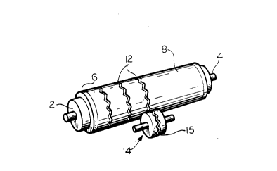
Figure 8 shows a decorating cylinder produced in
accordance with this invention.
DETAILED DESCRIPTION OF THE INVENTION INCLUDING THE
BEST MODE OF CARRYING IT OUT
The drawings illustrate various steps in the
present method for forming decorating cylinders, or
embossing rolls, having indicia which are to be embossed
onto a film. Any of a wide variety of films may be so
embossed, especially polymeric films like poly(vinyl
chloride) and the polyolefins. Importantly, the method
comprises molding a seamless decorating cylinder within a
seamless sleeve which sleeve carries a design along the
internal circumference thereof, and hence the reverse form
of the design is molded into the esternal surface of the
decorating cylinder. This decorating cylinder is then
used in a conventional manner as the embossing medium or
roll.
Referring now to Figures 1-4, a metal core
cylinder 2 carrying a central shaft 4 and opposed flanges
6 is first provided with a sleeve 8 of a hardenable and
imprintable material. This imprintable material is in the
nature of what is commonly referred to as modelling clay
but more accurately is a plastic molding compound. The
plastic molding material is formed into a sleeve, or
seamless cylinder, 8 within the flanges 6 around core 2
and, by means of a leveling roller 10, is smoothed into 3
uniform surface. An especially preferred imprintable
2 0 !3 1 ~ 1 3
material for this purpose is a plasticized poly(vinyl
chloride). One such material is the material available
from Polyform Products Company as their Super Sculpey
product line.
The next step in the process, as seen in Figure
2, is to form or, model indicia in the outer surface of
the imprintable cylindrical member 8. In Figure 2,
indicia, or pattern, 12 is schematically shown to be
formed into the imprintable sleeve 8 using a device 14
which is in the form of a roller carrying raised indicia
15. Depending on the nature of the pattern to be formed
in the sleeve 8 of modelling material, the indicia 12 may
either be recessed or it may be raised, or impastoed.
Preferably, the plastic modelling material with the
pattern formed in its circumferential e~ternally disposed
surface is then heat-hardened. These modelling compounds
are preferably of a plasticized poly(vinyl chloride) and
have heat-hardening cycles of about 250 to 325 F for
about 5 to about 15 minutes.
After the heat-hardening of the hardenable
plastic modelling material, a continuous elastic seamless
sleeve 16 is formed about the cylindrical sleeve 8 in such
a manner that the newly formed sleeve is provided on its
internal surface with a reversed form of the indicia 12,
initially formed as set forth in Figure 2. These steps
are generally best appreciated by reference to Figure 3.
Opposed flanges 14 are applied over core 2 outwardly of
flanges 6. They have diameters larger than the diameter
of the hardened modelling compound of sleeve 8. Within
the confines of flanges 14 and around the cylindrical
surface of the hardened sleeve 8, an annular or sleeve
2091.~13
member 16 is then formed generally in the same manner as
~ was seamless cylinder 8.
Seamless sleeve 16 is of a moldable material
which likewise can be hardened such as, for example, by
heat. This material is resilient and flexible after
heating. Silicone rubbers generally are most suitable for
this purpose. One such material is Thixotropic POR-A-MOLD
prepolymer and S-333TA curative commercially available
from the Synair Corp. The materials are used in a ratio
of 1:1 (by volume). The mi~ture hardens and curls at room
temperature in 12 to 24 hours.
In order to maintain rigidity and stability for
molding and during heating of sleeve 16, an outer
circumscribing and reinforcing mold 18 such as, for
example, plaster of Paris is formed around seamless
cylinder sleeve 8. Because of the moldable nature of the
material of seamless sleeve 16, the internal surface molds
and conforms to the indicia 12. Thus, the indicia formed
on the internal surface of sleeve 16 is the reverse form
of the indicia in the hardened modelling material of
sleeve 8. In Figure 4, this reversed indicia is shown as
inwardly e~tending protuberances 20.
After solidifying and hardening the material of
sleeve 16, for example by curing at room temperature the
elastic sleeve 16 is separated from the assembly
illustrated in Figure 3. It is then used to mold the
decorating cylinder as generally illustrated in Figure 4.
Referring now to Figure 4, it will be seen that
seamless sleeve 16 is sealingly supported on opposed step
~ 0 ~ 3
flanges 22 and, again for rigidity and support, disposed
~ about sleeve 16 is a reinforcing and supporting mold
structure 24, formed of plaster of Paris. Core rod 26
extends between and through step flanges 22 and includes
outer rods 28 which can be used to secure the final
embossing roll in a conventional embossing mechanism.
Upper step flange 22 has an opening 30 through which the
moldable and hardenable material used to form decorating
cylinder or embossing roll 32 is added inside sleeve 16.
Especially suitable materials for the final embossing roll
32 are cured polyurethanes and cured epo2ies with an
especially preferred formulation being EPON 828 epoxy 100
parts manufactured by Shell along with an amine curative
(100 parts) sold under the designation Ancamide 260A by
Pacific Anchor Chemical Corporation. After the material
used to form decoration cylinder 32 is added within the
internal confines of sleeve 16 and sufficient time is
allowed for the material to mold against the internal
surface of sleeve 16, the material is cured. This can be
done by heating, for example, at a temperature of 140F
for two hours and then at 212F for one hour. The curing
also binds the material to core rod 26. Esternal
supporting structure 24 and fle2ible sleeve 16 are then
separated from the cured embossing cylinder 32.
Figure 5 generally shows the use of embossing
roll 32 to provide the embossing indicia 12' onto a
polymeric film 36. The embossing is done by passing film
36 through the nip provided by embossing roll 32 and a
compression roll 38.
Figure 5 also schematically illustrates another
embodiment of the invention wherein at least a portion of
--10--
2~9 i813
the film 36 is later employed as a master. In this
~`~ embodiment, film 36 with indicia 12' is used later to
provide the indicia 12 onto the imprintable material of
sleeve 8 as set forth in Figure 2. In other words, the
material 36 with the indicia 12' is used as a substitute
for the device 14 schematically illustrated in Figure 2.
As will be apparent from the foregoing, one of
the advantages of the present invention is that in
providing the indicia 12 into the moldable material, as
set forth in Figure 2, an artist is now free to create any
ornamental and original pattern as such artist desires.
This can be done by the use of a any positive device, or
jig, to form recessed indicia of the desired pattern in
the surface of sleeve 8 .
Figures 6-8 along with Figures 2 & 4 generally
schematically illustrate an alternate, and preferred,
embodiment of this invention. In accordance with this
embodiment, the molding step generally set forth in Figure
3 is eliminated.
In this embodiment, a pattern is first formed on
the external portion of the moldable, hardenable, seamless
sleeve member as set forth in Figure 2. The sleeve is
then hardened as previously described but the material
used in this embodiment needs to be more fle~ible and
resilient than the material which can be used in the
previous embodiment. After hardeninq, the sleeve is then
turned inside-out and the inside-out sleeve is then used
as a mold member into which a moldable, hardenable
material which is to be used to form the embossing roll is
dispensed and allowed to flow and mold against the inner
2~.9 1 ~3
- portion of the sleeve. This molded material is then
hardened to produce the embossing roll, namely a seamless
cylindrical member having a pattern which is the reverse
of the pattern initially formed in the external portion o~
the moldable, hardenable seamless sleeve member before i~s
hardening and being turned inside-out.
More specifically, in this embodiment, the
moldable material is formed as a smooth, seamless sleeve 8
about core 2 in the manner described above with regard to
Figures 1 & 2. Here, however, as indicated a material is
needed which is flexible and resilient after hardening.
One preferred material for this embodiment of the
invention is a plastic molding material sold under the
lS designation Super Elasticlay by the Polyform Products Co.
The ne~t step is to form a pattern in sleeve 8 as by
imprinting indicia 12 into at least a portion of the
e~ternal circumference of the seamless cylindrical sleeve
member 8 to provide indicia, in this e~ample, in the form
of a recessed pattern. The indicia-bearing, moldable
material in the form of the endless, seamless sleeve 8 is
then hardened by heating at about 300F for 15 to 30
minutes. As seen in Figure 6, sleeve 8 of the now
hardened resilient material bearing recessed indicia 12 is
turned inside-out so that the indicia 12 is now disposed
on the internal portion of the sleeve. The turned
inside-out sleeve is designated 40 in Figure 7.
The final embossing roll is formed in the manner
e~plained above with regard to Figure 4 and as generally
illustrated in Figure 7. The curable moldable epo~y resin
is placed within sleeve 40 outwardly of a core cylinder 25
and e~tending rods 28. As in the case with the previous
-12-
8 ~ 3
embodiment, an outer supporting mold 24 is also provided.
- The epoxy is allowed to flow into the recesses of indicia
12 to form outwardly extending protuberances 44 on the
embossing roll 42. Thereafter the roll is cured as above
and the roll used in the manner of Figure 5 to emboss film
36.
Thus, having described the present invention, it
of course will be apparent that modifications are possible
which pursuant to the patent statutes and laws, including
application of the doctrine of equivalents, do not depart
from the spirit and scope of this invention.