Note: Descriptions are shown in the official language in which they were submitted.
TITLE
CROSS GROOVE CONSTANT VELOCITY JOINT CAGE
HAVING ANGLED BALL RETAINING WINDOWS
BACKGROUND OF THE INVENTION
This invention relates in general to universal joints
and in particular to an improved structure for a
constant
velocity type of universal joint.
A universal joint is a mechanical coupling device
which provides a rotational driving connection between
two
rotatable shafts, while permitting such shafts to
be
oriented at an angle relative to one another. Universal
joints are commonly used in the drive train systems
of
vehicles. For example, a universal joint is commonly
used
to provide a rotational driving connection between
a drive
shaft rotatably driven by a vehicle engine and an
input
shaft connected to the vehicle axle assembly. This
is
because the drive shaft and the axle assembly input
shaft
are rarely co-axially aligned. To accommodate this
non-alignment, while still providing a rotational
driving
connection, a universal joint is utilized therebetween.
Universal joints are commonly classified by their
operating characteristics. One important operating
characteristic relates to the relative angular velocities
of the two shafts connected thereby. In a constant
velocity type of universal joint, the instantaneous
angular
velocities of the two shafts are always equal, regardless
of the angular orientation of the shafts. In a
non-constant velocity type of universal joint, the
instantaneous angular velocities of the two shafts
vary
with the angular orientation of the shafts (although
the
average angular velocities for a complete revolution
are
equal).
1
~~~~~~2
A typical constant velocity universal joint includes a
cylindrical inner race connected to one of the shafts and a
hollow cylindrical outer race connected to the other of the
shafts. The outer surface of the inner race and the
inner
surface of the outer race have respective pluralities
of
grooves formed therein. The grooves extend linearly,
having generally semi-circular cross sectional shapes.
Each groove formed in the outer surface of the inner
race
is associated with a corresponding groove formed
in the
inner surface of the outer race. A ball is disposed
in
each of the associated pairs of grooves. The balls
provide
a driving connection between the inner and outer
races. A
generally hollow cylindrical cage is typically provided
between the inner and outer races for retaining the
balls
i5 in the grooves. The cage has circumferentially extending
inner and outer surfaces and a plurality of openings
formed
therethrough for receiving and retaining the balls.
;,.,, In one known type of constant velocity joint, the
grooves formed in the outer surface of the inner
race are
20 oriented so as to be alternately inclined relative
to the
rotational axis of the joint. Similarly, the grooves
formed in the inner surface of the outer race are
also
alternately inclined relative to the rotational axis
of the
joint. For each pair of associated inner and outer
race
25 grooves, the inner race groove is inclined in one
direction
relative to the rotational axis of the joint, while
the
outer race groove is inclined in the opposite direction.
Thus, this type of joint is commonly referred to
as a cross
groove constant velocity joint or, more simply, a
cross
30 groove joint.
Most cross groove joints permit the inner race and its
associated shaft to move axially relative to the outer race
and its associated shaft. Thus, the center point of the
inner race (i.e., the point defined by the intersection of
35 the axis of rotation of the inner race with a perpendicular
2
plane bisecting the inner race) can be axially displaced
from center point of the outer race. This axial
displacement is desirable because it permits the two shafts
to move axially relative to one another during operation.
However, it has been found that the ability of the
cross groove joint to accommodate angular movement between
the two shafts is inversely related to the ability of the
joint to accommodate axial movement therebetween. In other
words, as the center points of the two races are displaced
t0 at a greater distance, the joint can accommodate a lesser
amount of relative angular movement therebetween. For
example, a typical joint may accommodate an angular
orientation of 18.0° between the two shafts when the center
points of the inner and outer races are displaced by
i5 14.7mm. The same joint will accommodate only an angular
orientation of 6.0° when such center points are displaced
by 24.Omm.
This inverse relationship between the angular movement
and axial displacement of the inner and outer races is a
20 result of the internal structure of the cross groove joint.
Specifically, it has been found that when the center point
of the inner race is axially displaced from the center
point of the outer race, angular movement of the inner race
causes the center point thereof to move laterally with
25 respect to the center point of the outer race. As a
result, the center point of the inner race moves out of
alignment with the axis of rotation of the outer race.
Consequently, angular movement of the inner race causes the
outer surface thereof to engage the inner surface of the
3o cage, preventing further angular movement. The ratio of
this lateral movement of the center point of the inner race
to the amount of angular movement increases with the amount
of axial displacement of the center points of the inner and
outer races. Thus, as the center points of the inner and
35 outer races are displaced at a greater distance, the joint
3
can accommodate a lesser amount of relative angular
movement therebetween.
It is known to design cross groove joints to meet the
specific angular movement and axial displacement
requirements of a particular application. This is usually
accomplished by enlarging the entire joint structure to
accommodate both greater angular movements and axial
displacements than would otherwise be available. However,
it would be desirable to provide an improved structure for
a cross groove joint which can accommodate both greater
angular movements and axial displacements than previously
attainable without increasing the overall size thereof.
SUMMARY OF THE INVENTION
This invention relates to an improved structure for a
cross groove constant velocity universal joint which can
accommodate both greater angular movements and axial
displacements than previously attainable with comparably
sized cross groove joints. The joint includes an inner
race having a plurality of outer grooves, an outer race
having a plurality of inner grooves, and a ball disposed in
each of the associated pairs of grooves. For each pair of
race grooves, the inner race groove is inclined in one
direction relative to the rotational axis of the joint,
while the outer race groove is inclined in the opposite
direction. A hollow cylindrical cage is provided between
the inner and outer races. The cage has openings formed
therethrough which receive the balls therein to retain them
in the grooves. The diameter of the inner surface of the
cage is enlarged to accommodate lateral movement of the
center point of the inner race when it is moved both
axially and angularly relative to the outer race. The ball
retaining openings are formed having side walls which are
angled relative to a plane bisecting the cage. The side
walls taper toward one another from the inner surface of
4
2~~~~~~
the cage to the outer surface thereof. The angled side
walls position the points of contact of the balls a
sufficient distance away from the edges of the openings to
prevent damage during operation. In addition, the angled
side walls engage the balls to prevent the cage from
chattering during operation.
Various objects and advantages of this invention will
become apparent to those skilled in the art from the
following detailed description of the preferred
embodiments, when read in light of the accompanying
drawings.
BRIEF DESCRIPTION OF THE DRAWINGS
Fig. 1 is an exploded perspective view of a prior art
constant velocity universal joint.
Fig. 2 is a sectional elevational view of the prior
art constant velocity joint of Fig. 1 shown assembled.
Fig. 3 is an enlarged sectional elevational view of a
portion of the prior art constant velocity joint of Fig. 2.
Fig. 4 is a view similar to Fig. 3 showing a first
embodiment of an improved constant velocity joint in
accordance with this invention.
Fig. 5 is a view similar to Fig. 4 showing a second
embodiment of an improved constant velocity joint in
accordance with this invention.
DETAILED DESCRIPTION OF THE PREFERRED EMBODIMENT
Referring now to the drawings, there is illustrated in
Figs. 1, 2, and 3 a prior art cross groove constant
velocity universal joint, indicated generally at 10, in
accordance with this invention. The prior art joint 10
includes an inner race 11 which is generally hollow and
cylindrical in shape, defining an axis of rotation
therethrough. The inner race 11 has a central splined
opening 12 formed therethrough. The splined opening 12 is
5
adapted to receive a splined end of a first shaft (not
shown) for rotation therewith in a known manner.
The inner race 11 has an outer surface 13 which is
generally cylindrical in shape, but which is slightly
curved along the axis of rotation (as best shown in Fig.
2). A plurality of grooves 14 are formed in the outer
surface 13 of the inner race 11. In the illustrated
embodiment, six of such grooves 14 are formed in the outer
surface 13, although a greater or lesser number may be
provided. The grooves 14 extend linearly, each having a
generally semi-elliptic or gothic cross sectional shapes.
The grooves 14 are alternately inclined relative to the
rotational axis of the inner race 11.
The prior art joint 10 further includes an outer race
15 which is also generally hollow and cylindrical in shape,
defining an axis of rotation therethrough. The outer race
15 is adapted to be connected to a second shaft (not shown)
for rotation therewith in a known manner. The outer race
15 has an inner surface 16 which is generally cylindrical
in shape. A plurality of grooves 17 are formed in the
inner surface 16 of the outer race 15. The number of such
grooves 17 is the same as the number of grooves 14 formed
in the outer surface 13 of the inner race 11.
As with the inner race grooves 14, the outer race
grooves 17 extend linearly and have generally semi-elliptic
or gothic cross sectional shapes. The grooves 17 are
alternately inclined relative to the rotational axis of the
outer race 15. Each of the outer race grooves 17 is
associated with a corresponding one of the inner race
grooves 14. For each of the pairs of inner and outer race
grooves 14 and 17, the inner race groove 14 is inclined in
one direction relative to the rotational axis of the joint,
while its associated outer race groove 17 is inclined in
the opposite direction.
6
A generally hollow cylindrical cage 20 is disposed
between the outer surface 13 of the inner race 11 and the
inner surface 16 of the outer race 15. The cage 20 is
formed having an inner surface 21 which is generally
cylindrical in shape and an outer surface 22 which is
generally spherical in shape. A plurality of openings,
each indicated generally at 23, is formed about the
circumference of the cage 20. Each of the openings 23
extends radially from the inner surface 21 to the outer
surface 22. A ball 24 is disposed within each of the
openings 23. As best shown in Fig. 2, each ball 24 extends
partially into each of the associated alternately inclined
grooves 14 and 17 formed in the inner and outer races 11
and 15, respectively. As a result, a driving connection is
provided between the inner and outer races 11 and 15, while
relative angular movement and axial displacement is
permitted therebetween.
Referring now to Fig. 3, the structure of the cage 20
of the prior art joint 10 is illustrated in detail. As
shown therein, each of the openings 23 formed through the
cage 20 is defined, in part, by a pair of opposed side
walls 25. The side walls 25 extend from respective inner
corner edges 26 (defined at the intersections of the side
walls 25 with the inner surface 21) to respective outer
corner edges 27 (defined at the intersections of the side
walls 25 with the outer surface 22). The side walls 25 are
oriented parallel relative to a perpendicular plane
bisecting the cage 20. Thus, the distance separating the
inner corner edges 26 is equal to the distance separating
the outer corner edges 27.
As previously mentioned, a ball 24 is disposed within
each of the openings 23. As shown in Fig. 3, the ball 24
engages each of the side walls 25 at a point of contact 28.
The cage 20 is designed such that the points of contact 28
are located a predetermined distance away from the inner
7
~;~:~ l~~j~
corner edges 26. This is done to prevent such inner
corner
edges 26 from becoming chipped or otherwise damaged
during
operation of the joint 10. In the embodiment illustrated
in Fig. 3, R1 represents a radius which extends from
the
rotational axis of the joint 10 to the inner corner
edges
26, and X1 represents the distance between the inner
corner
edges 26 and the points of contact 28. In a typical
prior
art joint 10, the radial distance Rl can be approximately
1.270 inches, while the radial distance X1 can be
approximately 0.040 inch.
As discussed above, the ability of the prior art joint
to accommodate angular movement between the inner
race
11 and the outer race 15 is inversely related to the
ability of the joint l0 to accommodate axial movement
therebetween. This occurs because the center point
of the
inner race 11 moves laterally with respect to the
center
point of the outer race 15 when the inner race 11
is
axially and angularly displaced from the outer race
15.
Consequently, the outer surface 13 of the inner race
11
engages the inner surface 21 of the cage 20, preventing
further angular movement. Thus, it would be desirable
to
provide an improved structure for a constant velocity
joint
10 which permits increased the axial and angular movements,
while not increasing the overall size thereof.
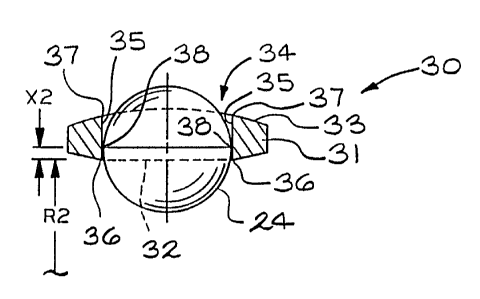
Referring now to Fig. 4, there is illustrated a
portion of a first embodiment of an improved constant
velocity joint, indicated generally at 30, in accordance
with this invention. The joint 30 is similar to the
prior
art joint 10 described above, except that the prior
art
cage 20 has been replaced by an improved cage, indicated
generally at 31. The cage 31 is formed having an inner
surface 32 which is generally cylindrical in shape
and an
outer surface 33 which is generally spherical in shape.
A
plurality of openings, each indicated generally at
34, is
formed about the circumference of the cage 31. Each
of the
8
~~9~~~~
openings 34 extends radially from the inner surface
32 to
the outer surface 33. A ball 24 is disposed within
each of
the openings 34.
Each of the openings 34 formed through the cage 31
is
defined, in part, by a pair of opposed side walls
35. The
side walls 35 extend from respective corner edges
36
(defined at the intersections of the side walls 35
with the
inner surface 32) to respective corner edges 37 (defined
at
the intersections of the side walls 35 with the outer
surface 33). As with the prior art cage 20, the side
walls
35 of the cage 31 are oriented parallel relative
to a
perpendicular plane bisecting the cage 31. Thus,
the
distance separating the inner corner edges 36 is
equal to
the distance separating the outer corner edges 37.
As shown in Fig. 4, the ball 24 engages each of the
side walls 35 at a point of contact 38. In the embodiment
illustrated in Fig. 4, R2 represents a radius which
extends
from the rotational axis of the joint 30 to the inner
corner edges 36, and X2 represents the distance between
the
inner corner edges 36 and the points of contact 38.
To
accommodate the increased axial and angular movement,
the
radial distance R2 of the improved joint 30 is greater
than
the radial distance R1 of the prior art joint 10.
For
example, the radial R2 can be approximately 1.290
inches.
As a result, the inner race of the improved joint
is
permitted an additional lateral movement of approximately
0.040 inch, resulting in a significant increase in
the
axial and angular capability of the joint 30.
If the radial distance R2 is increased by 0.020 inch,
30 the radial distance X2 will be reduced by a similar
amount.
Thus, the radial distance X2 separating the inner
corner
edges 36 from the points of contact 38 will be reduced
to
approximately 0.020 inch. While this may function
adequately in some situations, it has been found
that this
is not a sufficient distance to prevent the balls
24 from
9
chipping or otherwise damaging the inner corner edges
36
during operation of the joint 30. Thus, it would be
desirable to provide a further improved structure
for the
joint 30 which not only permits increased the axial
and
angular movements, but also prevent the inner corner
edges
from becoming damaged.
Referring now to Fig. 5, there is illustrated a
portion of a second embodiment of an improved constant
velocity joint, indicated generally at 40, in accordance
t0 with this invention. The joint 40 is similar to the
joint
30 described above, except that the cage 31 has been
replaced by a further improved cage, indicated generally
at
41. The cage 41 is formed having an inner surface
42 which
is generally cylindrical in shape and an outer surface
43
which is generally spherical in shape. A plurality
of
openings, each indicated generally at 44, is formed
about
the circumference of the cage 41. Each of the openings
44
H,3 extends radially from the inner surface 42 to the
outer
surface 43. A ball 24 is disposed within each of the
openings 44.
Each of the openings 44 formed through the cage 41
is
defined, in part, by a pair of opposed side walls
45. The
side walls 45 extend from respective corner edges
46
(defined at the intersections of the side walls 45
with the
inner surface 42) to respective corner edges 47 (defined
at
the intersections of the side walls 45 with the outer
surface 43). Unlike the prior art cage 20 or the cage
31,
the side walls 45 of the cage 41 are not oriented
parallel
relative to a perpendicular plane bisecting the cage
41.
Rather, such side walls 45 are oriented at an angle
relative to a perpendicular plane bisecting the cage
41.
Thus, the distance separating the inner corner edges
46 is
greater than the distance separating the outer corner
edges
47. For example, the side walls 45 may be oriented
at an
10
i~ ," .
angle of approximately 7° relative to a perpendicular plane
bisecting the cage 41.
As shown in Fig. 5, the ball 24 engages each of the
side walls 45 at a point of contact 48. In the embodiment
illustrated in Fig. 5, R3 represents a radius which extends
from the rotational axis of the joint 40 to the inner
corner edges 46, and X3 represents the distance between the
inner corner edges 46 and the points of contact 48. The
radial distance R3 of the further improved joint 40 is
equal to the radial distance R2 of the improved joint 30.
Thus, the joint 40 permits the same increased axial and
angular capabilities as the joint 30.
However, the distance X3 is significantly greater than
the radial distance X2. For example, depending upon the
~5 magnitude of the angular orientation of the side walls 35,
the distance X3 may be approximately 0.040 inch or greater.
This increased distance of separation between the inner
;,2; corner edges 46 and the points of contact 48 insures that
the balls 24 will not damage such inner corner edges 46
20 during operation of the joint 40.
The important features of this embodiment of the
invention, therefore, are that angled side walls 45 of the
cage 41 permit the radius of the inner surface 42 of the
cage 41 to be increased, thus permitting increased axial
25 and angular capabilities in the joint 40. At the same
time, the angled side walls 45 are effective to locate the
points of contact 48 a sufficient distance away from the
inner corner edges 46 to prevent the inner corner edges 46
from becoming damaged during operation of the joint 40.
30 Additionally, it has been found that as the operating angle
of the joint 40 varies and the balls 24 are continuously
re-positioned within the cage 41 by the inner and outer
races, the angled side walls 45 tend to pinch the balls 24,
preventing the cage 41 from moving. As a result,
35 chattering of the cage 41 during operation is prevented.
11
In accordance with the provisions of the patent
statutes, the principle and mode of operation of this
invention have been described and illustrated in its
preferred embodiments. However, it must be understood that
the invention may be practiced otherwise than as
specifically explained and illustrated without departing
from its spirit or scope.
20
30
12