Note: Descriptions are shown in the official language in which they were submitted.
p~TiSE
Applicant: Lars HILLHOHM
1~ motorized w2aes~barrow
FIELD OF THE INVENTION AND PRIOR ART
The present invention relates to a motorized wheelbarrow with a
pan for receiving a load to be transported by the barrow, at
least one wheel arranged to bear on the ground and a motor
arranged to rotate the wheel for moving the wheelbarrow over
the ground, said motor being arranged under the pan.
Motorized wheelbarrows of this type are already known and are
used primarily on rough ground, such as in mountain regions,
where a tractor or similar vehicle has difficulties to ° or
impossibly may - move ahead and different types of building
work has to be carried out. However, ruotorized wheelbarrows may
toe used for transporting goods in all conceivable situations,
in which the person handling the wheelbarrow for any reason,
such as for example lack of physical strength, wishes to have
motor assistance for moving the wheelbarrow.
Motorized wheelbarrows are already known by for instance SE
published patent application 7~D4333-7 as well as the pamphlet
concerning "motorskottkarra°' published by the company Fogelsta
Industri AB. In these two motor driven wheelbarrows already
known the motor is arranged at a substantial distance behind
the respective wheel axle as seen in the direction of movement
of the wheelbarrow, which considerably restricts the possi°
bilities to design the rest of the wheelbarrow. The weight of
the motor and the torque exerted thereof with respect to the
wheel axle makes it necessary to provide the wheelbarrow in
z
question with some kind of support wheels which bear on the
ground in the region of the motor. This permanent necessity of
support wheels may be a considerable disadvantage on rough
ground, on which it in the practice probably will be so that
the driver of the wheelbarrow has to carry a great portion of
the weight otherwise resting on the support wheels himself.
The moment or torque of the motor with respect to the wheel
axle also makes it heavy to empty the wheelbarrow forwardly by
pivoting the pan of the barrel about an axis being substan-
tially parallel to the wheel axle. In addition, the motor is in
the way of the body of the person carrying out the tilting,
which makes this uncomfortable, not at least considering the
exhaust gases created in an internal combustion engine or the
risks for burns, oil stains and so on.
It is important that the wheel of the wheelbarrow has a suffi-
cient size so that the wheelbarrow may be moved in a stable way
without friction losses being too great. In order to avoid
risks for tilting laterally it is at the same time important
that the centre of gravity of the load resting in the pan is
located as low as possible. These two goals as well as the wish
to be able to house a load volume being as great as possible in
the pan are contradictory to each other. As a consequence of
the location of the motor in the motorized wheelbarrows already
known the wheel has to be placed further to the rear end as
seen in the direction of movement as would be the case without
a motor. This leads to that the wheel is placed in the middle
under the pan itself, which makes it necessary to restrict the
height and thereby the volume of the pan for preventing the
centre of gravity of the loaded pan from coming so height above
the ground that the wheelbarrow gets difficult to handle. It
would of course be possible to place the wheel further to the
front, but this would lead to that the weight on the rear
support wheels will be too heavy and these would tend to
penetrate into the ground and slow down the movement of the
barrow. It should also be mentioned that it in motorized
3
wheebarrows is often desirable to utilize the ability of the
motor to drive forwardly to carry a bigger amount of load per
transport than would have been possible with a wheelbarrow
moved by man power.
BRIEF DESCRIPTION OF THE INVENTION
The present invention i:~ directed toward the provision. of a
motorized wheelbarrow finding remedy to the inconveniencies
mentioned above of the mcatorized wheelbarrows already known.
In accordance with one aspect of the present. invention, there
is provided a motorized wheelbarrow for transporting a load,
comprising a frame having forward and rearward ends; a pan for
receiving the load to be transported, the pan having forward
and rearward ends; at least one wheel mounted on the frame and
arranged to bear on the ground; a motor mounted on the frame
and arranged under the pan to rotate said wheel and move the
wheelbarrow over the ground; the frame with both said motor
and the wheel mounted thereon constituting a frame assembly
and the frame assembly being releasably secured to the pan so
as to be separable from the pan as a single integral unit; at
least one longitudinal member having a handle thereon and
being mounted to one of the pan and the frame assembly, the
longitudinal member beir~.g separable from the frame assembly;
the pan having a wall inclining forwardly-upwardly towards a
front edge thereof for emptying the load upon tilting the
wheelbarrow forwardly about an axis being substantially
parallel to said wheel axle, the wheel and the motor being
arranged under the wall. with the motor along said wall and in
front of and above the wheel axlE~ when the wheel is rolled
across the ground; the wall having an underside and the frame
being releasably attachable to the underside of the wall of
the pan; said frame having an
CA 02095031 2001-10-15
CI
elongated member at one c~f the ends and arranged to enter into
engagement with a stop member on the pan for stopping
forwardly-upwardly displacement of the frame along the wall,
the elongated member extending alongside the underside
substantially parallel to the wheel axle and adjacent to one
of the ends of the pan when the elongated member is engaged
with the stop member on the pan, and the end of the frame
opposite the elongated member ~~5 being arranged to be
releasably secured by securing means on the underside of the
wall of the pan while the elongated member is in engagement
with the stop member, and the stop member being arranged to
retain the elongated member in engagement therewith when the
end of the frame opposite the elongated member is secured to
the pan by the securing means.
In the invention, therefore, the motor of a wheelbarrow
defined in the introduction is located with centre of gravity
in front of a vertical plane including the axle of rotation of
the wheel as seen in the direction of movement in the
transport position of thEe wheelbarrow.
In accordance with a further aspect of the present invention,
there is provided a motorized whee=Lbarrow for transporting a
load, comprising a frame having forward and rearward ends; a
pan for receiving the load to be transported, the pan having
forward and rearward ends; at least. one wheel mounted on the
frame and arranged to b~a.~r on the ground; a motor mouni~ed on
the frame and arranged under the pan to rotate the wheel and
move the wheelbarrow over the ground; the frame with both the
motor and the wheel mounted thereon constituting a frame
assembly and the frame assembly being releasably secured to
the pan so as to be reparable from the pan as a single
integral unit; the wheel- having an axle defining an axis of
rotation and the motor having a center of gravity located in
CA 02095031 2001-10-15
3b
front of a vertical plane :including the axis of rotation of
the wheel; at least one longitudinal member having a handle
thereon and being mounted to one of the pan and the frame
assembly, the longitudinal member being separable from the
frame assembly; the par._ having a wall inclining forwardly-
upwardly towards a fronl~ edge thereof for emptying the load
upon tilting the whee:L~~arrow forwardly about an axis being
substantially parallel to the whee=L axle, the wheel and the
motor being arranged under t:he wall. with the motor along the
wall and in front of and above the wheel axle when the wheel
is rolled across the ground; the wall having an underside and
the frame being releasably attachab:Le to the underside of the
wall of the pan; the frame having an elongated member at one
of the ends and arranged to enter into engagement with a stop
member on the pan for stopping forwardly-upwardly displacement
of the frame along the wall, the elongated member extending
alongside the underside substantially parallel to the wheel
axle and adjacent to one of the ends of the pan when the
elongated member is engaged with the stop member on the pan,
and the end of the frame opposite the elongated member being
arranged to be releasably secured by securing means on the
underside of the wall of the pan while the elongated member is
in engagement with the stop member, and the stop member being
arranged to retain tile elongated member in engagement
therewith when the end of the frame opposite the elongated
member is secured to the pan by said securing means.
In accordance with an additional aspect of the present
invention, there is provided a motorized wheelbarrow for
transporting a load, comprising a frame; a pan for receiving
the load to be transported; at least one wheel mounted on the
frame and arranged to bear on the ground; a motor mounted on
the frame below the pan and arranged to rotate the wheel
CA 02095031 2001-10-15
~C
for moving the wheelbarrow over the ground; the frame with
both the motor and the wheel mounted thereon constituting a
frame assembly and the frame assembly being releasably secured
to the pan so as to be separable from the pan as a single
integral unit; two longitudinal members each having a handle
thereon and being releasably secured to one of the pan and the
frame assembly, the longitudinal members being separable from
the frame assembly and extending rearwardly from the pan; each
of the longitudinal members having an end portion projecting
towards the other of the longitudinal members when the
longitudinal members are in a secured state on the pan, and
one of the end portions is arranged to be at least partially
telescopically received :i.n the other of the end portions in
the secured state, such that the longitudinal members are
mutually separable on reparation thereof From said pan by
pulling the one of the end portions out of the other of the
end portions.
Thanks to this location of the motor it will be possible to
move said wheel axle and thereby the wheel forwardly with
respect to the pan without producing a great moment or torque
in the region behind the wheelbarrow, for instance c>n the
handles thereof or on possibly existing support wheels. This
is possible because the motor is utilized as a counter weight
with respect to the load contained in the pan, since the
former creates a moment with respect to the wheel axle tending
to counter-balance the moment of th.e load. The location of the
wheel made possible by t:he invention also results in that it
without the problems of great Forces on possibly rear support
wheels or handles mentioned above rnay be located to the front
under the tilting wall o:~ the pan ~.nclined forwardly-upwardly,
so that the bottom of the pan at a given wheel diameter may be
moved closer to the ground. This results in its turn in that
CA 02095031 2001-10-15
3d
the pan may be made deeper at a given acceptable height of the
centre of gravity of the load to be filled into the pan and it
by that may include a ~,~reater vo:Lume than the pan of the
motorized wheelbarrows already known.
CA 02095031 2001-10-15
~~~~~3:~
A further advantage of the location of the motor according to
the invention resides in the fact that it facilitates rather
than complicates tilting forwardly of the wheelbarrow for
emptying thereof and by doing so not in the slightest way is in
the way of the driver of the wheelbarrow, who does not risk to
hit it either.
According to a preferred embodiment of the invention the wheel
and the motor of the wheelbarrow are arranged on a frame being
securable with respect to the pan and separable from the pan
and the rest of the wheelbarrow. The whole driving unit of the
wheelbarrow is then preferably arranged on the frame. This
characteristic makes it easy to disassemble the wheelbarrow, so
that it requires considerably less volume upon transportation
thereof, for instance on a lorry platform, than in the as-
sembled state, This should be particularly important for
transports over longer distances, since it is important to
optimally utilize the cargo space available at the $ame time as
too much trouble should not be spent on disassembling and
assembling work.
Further advantages and preferred features of the invention will
appear from the following description and the other dependent
claims.
BRIEF DESCRIPTIOPF OF THE DRAWINGS
with reference to the appended drawings, below follows a
specific description of preferred embodiments of the wheel-
barrow according to the invention cited as examples.
In the drawings:
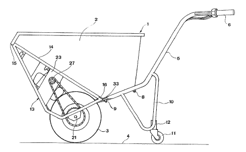
Fig 2 is a side view of a wheelbarrow according to the inven~
Lion provided with support wheels in transport position,
5
Fig ~ is a perspective view obliquely from below of the wheel-
barrow in Fig 1, but without support wheels,
Fig 3 is a perspective view of the frame with the wheel, the
motor and the transmission therebetween of the wheelbarrow
according to Fig 1,
Fig 4 is a perspective view obliquely from above-from the front
of the wheelbarrow in Fig 1, but without support wheels and the
frame shown in Fig 3,
Fig 5 is a perspective view of the frame with the wheel, the
motor and the transmission therebetween of a wheelbarrow
according to a second preferred embodiment of the invention,
Fig 6 is a perspective view obliquely from above of a wheel-
barrow according to the second preferred embodiment of the
invention with the frame according to Fig 5, and
Figs 7a and 7b are perspective views of the two branches of the
wheelbarrow according to Fig 6.
DETAILED DESCRIPTION OF PREFERRED EMBODIMENTS OF THE INVENTION
A wheelbarrow 1 according to a preferred embodiment of the
invention is shown in side view in Fig 7., said barrow compri-
sing a pan 2 open upwardly for receiving a load to be trans-
ported by the barrow, a wheel 3 arranged to bear on the ground
or the underlayer 4 as well as two longitudinal members or
branches 5 extending rearwardly from the pan and having handles
6 for gripping by a person moving the barrow. It is now also
referred to Fig 2. Each longitudinal member is at two places 7
secured to the pan 2 by means of securing means 8, 9, here
screws and nuts. This means that the longitudinal members 5 are
separable from the pan and the rest of the wheelbarrow by
loosening the securing means 8,9. Each longitudinal member 5
has supporting means 10 projecting downwardly, by means of
~~~~(~~l
which the wheelbarrow may rest on the ground 4 when parking it,
in the case that no support wheels have been connected to these
support means. It is shown in Fig 1 how a removable support
wheel 11 may be secured to the respective support means so as
to give the wheel barrow an additional rest on the ground 4 in
the transport position shown in Fig 1. It is then possible that
the supporting means 10 are permanently provided with a sleeve
12, in which a support wheel holder may be inserted and fa-
stened should a support wheel be necessary.
Reference is now parallelly made to Figs 1-3. The wheelbarrow
comprises a frame 13, which is shown more in detail in Fig 3.
This frame 13 is securable with respect to the pan 2 and
separable from the rest of the wheel barrow. The frame has a
profile reminding of a right-angled triangle as seen from the
lateral side, see Fig 1, the hypotenuse bearing against the
under side of a wall 14 inclining forwardly-upwardly from the
bottom of the pan and the two catheters extending downwardly
from the front edge 15 of the pan and the rear end 16 of the
inclining wall 14, respectively. The frame is constructed by
two substantially parallel beam membe7rs 17, which are shaped to
the triangle-like form mentioned, but there is in the practice
no triangle, but a quadrangle, since two bendings have been
made for manufacturing reasons at the "right-angled angle'° of
the triangle, which explains the expression triangle-like. The
two beam members 17 are rigidly connected to each other by a
plate-like cross bar 18. The wheel 3 is at the lower beam
member side 19 through brackets 20 rotatably arranged between
the beam members 17 about a substantially horizontal axis of
rotation 21. The motor 22 is through other cross bars 23
extending between the beam members 17 secured to the frame 13
in front of and above the wheel axle 21 in the transport
position shown in Fig 1.
The motor 22 is preferably an internal combustion engine with
centrifugal clutch and may typically have a power of 1,6 horse
powers. The motor is provided with fuel through a fuel tank 24
7
located between the beam members 27 and which may take for
instance 3 litres. A throttle wire 2~ extends from the carbu-
rator of the motor to one of the handles 6, which functions as
a throttle twist-grip. A gear mechanism 26 is arranged at the
output shaft of the motor so as to change down the rotation
speed, and a gear 28 is arranged at the output shaft 27 of the
gear mechanism. A bigger gear 29 than the gear 28 is secured
with respect to the wheel axle 21 and a chain 30 is laid around
the two gears 28, 29, so that the output shaft 27 by means of
the chain 30 rotates the gear 29 and by that the wheel 3 when
being ratated. The motar 22 may in this way drive the wheel 3
and by that the wheelbarrow forwardly. The wheel 3 is prefer-
ably provided with a free wheel hub, so that the wheelbarrow,
in absence of a motor driving force on the gear 29, may be
rolled forwardly and backwardly by man power without influen-
cing the chain transmission described and by that making such a
movement heavier.
The output shaft 27 of the motor 22 is arranged in front of and
above the wheel axle 21. The position of this output shaft
corresponds in side view (Fig 1) pretty well to the position of
the centre of gravity of the motor, so that this is in the
transport position located at a substantial distance in front
of a vertical plane including the wheel axle 21 in the embodi-
ment shown. The wheel may thanks to this circumstance be
arranged comparatively far to the front with respect to.the pan
2, so that the shortest distance between the bottom of the pan
and the ground 4 will be less than the diameter of the wheel in
said transport position. The pan may by that be so shaped that
it takes a large volume without putting the centre of gravity
of the pan filled with materials in a location at too great a
height above the ground for giving the wheelbarrow a good
stability in the lateral direction.
The frame 13 comprises also a beam 31. bent, which serves to
protect the motor 22 against driving into obstacles. Further-
more, the entire motor 22 and the tank 24 are arranged behind
8
the beam member parts 17 extending downwardly from the front
edge 15 of the wheel barraw, so that these parts protect the
vital parts of the motor against driving into obstacles. The
frame l3 has also a round rod 32 arranged at the front edge of
the beam members 17 in the transport position according to Fig
1, wherein said rod may be a tube and extends substantially
parallelly to the wheel axle 21. An elongated angled bar 33
extending substantially parallelly to the round rod 32 is
arranged between the beam members 17 at the opposite end of the
frame .
The frame 13 with the members connected thereto is secured to
the rest of the wheelbarrow in the following way:
The round rod is first of all introduced into a groove 34
directed downwardly-rearwardly in the direction of the incli-
ning wall 14, said groove being located at the front edge 15 of
the pan on the underside of the wall 1~. The frame is then
pivoted about a pivot axis defined by the round rod 32 in a
counter-clockwise direction as seen in Fig 1 while rotating the
round rod in the groove 34 until the angled bar 33 comes to
bear against tha rear end 1~ of the wall 14 (see Fig 1). The
securing means 9, i.e. the screws and the nuts, have already
been removed from the pan and are after bringing th.e front end
of the longitudinal member 5 under the angle bar passed through
the holes in the longitudinal member and the angle bar so as to
be secured to the bottom of the pan. The frame is now held
fixed to the pan, since the securing of the angle bar prevents
the round rod 32 received in the groove 34 from rotating and
the beam member parts 32 bear against the underside of the
inclining wall 14. A separation of the frame with the wheel and
the motor is achieved in the opposite way. It is then also
possible to remove the cables going to the motor therefrom, so
that the frame may be completely separated from the rest of the
wheelbarrow, but these cable connections may also be main-
tained, should the wish be merely to lay the frame in the pan.
Thus, by the fact that the longitudinal members 5 are not
connected to the wheel axle 21, which is often the case in
~~~~i~~~
conventional wheelbarrows, it is possible to separate the frame
carrying the wheel from the rest of the wheelbarrow in a very
simple way. The wheelbarraw is in Fig 4 shown separated from
the frame shown in Fig 3.
Fig 5 is a view being similar to Fig 3 of the frame with a
driving unit of a wheelbarrow according to a second preferred
embodiment of the invention. parts corresponding functionally
to parts of the first embodiment have for the sake of simpli-
city been provided with the same references. Thus, the whole
driving unit of the wheelbarrow including the wheel 3, the
motor 22, the transmission arranged therebetween with among
others the gear 26 and the chain 30 as well as the fuel tank 24
is also in this second embodiment arranged on the frame 13.
Besides differences between the two frames 13 with the parts
arranged thereon purely related to 'the appearance there are
also some functional differences. A chain shield 36 arranged
for the chain 30 is in Fig 5 partially broken away so as to
illustrate a free wheel mechanism 37 being a part of the
transmission between the wheel 3 and the motor 22. This is
arranged to act between the output shaft 27 from the gear 26
and the wheel 3 itself, so that on moving the wheelbarrow in a
first direction, suitably in the normail moving direction of the
wheelbarrow, with the motor turned off, there is provided a
free rotation of the wheel without any influence on the output
shaft 27 through the transmission, and this free wheel mecha-
nism forms a connection rigid to rotation between the output
shaft 27 and the rest of the transmissian for rotating this
shaft in the same direction as the wheel axle on a wheel
rotation in the opposite direction. The last mentioned circum-
stance is of course a condition for that the motor 22 shall be
able to rotate the wheel 3 in the normal movement direction of
the wheelbarrow when it is turned on. The free wheel mechanism
37 may be constructed in an arbitrary way, but it comprises in
the illustrated case a sleeve 39 arranged externally of the
output shaft 27 and rigid against rotation with respect there-
to, said sleeve being arranged to project into another sleeve
10
40 secured to the gear 28 in engagement with the chain 30. The
inner sleeve 39 secured to the shaft 27 cooperates with the
outer sleeve 40 secured to the gear 28, so that a sleeve 40
rotates without carrying the sleeve 39 and the output shaft 27
along in this rotation on rotation of the gear 28 and by that
the wheel 3 in the counter-clockwise direction as seen in Fig
5, while a rotation of the sleeve 40 with respect to the sleeve
39 in the opposite direction is not possible, but on a clock-
wise rotation of the wheel 3, when the motor is turned off,
i.e. moving the wheelbarrow backyaards, the outer sleeve 40 and
by that the gear 28 will carry the inner sleeve 39 and by that
the output shaft 27 along when rotating. Thus, thanks to the
free wheel mechanism according to the invention it is possible
to easily roll the wheelbarrow forwardly with a small resis-
tance when the motor is turned off, which is an advantage in
inter alia the overall handling of the wheelbarrow, such as
loading and unloading on vehicles etc.
Furthermore, the round rod 32 of the frame according to Fig 3
is in the frame according to Fig 5 replaced by a hollow square
beam 32°. This is just like the round rod arranged to be
inserted into the groove 34 at the front edge of the pan, but
in this case no rotation thereof takes place. It is instead
obtained that the frame is very steadily kept in place by the
hollow beam 32' fitting into the groove 34. Furthermore, the
angle bar 33 is replaced by two brackets 33' provided with
bores and intended to be arranged closer to the central plane
of the pan and which are less exposed to damages.
It is shown in Fig 6 how the frame according to Fig 5 is
secured to the underside of the pan 2 of the wheelbarrow
according to the second embodiment of the invention. The hollow
square beam 32' is pushed into the groove 34 so that the bores
of the brackets 33° arrive just in front of threaded bores in
the underside of the pan, and screwing means 9 is after that
m ~'0~~03~.
tightened so as to make the securing of the frame to the pan
complete. By doing so the branches 5 are at 'the same time
secured to the pan at the same point by inserting the screwing
means 9 also through brackets 41 arranged thereon (see Figs 7a
and 7b).
It appears from Figs 7a and 7b that the part 42 of one of the
branches extending towards the other branch in the state
mounted on the pan is arranged to be at least partially tele-
scopically received in the other part of the other branch in
this state. This is achieved by the prolongation of one of the
branches 5 by an extension 43 with an outer diameter substan-
tially corresponding to the inner diameter of the part 42 of
the other branch for being inserted therein. Thanks to the
telescopical arrangement of the branches with respect to each
other a very high simplicity in securing the branches together
with the frame to the pan as well as a particularly excellent
durability and stability of the branches in the securing region
is obtained. Furthermore, each of the branches has a further
bracket 44 for screwing it tight to the rear wall 45 of the pan
and special support locks 46 for safer parking of the wheel-
barrow, primarily when there is a ria:k for sliding, such as on
inclining ground.
The wheelbarrow according to the invention may be driven in a
very stable way thanks to the location according to the inven-
tion of the wheel and the motor, which makes the low centre of
gravity of the pan with respect to its volume possible. This
wheelbarrow may substantially increase the efficiency in
carrying out different actions, such as building works on rough
ground and in certain cases make it possible to carry out a
many times higher number of transports per working period than
by a wheelbarrow moved by man power. The wheelbarrow according
to the invention may be driven comparatively bluntly also on
ground with a risk for driving into many obstacles thanks to
the motor being protested by the frame and the frame
m ~~~9~~~~
effectively protects the motor against driving into something
and be damaged.
The expression ''that the diameter of the wheel is larger than
the shortest distance between the bottom of the pan and the
ground in said transport position'° is of course meant to be
valid under condition that the wheelbarrow is placed on a plane
ground. The axis parallel to the wheel axle about which the
tilting of the the wheelbarrow takes place on emptying thereof
is in the practice mostly the wheel axle itself. The definition
°'the motor is arranged under the pan°° is intended to
mean that
at least a part of the motor is arranged under the pan, but it
is indeed, possible that a part thereof projects outwardly past
the side ar the front of the pan.
The invention is of course not restricted to 'the preferred
embodiments described above, but many possibilities to modi~-
f:ications thereof should be apparent to a man skilled in the
art without departing from the basic idea of the invention.
It would be possible for the wheelbarrow to have more than one
wheel so as to achieve an increased stability, but this would
probably render the manoeuvrability and the steering of the
wheelbarrow more difficult, especially on an uneven ground.
The longitudinal member of the frame could have another cross
section than circular or square. The longitudinal member could
also be a female member, such as a U-beam, and the stop member
could be a male member of a suitable type.
It is not necessary that the motor is an internal combustion
engine, but it would also be conceivable to provide the wheel-
barrow with an electrical motor and one or mare batteries.
The pan, the longitudinal members as well as the frame of the
wheelbarrow are preferably made of metal, but other materials,
such as hard plastic would also be possible.