Note: Descriptions are shown in the official language in which they were submitted.
WO 92/09892 PGT/GB91/02058
~~~~2~5
1
METHOD OF ASSAY
This invention relates to a method of assay of
chemical, biochemical or biological entities, to devices
for use in such a method, to a method of manufacture of
such devices and to the use of such devices.
There is now a great interest in the development of
assay techniques for the detection and measurement of
the presence of an analyte in a sample, and the various
methods available have been extensively reviewed, for
example in Biosensors: Fundamentals and Applications,
edited by A.P.F. Turner, I. Karube, G.S. Wilson, Oxford
Scientific Publications, 1987. Current techniques,
however, are highly sensitive to temperature, reagent
stability, incubation and development time, and other
conditions and interfering factors which may affect the
level of the signal observed. Accordingly, the
precision of known assay techniques is limited by the
method of calibration, which usually involves carrying
out an assay on a standard sample. For example, for
assays which involve an antibody, the immunological
binding reactions which occur are frequently
irreversible. Thus any calibration steps need to be
carried out using a separate device or devices
(preferably from the same manufacturing batch), which
inevitably introduces errors.
The need for a separate calibration step involving
the use of additional sensing devices can be avoided by
using in the assay a device which is provided with
appropriate reagents disposed in separate zones whereby
the calibration step is effected within the assay
procedure. The use of an assay method wherein a separate
calibration step is effected within the assay procedure
serves two main purposes, namely i) to confirm that the
various reagents used in the assay procedure are
WO 92/09892 PCT/GB91/02058
20g52~5
2
performing according to their specification, and ii) to
define a certain concentration level within the sample
on test, and thereby to compensate for background
interference (e. g. background fluorescence), temperature
and pH changes and other factors originating from the
sample matrix which may alter the level of the observed
signals.
EP-A-0093613 (SYVA) discloses an assay method for
determining the presence of an analyte in a sample by
means of a measurement region and a calibration region.
The method involves the use of a common species in both
of the regions which gives a signal at the measurement
region related to the amount of analyte in the sample,
and a signal at the calibration region independent of
the analyte concentration. The common species is
captured in the calibration region by means of a
different binding reaction to that which takes place in
the measurement region.
The assay method disclosed in EP 0093613 therefore
provides for a separate calibration within the assay and
to a certain extent does serve purpose ii) above.
However such a method of calibration suffers from a
number of disadvantages. The use of a different binding
reaction in the calibration region means that the
behaviour of the two binding reactions (i.e. in the
measurement and calibration regions respectively) will
not be the same in terms of various factors e.g.
susceptibility to pH and temperature, reagent stability
and reagent ageing. The binding reaction in the
calibration region will also be affected differently by
the sample matrix and so no compensation can be made for
changes occurring to the signal arising from the binding
reaction in the measurement region as a result of the
sample matrix. There will also be no check on the
performance of the binding reaction occurring in the
measurement region (c. f. purpose i) above).
Furthermore, the manufacture of devices for such an
. ~:
assay is made more complex by needing two different sets
of reagents.
we have now developed an alternative assay method
which overcomes these disadvantages of the method of EP
0093613 and which still fulfills the purposes i) and ii)
above.
Thus, according to one aspect of the present
invention we provide a method of assay for a ligand in a
sample which method comprises the steps of:
i) incubating the sample, if desired together with one
or more ancillary reagents, in contact with a surface
("the measurement surface") which surface carries an
immobilised reagent ("the measurement reagent")
appropriate to the assay technique employed whereby if
ligand is present in the sample a complex involving said
measurement reagent and said ligand and/or (if present)
said ancillary reagents) is formed giving rise to a
detectable signal which is a first function of the
amount of ligand (if any) present in the sample;
ii) simultaneously or sequentially contacting the
sample, if desired together with one or more ancillary
reagents, with a further surface ("the calibration
surface") onto which is immobilised a reagent ("the
calibration reagent") appropriate to the assay technique
employed, the calibration reagent either being such as
to give rise to a non-zero signal or being such as to
form a complex involving said ligand and/or said
ancillary reagents) whereby any such complex gives rise
to a non-zero signal and is formed as a result of the
interaction of binding sites identical in structure to
those involved in the formation of the aforesaid complex
formed on the measurement surface (or, where no such
complex is formed, which would be formed if ligand were
present) either between the measurement reagent and the
ligand or, where the ligand is not involved in said
complex, between the measurement reagent and said
ancillary reagent(s), the signal being either a second
function of or independent of the amount of ligand (if
any) present in the sample;
iii) optionally simultaneously or sequentially
' . _ ... . . , ' ~'.~T~tu cd ~'~:
.. _ , ,
209524!5 _ : ~ ,~.
1
4
contacting the sample, if desired together with one or
more ancillary reagents, with a further calibration
surface ("the auxiliary calibration surface") onto which
is immobilised a reagent ("the auxiliary calibration
reagent"), the auxiliary calibration reagent being such
as to give rise to a signal (zero or non-zero as herein
defined) which is either a third function of or
independent of the amount of ligand (if any) present in
the sample; and
iv) monitoring the signals arising from the measurement
surface, from the calibration surface and, when present,
from the auxiliary calibration surface by a method
appropriate to the assay technique employed and, by
comparing the signals arising from the aforesaid
surfaces, thereby determining (using an appropriate
algorithm to calibrate the signal arising from the
measurement surface) whether and/or the extent to which
the ligand under assay is present in the sample.
In the embodiments described hereinafter wherein at
the calibration surface there occurs a binding reaction
analogous to that which occurs at the measurement
surface (if ligand is present in the sample) purpose i)
indicated above is achieved i.e. there may be
confirmation that the reagents in the complex which give
rise to the signal have not degraded or that the binding
reactions are occurring satisfactorily i.e. the binding
partners in such reactions have not degraded. Purpose
ii) may also be achieved in these embodiments.
In the embodiments described hereinafter wherein at
the calibration surface the calibration reagent gives
rise to the desired non-zero signal without there being
a binding reaction to any ancillary reagent(s), purpose
ii) indicated above is achieved.
The use of an optional calibration surface
supplements the calibration achieved by the calibration
surface. The auxiliary calibration surface may utilize
similar reagents to those used in the calibration
surface or may utilise reagents wherein binding
reactions occur at the auxiliary calibration surface
.:~ _, ... ~ m,. ,~ ~
2095245
distinct from those which occur at either the
measurement surface or the calibration surface, either
to give a further non-zero signal or a zero-signal as
defined herein.
5 According to a further aspect of the present invention
there is provided a biosensor device suitable for use in
assaying a ligand in a sample by a method of assay as
hereinbefore defined said device comprising a measurement
surface carrying a measurement reagent and a calibration
surface carrying a calibration reagent optionally together
with one or more auxiliary calibration surfaces each
carrying an auxiliary calibration reagent, said measurement
reagent, calibration reagent and auxiliary calibration
reagent each being as defined above.
In step ii) above, where the signal is a second
function of the amount of ligand present in the sample,
this second function is different to the first function
specified in step i). In step iii) above, where the
signal is a third function of the amount of ligand
present in the sample, this third function is different
to the first function specified in step i) and may be
the same as, but is preferably different to, the second
function specified in step ii).
Where an auxiliary calibration surface is present, the
calibration reagent and auxiliary calibration reagent will
be chosen such that the signals arising from the
calibration surface and from the auxiliary calibration
surface are not identical. Such non-identical signals
can arise where the signal arising from the calibration
surface and the signal arising from the auxiliary
calibration surface is the same function of the amount
of ligand present in the sample. One example is where
the calibration reagent and auxiliary calibration
reagent are the same but the amounts of ancillary
reagents) which form a complex with the calibration
reagent and auxiliary calibration reagent differ.
Another example is where the calibration reagent and
auxiliary calibration reagent both give rise to a signal
without the need for an ancillary reagent and are
present in differing amounts. If it is found, despite
_. ...~... ~
.. ; ; ._' ; :~ , ~ ;
WO 92/09892
.CJ ~ ~ PC'T/GB91/02058
6
such a choice of calibration reagent and auxiliary
calibration reagent, that identical signals arise, then
device failure (e.g. due to extremes of sample pH, too
high a sample background signal or reagent degradation)
is indicated and the assay can be rejected; this is a
further advantage of the present invention.
For a qualitative method of assay for a ligand in a
sample, preferably one auxiliary calibration surface is
present. For a semi-quantitative method at least one
auxiliary calibration surface is present. For a
quantitative method, the number of auxiliary calibration
surfaces present is preferably greater than one, more
preferably greater than or equal to four.
The method of assay according to the invention is
applicable to a wide variety of assay techniques
including direct assays, competition assays and sandwich
assays.
The term "direct assay" is used herein to mean an
assay in which no ancillary reagent is required and
hence in which binding of sample ligand to an
appropriate specific binding partner directly modulates
the signal being measured, for example certain assays
using surface plasmon resonance or piezoelectric
biosensors. However, such biosensors sometimes use
labels to enhance their performance (for example as
described in EP-A-276142). The use of such indirect
assay techniques as applied to the method of the present
invention is encompassed by the present application.
The term "zero signal" as used above denotes the
background signal for the assay concerned. The term
"non-zero signal" is to be construed accordingly.
In a direct or sandwich assay the zero signal will
be the signal obtained when no analyte is present. In a
competition assay the zero signal will be the signal
corresponding to the low asymptote of the appropriate
assay curve and will therefore not be the signal
obtained when no analyte is present.
WO 92/09892 ~ o ~ ~ ~ 5 PCT/GB91/02058
7
In direct assays and in sandwich assays the
detectable signal will in general be proportional to the
quantity of ligand present in the sample. In
competition assays, a complex between measurement
reagent and the ancillary reagent will be formed whether
or not ligand is present in the sample but the
detectable signal will depend on the quantity of
ancillary reagent complexed; this will in general be
inversely proportional to the quantity of ligand present
in the sample. The term "competition assay" as used
herein includes within its scope, where the context so
permits, displacement assays, e.g. assays in which the
measurement reagent is pre-complexed with an appropriate
ancillary reagent and this pre-complex is subsequently
incubated with sample whereby at least a portion of any
ligand present in the sample displaces a corresponding
amount of ancillary reagent.
Thus, in ene type of assay in accordance with an
embodiment of the present invention:
in step i) the measurement reagent (or optionally
an ancillary reagent precomplexed with or capable of
forming a complex involving the measurement reagent) is
a specific binding partner for the ligand under assay;
and
in step ii) a ligand analogue is present as an ancillary
reagent and the calibration reagent (or optionally an
ancillary reagent precomplexed with or capable of
forming a complex involving the calibration reagent) is
a specific binding partner for the ligand under assay;
and
in step iii) either a) the auxiliary calibration reagent
and ancillary reagents) are equivalent to the
calibration reagent and ancillary reagents)
respectively defined in step ii) above or b) a ligand
distinct from the ligand under assay is present as an
ancillary reagent and the auxiliary calibration reagent
(or optionally an ancillary reagent precomplexed with or
WO 92/09892 ~ . ~. ~ ~ PCT/G B91 /0258
8
capable of forming a complex involving the auxiliary
calibration reagent) is a specific binding partner for
the ligand distinct from the ligand under assay or c)
the auxiliary calibration reagent is a binding partner
non-specific for the ligand under assay.
In a competition assay according to a further
embodiment of the present invention:
in step i) either a) a ligand analogue is present as an
ancillary reagent and the measurement reagent (or
l0 optionally an ancillary reagent precomplexed with or
capable of forming a complex involving the measurement
reagent) is a specific binding-partner for the ligand
under assay or b) an optionally labelled specific
binding partner for the ligand under assay is present as
an ancillary reagent and the measurement reagent (or
optionally an ancillary reagent precomplexed with or
capable of forming a complex involving the measurement
reagent) is a ligand analogue;
and
in step ii) either a) a ligand analogue is present as an
ancillary reagent and the calibration reagent (or
optionally an ancillary reagent precomplexed with or
capable of forming a complex involving the calibration
reagent) is a specific binding partner for the ligand
under assay or b) an optionally labelled specific
binding partner for the ligand under assay is present as
an ancillary reagent and the calibration reagent (or
optionally an ancillary reagent precomplexed with or
capable of forming a complex involving the calibration
reagent) is a ligand analogue or c) the calibration
reagent gives rise to the desired non-zero signal
without the need for presence of an ancillary reagent;
and
in step iii) either a) the auxiliary calibration reagent
and ancillary reagents) are equivalent to the
calibration reagent and ancillary reagents)
respectively defined in step ii) above or b) an
~.4~~245
WO 92/09892 ~ . PGT/GB91/02058
9
optionally labelled ligand distinct from the ligand
under assay is present as an ancillary reagent and the
auxiliary calibration reagent (or optionally an
ancillary reagent precomplexed with or capable of
forming a complex involving the auxiliary calibration
reagent) is a specific binding partner for the ligand
distinct from the ligand under assay or c) the auxiliary
calibration reagent is a binding partner non-specific
for any ancillary reagents) present or d) the auxiliary
l0 calibration reagent gives rise to the desired zero
signal without the need for the presence of an ancillary
reagent.
In a sandwich assay according to a still further
embodiment of the present invention:
in step i) an optionally labelled specific binding
partner for the ligand under assay is present as an
ancillary reagent and the measurement reagent (or
optionally an ancillary reagent precomplexed with or
capable of forming a complex involving the measurement
reagent) is a further specific binding partner for the
ligand under assay the said further specific binding
partner being directed to an epitope of the ligand under
assay different to the epitope to which the optionally
labelled specific binding partner is directed;
and
in step ii) either a) the calibration reagent (or
optionally an ancillary reagent precomplexed with or
capable of forming a complex involving the calibration
reagent) is a specific binding partner for the ligand
under assay, an optionally labelled specific binding
partner for the ligand under assay is present as an
ancillary reagent and a known amount of the ligand under
assay precomplexed to its optionally labelled specific
binding partner is present as a yet further ancillary
reagent or b) an optionally labelled specific binding
partner for the ligand under assay is present as an
ancillary reagent and the calibration reagent (or
WO 92/09892 '~ ~ ~ ~ , ~ PCT/GB91/02058
l0
optionally an ancillary reagent precomplexed with or
capable of forming a complex involving the calibration
reagent) is a known amount of the ligand under assay
precomplexed to its immobilized specific binding partner
or c) the calibration reagent gives rise to the desired
non-zero signal without the need for presence of an
ancillary reagent;
and
in step iii) either a) the auxiliary calibration reagent
and ancillary reagents) are equivalent to the
calibration reagent and ancillary reagents)
respectively defined in step ii) above or b) a ligand
distinct from the ligand under assay is present as an
ancillary reagent and the calibration reagent (or
optionally an ancillary reagent precomplexed with or
capable of forming a complex involving the calibration
reagent) is an optionally labelled specific binding
partner for the ligand distinct from the ligand under
assay or c) the auxiliary calibration reagent is an
optionally labelled binding partner non-specific for any
ancillary reagents) present or d) the auxiliary
calibration reagent gives rise to the desired zero
signal without the need for the presence of an ancillary
reagent.
The term "ligand analogue" as used herein denotes a
species which is capable of binding to the same epitopic
site of the same specific binding partner as the ligand
under assay, and includes inter alia within its scope a
known amount of the ligand under assay or a labelled
aliquot of the said ligand.
A wide variety of devices may be used to perform
the method of the present invention including for
example dipstick or 'test-strip' biosensors, devices
using a 'sample flow-through' configuration or devices
employing sample containment. Examples of biosensors
which may be used in the method of the present invention
include sensors involving surface plasmon resonance,
WO 92/09892 PCT/GB91/02058
~~9~~~5
11
piezoelectric and total internal reflectance techniques.
A preferred device to carry out the method of the
present invention is a capillary fill device, especially
a fluorescence capillary fill device, for example the
type of device described in EP-A-171148 or in
WO-90/14590. Such capillary fill devices may be used
singly or in a suitable holder such as described in WO-
90/1830.
As described in EP-A-171148, a capillary fill
device (hereinafter CFD) typically consists of two
plates of transparent material, e.g. glass, separated by
a narrow gap or cavity. One plate acts as an optical
waveguide and carries an immobilised reagent appropriate
to the test to be carried out in the device. As
described in WO-90/14590, the other transparent plate
can carry on its surface remote from the cavity a layer
of light-absorbing or opaque material. For use in a
competition assay, the immobilised reagent may for
example be a specific binding partner to the ligand
desired to be detected and one of the plates may carry a
dissoluble reagent comprising ligand analogue, labelled
with a fluorescent dye (the ancillary reagent). When a
sample is presented to one end of the CFD it is drawn
into the gap by capillary action and dissolves the
ancillary reagent. In a competition assay for an
antigen, the fluorescently labelled antigen analogue
will compete with sample antigen for the limited number
of antibody binding sites immobilised on the waveguide.
Because the capillary gap is narrow (typically about 100
microns) the reaction will generally go to completion in
a short time, possibly less than 5 minutes depending
upon the sample matrix and antibody affinity. Thus for
a competition assay, the amount of fluorescently
labelled antigen which becomes indirectly bound to the
waveguide by virtue of complex formation will be
inversely proportional to the concentration of antigen
in the sample. In a sandwich assay, the waveguide will
WO 92/09892
PCT/GB91 /02058
12
carry a specific binding partner for the ligand desired
to be detected and either one of the plates will carry a
dissoluble reagent comprising a further specific binding
partner labelle3 with a fluorescent dye (the ancillary
reagent). In a sandwich immunoassay for an antigen, a
sample antigen will form a sandwich complex with a
fluorescently labelled antibody and an antibody
immobilised on the waveguide. Thus, for a sandwich
immunoassay, the amount of fluorescently labelled
antibody which becomes indirectly bound to the waveguide
by virtue of complex formation will be directly
proportional to the concentration of antigen in the
sample.
The term "antigen" as used herein will be
understood to include both antigenic species (for
example, proteins, bacteria, bacterial fragments, cells,
cell fragments and viruses) and haptens which may be
rendered antigenic under suitable conditions.
According to a preferred embodiment of the device
according to the invention we provide a specifically-
reactive sample-collecting and testing device for use in
an assay for a ligand, possessing a cavity or cavities,
one surface of the or each cavity having three zones I,
II and III mutually separated and each zone carrying a
layer comprising, in releasable form, a reagent suitable
for the desired assay, said surface being a surface of a
first solid plate fashioned of transparent material,
wherein the wall of the or each cavity opposite to said
first plate comprises a second plate fashioned of
transparent material and adapted to act as a light-
transmissive waveguide, the second plate having on its
surface adjacent the cavity three zones IV, V and VI
corresponding in orientation to the aforementioned zones
I, II and III respectively, each of zones IV, V and VI
carrying a layer comprising an immobilised reagent
suitable for the desired assay. The first plate
advantageously carries on its external face an opaque
WO 92/09892 ~ ~ ~ ~ ~, ~ J PCf/GB91/02058
13
coating.
For convenience, in the more detailed description
of such a device, the reagents carried by the
aforementioned zones I, II, III, IV, V and VI will be
designated as follows:
Zone Reaaent
I. (top plate) X (ancillary reagent in
soluble, releasable form)
II. (top plate) Y (ancillary reagent in
soluble, releasable form)
III. (top plate) Z (ancillary, reagent in
soluble, releasable form)
IV. (baseplate) A (immobilised reagent)
V. (baseplate) B (immobilised reagent)
VI.' (baseplate) C (immobilised reagent)
The terms "top plate" and "baseplate" are used
purely for convenience of description and their use is
not intended to limit in any way the configuration in
which the device may be used.
The arrangement of the aforementioned zones is such
that zone I is paired together with zone IV, zone II is
paired together with zone V and zone III is paired
together with zone VI, such that one of said pairs
provides the region of the device which gives rise to a
measurement of the amount of ligand it is desired to
assay (the "measurement region") and the other two pairs
provide regions of the device which give rise to
measurements which can be used as control or calibration
parameters (the "calibration regions").
CFDs for use in the method of the invention may if
desired contain more than one auxiliary calibration
zone; and may if desired contain multiple assay zones
enabling simultaneous or sequential assays for different
ligands in the same sample to be conducted. For
example, the device could contain a first measurement
WO 92/09892 PCT/GB91/02058
2~9.~245
14
zone and a calibration zone as herein defined for one
assay together with a further measurement zone for a
different assay. The calibration zone would also serve
as a calibration for the further measurement zone
although such calibration would differ from that for the
first measurement zone. Additionally, auxiliary
calibration zones could be included as desired.
The identities of the reagents X, Y, Z, A, B and C
will depend both on the ligand it is desired to assay
and on the assay methodology. The reagents carried in
the zones on the first transparent plate may be
contained within a dissoluble layer of a suitable
material. After deposition of the soluble reagent, a
capping layer e.g. polyvinyl alcohol (PVA) may be placed
upon the reagent, which capping layer delays the
dissolution of the reagent for a few seconds after the
addition of the sample to the device. This is to
prevent the reagents being washed from one zone to
another thereby precluding an accurate assay. The
cavity or cavities of the device are preferably of a
dimension small enough to enable sample liquid to be
drawn into the cavity by capillary action, although any
other method of filling said cavities may be employed.
The zones on the first transparent plate and thereby the
corresponding zones on the second transparent plate may
be arranged either in tandem or in any other geometrical
arrangement which maintains the integrity of the zones.
In a first embodiment of the device suitable for
use in a direct assay, the reagent X may be absent; the
reagent Y may be a known amount of the ligand under
assay, and the reagent Z may be absent. In this
embodiment reagent A may be a reactive species
immobilised on the surface of the plate being a specific
binding partner for the ligand under assay; reagent B
may be identical to reagent A; and reagent C may be a
reactive species immobilised on the surface of the plate
being a binding partner non-specific for the ligand
WO 92/09892 ~ ~ '~ PCT/G B91 /02058
~~~~~,4
under assay.
In a second embodiment of the device suitable for
use in a direct assay, the reagent X may be absent. In
such an embodiment, the reagent Y may be a known amount
5 of the ligand under assay together with an amount of a
specific binding partner for the ligand under assay such
that a fully saturated complex exists. In such an
embodiment, the reagent Z may be absent. Thus, zone II
carries a known amount of a ligand bound to its specific
10 binding partner. Reagent A may be a reactive species
immobilised on the surface of the plate being a specific
binding partner for the ligand under assay; reagent B
may be a reactive species immobilised on the surface of
the plate being a specific binding partner for the
15 reagent Y; and reagent C may be a reactive species
immobilised on the surface of the plate being a binding
partner non-specific for the ligand under assay.
In a first embodiment of the device suitable for
use in a competition type assay, the reagent X may be a
fluorescently labelled ligand analogue together with a
known amount of a specific binding partner for the
sample ligand under assay. In such an embodiment, the
reagent Y may be a fluorescently labelled ligand
analogue together with an amount of a specific binding
partner for the sample ligand under assay such that a
fully saturated complex exists. In such an embodiment,
the reagent Z may be a known amount of ligand under
assay together with an amount of a specific binding
partner for the ligand under assay such that a fully
saturated complex exists. Thus zone I carries a known
amount of both fluorescently labelled ligand analogue
and its specific binding partner; zone II carries a
known amount of a fluorescently labelled ligand analogue
bound to its specific binding partner; whilst zone III
carries a known amount of the ligand under assay bound
to its specific binding partner; reagent A may be a
reactive species immobilised on the surface of the
WO 92/09892 PCT/GB91/02058
2095245
1~
plate, being a specific binding partner for the specific
binding partner of the sample ligand under assay; and
both reagent B and reagent C may be equivalent to
reagent A.
In a second embodiment of the device suitable for
use in a competition type assay, the reagent X may be a
fluorescently labelled ligand analogue; the reagent Y
may be the reagent X together with a known amount of
ligand itself; and the reagent Z may be a fluorescently
labelled ligand analogue together with an amount of a
specific binding partner for the sample ligand under
assay such that a fully saturated complex exists. Thus
zone I carries a known amount of a fluorescently
labelled ligand analogue; zone II carries known amounts
of both fluorescently labelled ligand analogue and the
ligand under assay; whilst zone III carries a known
amount of a fluorescently labelled ligand analogue bound
to its specific binding partner. Reagent A may be a
reactive species immobilised on the surface of the
plate, being a specific binding partner for the sample
ligand under assay; reagent B may be equivalent to
reagent A; and reagent C may be a reactive species
immobilised on the surface of the plate, being a
specific binding partner for the specific binding
partner of the sample ligand under assay.
In a third embodiment of the device suitable for
use in a competition type assay, the reagent X may be a
fluorescently labelled ligand analogue. In such an
embodiment, the reagent Y may be absent and the reagent
Z may be equivalent to the reagent X. Thus zone I and
zone III both carry a known amount of fluorescently
labelled ligand analogue. Reagent A may be a reactive
species immobilised on the surface of the plate, being a
specific binding partner for the sample ligand under
assay; reagent B may be a reactive species immobilised
on the surface of the plate, being a fluorescently
labelled binding partner which may be either specific or
WO 92/09892 ~ ~ ~'~ ~ PCT/GB91/02058
17
non-specific for the sample ligand under assay; and
reagent C may b~ a reactive species immobilised on the
surface of the plate, being a binding partner non-
specific for the sample ligand under assay.
In a fourth embodiment of the device suitable for
use in a competition type assay, the reagent X may be a
fluorescently labelled ligand analogue. In such an
embodiment, the reagent Y may be a fluorescently
labelled ligand analogue together with an amount of a
specific binding partner for the sample ligand under
assay such that a fully saturated complex exists. In
such an embodiment, the reagent Z may be the ligand
under assay together with an amount of a specific
binding partner for the ligand under assay such that a
fully saturated complex exists. Thus zone I carries a
known amount of both fluorescently labelled ligand
analogue and its specific binding partner; zone II
carries a known amount of a fluorescently labelled
ligand analogue bound to its specific binding partner;
whilst zone III carries a known amount of the ligand
under assay bound to its specific binding partner.
Reagent A may be a reactive species immobilised on the
surface of the plate, being a specific binding partner
for the sample ligand under assay; and both reagent B
and reagent C may be equivalent to reagent A.
In a fifth embodiment of the device suitable for
use in a competition-type assay, the reagent X may be a
fluorescently labelled ligand analogue. In such an
embodiment, reagent Y may be absent and the reagent Z
may be absent or may be equivalent to reagent X. Thus
zone I and optionally zone III both carry a known amount
of a fluorescently labelled ligand analogue. Reagent A
may be a reactive species immobilized on the surface of
the plate, being a specific binding partner for the
sample ligand under assay; reagent B may be the same as
reagent A but together with an amount of reagent X such
that either a fully saturated complex of reagent A with
WO 92/09892 PCT/GB91/02058
~~~~~~5
is
reagent X exists or that said complex forms under the
operation of the assay; and reagent C may be same as
reagent A but together with an amount of the sample
ligand under assay such that either a fully saturated
complex of reagent A with the sample ligand under assay
exists or that said complex forms under the operation of
the assay and when reagent Z is present, additionally
reagent A together with an amount of a fluorescently
labelled ligand analogue such that either a fully
saturated complex of reagent A with the ligand analogue
exists or that said complex forms under the operation of
the assay is present.
In a sixth embodiment of the device suitable for
use in a competition type assay, the reagent X may be a
fluorescently labelled ligand analogue. In such an
embodiment, the reagent Y may be a fluorescently
labelled ligand analogue together with an amount of a
specific binding partner for the sample ligand under
assay such that a fully saturated complex exists and the
ligand under assay together with an amount of a specific
binding partner for the sample ligand under assay such
that a fully saturated complex exists. In such an
embodiment, reagent Z may be equivalent to reagent X.
Thus, zone I carries a known amount of fluorescently
labelled ligand analogue; zone II carries a known amount
of a fluorescently labelled ligand analogue bound to its
specific binding partner together with a known amount of
the ligand under assay bound to its specific binding
partner; whilst zone III carries the same reagent as
zone I. Reagent A may be a reactive species immobilised
on the surface of the plate, being a specific binding
partner for the sample ligand under assay; reagent B may
be a reactive species immobilised on the surface of the
plate, being a specific binding partner for the specific
binding partner of the sample ligand under assay; and
reagent C may be a reactive species immobilised on the
surface of the plate, being a binding partner non-
WO 92/09892 PCT/GB91/02058
209~~45
19
specific for the sample ligand under assay.
The measurement regions and some of the calibration
regions in the embodiments hereinbefore described are
such that the species which becomes bound to the
immobilised reagent on the measurement or calibration
surface is bound indirectly via one intervening moiety.
Further embodiments wherein no intervening moiety is
present and those wherein more than one intervening
moiety is present suggest themselves and are equally
within the scope of the present invention. The
following fourteen embodiments relate to the case where
no intervening moiety is present i.e. the species
becomes bound directly to the immobilised reagent on the
measurement or calibration surface.
In a seventh embodiment of the device suitable for
use in a competition type assay, the reagent X may be a
fluorescently labelled ligand analogue. In such an
embodiment, the reagent Y may be the reagent X together
with the ligand itself and the reagent Z may be
equivalent to the reagent X or may be absent. Thus,
zone I carries a known amount of a fluorescently
labelled ligand analogue; zone II carries known amounts
of both fluorescently labelled ligand analogue and the
ligand under assay; whilst when reagent Z is present
zone III carries the same reagent as zone I. In such an
embodiment, reagent A may be a reactive species
immobilized on the surface of the plate, being a
specific binding partner for the sample ligand under
assay; reagent B may be equivalent to reagent A; and
reagent C may be reagent A together with an amount of
reagent X such that either a fully saturated complex of
reagent A with reagent X exists or that said complex
forms under the operation of the assay.
In an eighth embodiment of the device suitable for
use in a competition-type assay, the reagent X may be a
fluorescently labelled ligand analogue. In such an
embodiment, the reagent Y may be the same as reagent X
WO 92/09892 ~ ~ ~ ~ ~ ~ ~ PCT/GB91/02058
but together with the ligand itself and the reagent Z
may be equivalent to the reagent X. Thus zone I carries
a known amount of a fluorescently labelled.ligand
analogue; zone II carries known amounts of both
5 fluorescently labelled ligand analogue and the ligand
under assay; whilst zone III carries the same reagent as
zone I; reagent A may be a reactive species immobilized
on the surface of the plate, being a specific binding
partner for the sample ligand under assay; reagent B may
10 be equivalent to reagent A; and reagent C may be reagent
A together with an amount of the sample ligand under
assay such that either a fully saturated complex of
reagent A with the sample ligand under assay exists or
that said complex forms under the operation of the
15 assay.
In a ninth embodiment of the device suitable for
use in a competition type assay, the reagent X may be a
fluorescently labelled ligand analogue. In such an
embodiment, the reagent Y may be same as the reagent X
20 but together with the ligand itself and the reagent Z
may be equivalent to the reagent X. Thus, zone I
carries a known amount of a fluorescently labelled
ligand analogue; zone II carries known amounts of both
fluorescently labelled ligand analogue and the ligand
under assay; whilst zone III carries the same reagent as
zone I; reagent A may be a reactive species immobilized
on the surface of the plate, being a specific binding
partner for the sample ligand under assay; and reagent B
may be equivalent to reagent A; and reagent C may be a
reactive species immobilized on the surface of the
plate, being a specific binding partner for a ligand
other than the sample ligand under assay, optionally
together with an amount of the ligand for which it is a
specific binding partner such that a fully saturated
complex of said reactive species with its specific
binding partner exists or that said complex forms under
the operation of the assay.
WO 92/09892 ~ PCT/GB91/02058
21
In a tenth embodiment of the device suitable for
use in a competition type assay, the reagent X may be a
fluorescently labelled ligand analogue. In such an
embodiment, the reagent Y may be the same as reagent X
but together with the ligand itself and the reagent Z
may be equivalent to the reagent X. Thus, zone I
carries a known amount of a fluorescently labelled
ligand analogue; zone II carries known amounts of both
fluorescently labelled ligand analogue and the ligand
under assay; whilst zone III carries the same reagent as
zone I; reagent A may be a reactive species immobilized
on the surface of the plate, being a specific binding
partner for the sample ligand under assay; and reagent B
may be equivalent to reagent A; and reagent C may be a
reactive species immobilized on the surface of the
plate, being a specific binding partner for a ligand
other than the sample ligand under assay, optionally
together with an amount of a fluorescently labelled
analogue of a ligand for which it is a specific binding
partner such that either a fully saturated complex of
said reactive species with said analogue of the ligand
that is its specific binding partner exists or that said
complex forms under the operation of the assay.
In an eleventh embodiment of the device suitable
for use in a competition-type assay, the reagent X may
be a fluorescently labelled ligand analogue. In such an
embodiment, the reagent Y may be same as the reagent X
but together with the ligand itself. In such an
embodiment, the reagent Z may be a ligand analogue, said
ligand being distinct from the sample ligand and not
being a specific binding partner for the reactive
species for which the sample ligand is a specific
binding partner. Thus zone I carries a known amount of
a fluorescently labelled ligand analogue; zone II
carries known amounts of both the fluorescently labelled
ligand analogue and the ligand under assay; whilst zone
III carries a known amount of a fluorescently labelled
WO 92/09892 PCT/GB91/02058
X095245
22
ligand analogue distinct from the ligand analogue used
in zone I; reagent A may be a reactive species
immobilized on the surface of the plate, being a
specific binding partner for the sample ligand under
assay; and both reagent B and reagent C may be
equivalent to reagent A.
In a twelfth embodiment of the device suitable for
use in a competition-type assay, the reagent X may be a
fluorescently labelled ligand analogue. In such an
embodiment, both the reagent Y and the reagent Z may be
equivalent to reagent X. Thus all three zones I, II and
III carry a known amount of a fluorescently labelled
ligand analogue; reagent A may be a reactive species
immobilized on the surface of the plate, being a
specific binding partner for the sample ligand under
assay; reagent B may be the same as reagent A but
together with an amount of reagent X such that either a
fully saturated preformed complex of reagent A with
reagent X exists or that said complex forms under the
operation of the assay; and reagent C may be a reactive
species immobilized on the surface of the plate, being a
specific binding partner for a ligand other than the
sample ligand under assay, optionally together with an
amount of the ligand for which it is a specific binding
partner such that a fully saturated complex of said
reactive species with its specific binding partner
exists or that said complex forms under the operation of
the assay.
In a thirteenth embodiment of the device suitable
for use in a competition-type assay, the reagent X may
be a fluorescently labelled ligand analogue. In such an
embodiment, the reagent Y may be equivalent to the
reagent X. In such an embodiment, the reagent Z may be
a fluorescently labelled ligand analogue, said ligand
being distinct from the sample ligand and being a
binding partner non-specific for the reactive species
for which the sample ligand is a specific binding
WO 92/09892 ~ ~ ~ ~ ~ PGT/GB91/02058
23
partner. Thus zone I and zone II both carry a known
amount of a fluorescently labelled ligand analogue;
whilst zone III carries a known amount of a
fluorescently labelled ligand analogue distinct from the
ligand analogue used in zone I; reagent A may be a
reactive species immobilized on the surface of the
plate, being a specific binding partner for the sample
ligand under assay; reagent B may be the same as reagent
A but together with an amount of reagent X such that
either a fully saturated complex of reagent A with
reagent X exists or that said complex forms under the
operation of the assay; and reagent C may be the same as
reagent A optionally together with an amount of the
sample ligand under assay such that either a fully
saturated complex of reagent A with the sample ligand
under assay exists or that said complex forms under the
operation of the assay.
In a fourteenth embodiment of the device suitable
for use in a competition-type assay, the reagent X may
be a fluorescently labelled ligand analogue. In such an
embodiment, the reagent Y may be absent or may be
equivalent to reagent X and the reagent Z may be
equivalent to reagent X. Thus zones I and III and
optionally zone II carry a known amount of a
fluorescently labelled ligand analogue; reagent A may be
a reactive species immobilized on the surface of the
plate, being a specific binding partner for the sample
ligand under assay; reagent B may be a fluorescently
labelled reactive species immobilized on the surface of
the plate, optionally being a specific binding partner
for the sample ligand under assay; and reagent C may be
reagent A together with an amount of the sample ligand
under assay such that either a fully saturated complex
of reagent with the sample ligand under assay exists or
that said complex forms under the operation of the
assay.
In a fifteenth embodiment of the device suitable
WO 92/09892 ~ O 9 ~ 2 4 ~ PCT/GB91/02058
24
for use in a competition-type assay, the reagent X may
be a fluorescently labelled ligand analogue. In such an
embodiment, the reagent Y may be absent and the reagent
Z may be equivalent to reagent X. Thus zones I and III
carry a known amount of a fluorescently labelled ligand
analogue; reagent A may be a reactive species
immobilized on the surface of the plate, being a
specific binding partner for the sample ligand under
assay; reagent B may be a fluorescently labelled
reactive species immobilized on the surface of the
plate, optionally being a specific binding partner for
the sample ligand under assay; and reagent C may be a
reactive species immobilized on the surface of the
plate, being a specific binding partner for a ligand
other than the sample ligand under assay, optionally
together with an amount of the ligand for which it is a
specific binding partner such that either a fully
saturated complex of said reactive species with the
ligand that is its specific binding partner exists or
that said complex forms under the operation of the
assay.
In a sixteenth embodiment of the device suitable
for use in a competition-type assay, the reagent X may
be a fluorescently labelled ligand analogue. In such an
embodiment, the reagent Y may be the same as reagent X
but together with the ligand under assay. In such an
embodiment, the reagent Z may be the reagent X together
with an amount of the ligand under assay, said amount
being different to that present in reagent Y. Thus
zone I carries a known amount of a fluorescently
labelled ligand analogue; both zone II and zone III
carry known amounts of both fluorescently labelled
ligand analogue and the ligand under assay; reagent A
may be a reactive species immobilized on the surface of
the plate, being a specific binding partner for the
sample ligand under assay; and both reagent B and
reagent C may be equivalent to reagent A.
WO 92/09892 ~ ~ ~ ~ ~ ~ ~ PCT/GB91/02058
In a seventeenth embodiment of the device suitable
for use in a competition type assay, the reagent X may
be a fluorescently labelled specific binding partner for
the ligand under assay. In such an embodiment, the
5 reagent Y may be a fluorescently labelled specific
binding partner for the ligand under assay and a
fluorescently labelled specific binding partner for the
ligand under assay together with an amount of the ligand
under assay such that a fully saturated complex exists.
10 In such an embodiment, the reagent Z may be a
fluorescently labelled binding partner non-specific for
the ligand under assay. Thus, zone I carries a known
amount of fluorescently labelled specific binding
partner for the ligand under assay; zone II carries a
15 known amount of fluorescently labelled specific binding
partner for the ligand under assay bound to the ligand
under assay together with a known amount of the
unlabelled specific binding partner for the ligand under
assay; whilst zone III carries a known amount of a
20 fluorescently labelled binding partner non-specific for
the ligand under assay; reagent A may be a reactive
species immobilised on the surface of the plate, being
the ligand under assay; and reagent B and reagent C may
be identical to reagent A.
25 In an eighteenth embodiment of the device suitable
for use in a competition type assay, the reagent X rnay
be a fluorescently labelled specific binding partner for
the ligand under assay. In such an embodiment, the
reagent Y may be absent. In such an embodiment, the
reagent Z may be a fluorescently labelled specific
binding partner for the ligand under assay together with
an amount of the ligand under assay such that a fully
saturated complex exists and a fluorescently labelled
ligand analogue, said ligand not being the ligand under
assay. Thus, zone I carries a known amount of
fluorescently labelled specific binding partner for the
ligand under assay; ;whilst zone III carries a known
WO 92/09892 ~ ~ , PCT/GB91/02058
26
amount of unlabelled specific binding partner for the
ligand under assay bound to the ligand under assay
together with a fluorescently labelled ligand analogue,
the ligand being distinct from the ligand under assay;
reagent A may be a reactive species immobilised on the
surface of the plate, being the ligand under assay; and
reagent B may be a reactive species immobilised on the
surface of the plate, being a fluorescently labelled
ligand analogue; and reagent C may be a reactive species
immobilised on the surface of the plate, being a
specific binding partner for the ligand under assay.
In a nineteenth embodiment of the device suitable
for use in a competition type assay, the reagent X may
be a fluorescently labelled specific binding partner for
the ligand under assay. In such an embodiment, the
reagent Y may be a known amount of the ligand under
assay together with its specific binding partner such
that a fully saturated complex exists at a specific
ratio (e.g. 1:2). In such an embodiment, the reagent Z
may be a fluorescently labelled binding partner non-
specific for the ligand under assay. Thus zone I
carries a known amount of fluorescently labelled
specific binding partner for the ligand under assay;
zone II carries a known amount of fluorescently labelled
specific binding partner for the ligand under assay
bound to the ligand under assay; whilst zone III carries
a known amount of a fluorescently labelled binding
partner non-specific for the ligand under assay; reagent
A may be a reactive species immobilised on the surface
of the plate, being the ligand under assay; and reagent
B may either be a reactive species immobilised on the
surface of the plate, being a specific binding partner
for the ligand under assay or may be equivalent to
reagent A; and reagent C may be equivalent to reagent A.
In a twentieth embodiment of the device suitable
for use in a competition type assay, the reagent X may
be a fluorescently labelled specific binding partner for
WO 92/09892 ~ ~ 5 ~,~ ~ C~ PCT/GB91/02058
27
the ligand under assay. In such an embodiment, the
reagent Y may be absent. In such an embodiment, the
reagent Z may be a fluorescently labelled binding
partner non-specific for the ligand under assay. Thus
zone I carries a known amount of fluorescently labelled
specific binding partner for the ligand under assay;
whilst zone III carries a known amount of a
fluorescently labelled binding partner non-specific for
the ligand under assay; reagent A may be a reactive
species immobilised on the surface of the plate, being
the ligand under assay; and reagent B may be a reactive
species immobilised on the surface of the plate, being
the ligand under assay, together with a fluorescently
labelled specific binding partner for the ligand under
assay such that either a preformed complex of the ligand
under assay with its specific binding partner exists or
that said complex forms under the operation of the
device; and reagent C may be identical to reagent A.
In the above embodiments of devices suitable for
use in competition assays, where one of the reagents is
a fluorescently labelled ligand analogue this may
conveniently be a fluorescently labelled aliquot of the
ligand under assay.
In a first embodiment of the device suitable for
use in a sandwich-type assay, the reagent X may be a
fluorescently labelled specific binding partner for the
ligand under assay, whilst reagent Y may be a fully
saturated complex of reagent X and a known amount of the
ligand itself. In such an embodiment, the reagent Z may
be a fluorescently labelled binding partner non-specific
for the ligand under assay. Thus, zone I carries a
known amount of a fluorescently labelled specific
binding partner; zone II carries a known amount of the
fluorescently labelled specific binding partner bound to
the ligand under assay; whilst zone III carries a known
quantity of a binding partner non-specific for the
ligand under assay carrying the same fluorescent label
WO 92/09892 PCT/GB91/02058
X095245
28
as reagent X; reagent A may be a reactive species
immobilized on the surface of the plate, being a
specific binding partner for the sample ligand under
assay; and both reagent B and reagent C may be identical
to reagent A.
In a second embodiment of the device suitable for
use in a sandwich-type assay, the reagent X may be a
fluorescently labelled specific binding partner to the
ligand under assay, whilst reagent Y may be a fully
saturated complex of reagent X and a known amount of the
ligand itself. In such an embodiment, the reagent Z may
be identical to the reagent X. Thus zone I carries a
known amount of a fluorescently labelled specific
binding partner to the ligand under assay; zone II
carries a known amount of the fluorescently labelled
specific binding partner bound to the ligand under
assay; whilst zone III carries the same reagent as zone
I; reagent A may be a reactive species immobilized on
the surface of the plate, being a specific binding
partner for the sample ligand under assay; and reagent B
may be identical to reagent A; and reagent C may be a
reactive species immobilized on a surface of the plate,
being a specific binding partner for a ligand other than
the sample ligand under assay, optionally together with
an amount of ligand for which it is a specific binding
partner such that either a fully saturated complex of
said reactive species with the ligand that is its
specific binding partner exists or that said complex
forms under the operation of the assay.
In a third embodiment of the device suitable for
use in a sandwich-type assay, the reagent X may be a
fluorescently labelled specific binding partner to the
ligand under assay. In such an embodiment, the reagent
Y may be absent. In such an embodiment, the reagent Z
may be a fluorescently labelled specific binding partner
for the ligand under assay together with the ligand
under assay in a fully saturated complex. Thus, zone I
WO 92/09892 PCT/GB91/02058
~t~~~~45
carries a known amount of a fluorescently labelled
specific binding partner for the ligand under assay;
whilst zone III carries a known amount of a
fluorescently labelled specific binding partner bound to
the ligand under assay; reagent A may be a reactive
species immobilised on the surface of the plate, being a
specific binding partner for the ligand under assay;
reagent B may be a fluorescently labelled reactive
species immobilised on the surface of the plate,
optionally a specific binding partner for the sample
ligand under assay; and reagent C may be reagent A
together with an amount of the ligand under assay such
that a full saturated complex exists.
In a fourth embodiment of the device suitable for
use in a sandwich-type assay, the reagent X may be a
fluorescently labelled specific binding partner to the
ligand under assay. In such an embodiment, the reagent
Y may be absent. In such an embodiment, the reagent Z
may be a fluorescently labelled binding partner non-
specific for the ligand under assay. Thus, zone I
carries a known amount of a fluorescently labelled
specific binding partner for the ligand under assay;
whilst zone III carries a known quantity of a
fluorescently-labelled binding partner non-specific for
the ligand under assay; reagent A may be a reactive
species immobilised on the surface of the plate, being a
specific binding partner for the ligand under assay;
reagent B may be a fluorescently labelled reactive
species immobilised on the surface of the plate,
optionally a specific binding partner for the sample
ligand under assay; and reagent C may be identical to
reagent A.
In a fifth embodiment of the device suitable for
use in a sandwich-type assay, the reagent X may be a
fluorescently labelled specific binding partner to the
ligand under assay. In such an embodiment, the reagent
Y may be a fluorescently labelled specific binding
WO 92/09892 PCT/GB91/02058
zo9524~
partner for the ligand under assay together with an
amount of the ligand under assay such that a fully
saturated complex exists and a further fluorescently
labelled specific binding partner for the ligand under
5 assay. In such an embodiment, the reagent Z may be a
fluorescently labelled binding partner non-specific for
the ligand under assay. Thus, zone I carries a known
amount of a fluorescently labelled specific binding
partner for the ligand under assay; zone II carries a
10 known amount of a fluorescently-labelled specific
binding partner bound to the ligand under assay together
with a known amount of the fluorescently labelled
specific binding partner for the ligand under assay;
whilst zone III carries a known quantity of a
15 fluorescently-labelled binding partner non-specific for
the ligand under assay; reagent A may be a reactive
species immobilised on the surface of the plate, being a
specific binding partner for the ligand under assay; and
reagent B and reagent C may both be identical to reagent
20 A.
In a sixth embodiment of the device suitable for
use in a sandwich-type assay, the reagent X may be a
fluorescently labelled specific binding partner to the
ligand under assay. In such an embodiment, the reagent
25 Y may be a fluorescently labelled specific binding
partner for the ligand under assay together with an
amount of the ligand under assay in a fully saturated
complex and a further specific binding partner for the
ligand under assay together with an amount of the ligand
30 under assay in a fully saturated complex. In such an
embodiment, the reagent Z may be a fluorescently
labelled binding partner non-specific for the ligand
under assay. Thus, zone I carries a known amount of a
fluorescently labelled specific binding partner for the
ligand under assay; zone II carries a known amount of
fluorescently-labelled specific binding partner bound to
the ligand under assay together with a known amount of
WO 92/09892 PCT/GB91/02058
~U95245 31
unlabelled specific binding partner bound to the ligand
under assay; whilst zone III carries a known quantity of
a fluorescently-labelled binding partner non-specific
for the ligand under assay; reagent A may be a reactive
species immobilised on the surface of the plate, being a
specific binding partner for the ligand under assay; and
reagent B and reagent C may both be identical to reagent
A.
In a seventh embodiment of the device suitable for
use in a sandwich-type assay, the reagent X may be a
fluorescently labelled specific binding partner to the
ligand under assay. In such an embodiment, the reagent
Y may be absent. In such an embodiment, the reagent Z
may be a fluorescently labelled binding partner non-
specific for the ligand under assay. Thus, zone I
carries a known amount of a fluorescently labelled
specific binding partner for the ligand under assay;
whilst zone III carries a known quantity of a
fluorescently-labelled binding partner non-specific for
the ligand under assay; reagent A may be a reactive
species immobilised on the surface of the plate, being a
specific binding partner for the ligand under assay; and
reagent B may be a reactive species immobilised on the
surface of the plate being a specific binding partner
for the ligand under assay together with an amount of
the ligand under assay and an amount of a fluorescently
labelled specific binding partner for the ligand under
assay such that a fully saturated complex exists or that
said complex forms under the operation of the assay; and
reagent C may be identical to reagent A.
The reasons for using the reagents X, Y, Z, A, B
and C described for the various embodiments will be
discussed later.
In the embodiments of the device hereinbefore
described, in the case where the ligand under assay is
unstable in solution or is rare, expensive or difficult
to prepare in a sufficiently pure and/or quantifiable
WO 92/09892 PCT/GB91/02058
32
form, in the calibration region(s), wherein the ligand
under assay is used as a calibration reagent, this
ligand may be replaced by a calibrator as described in
EP-A-343932.
Capillary fill devices according to the invention
may be manufactured by methods broadly similar to those
described in EP-A-171148.
Thus, according to the present invention we also
provide a method of manufacturing specifically-reactive
sample-collecting and testing devices as described
hereinbefore comprising the steps of
(a) forming an array of patches of suitable reagents,
carried by zones I, II and III as described hereinbefore
on the surface of a sheet material which is to provide
part of a multiplicity of the devices,
(b) forming an array of patches of suitable reagents,
carried by zones IV, V and VI as described hereinbefore
on the surface of an additional structure, involving,
where appropriate the immobilisation of specifically
reactive species as described hereinbefore, said
additional structure together with the said sheet
material providing for each of the multiplicity of
devices a cavity for collecting and retaining a volume
of sample liquid in contact with the said layers of
suitable reagents, the cavity preferably being of
capillary dimension, and
(c) separating the sheet material into portions each
providing one or a plurality of the sample-collecting
and testing devices.
In this process, the zones of reagents contained on
the second plate may be continuous if the reagents
contained in the zones are of an identical nature.
Alternatively, the zones of reagents contained on the
second plate, like the zones of reagents contained on
the first plate, may be divided into a pattern of
discrete portions, for example as a two-dimensional
array of patches. When such patches are formed, they
WO 92/09892 PCT/GB91/02058
~~~~24~
33
can be made, for example, by firstly forming a
continuous layer and then removing portions thereof to
leave the desired pattern of identical reagent patches.
Alternatively the desired pattern of patches may be
applied directly (for example by screen-printing), such
a technique being most applicable to embodiments where,
for each of the aforementioned plates, the reagents
contained in the zones on said plate are not identical
in nature or else are very expensive and their usage has
to be kept to a~minimum.
The immobilisation of a specifically reactive
species onto the surface of the cavity may be carried
out directly or indirectly. For example, when the
specifically reactive species is an antibody, indirect
immobilisation may be effected by means of an anti-
species antibody which is itself bound to the said
surface. Alternatively, immobilisation may be effected
by conjugating an antibody with biotin and complexing
with avidin pre-immobilised on the said surface; or vice
versa. A further example of indirect immobilisation
involves conjugating fluorescein isothiocyanate (FITC)
to the specific binding partner for the species under
assay and immobilising anti-FITC antibody onto said
surface. Direct immobilisation may be effected by
activating the said surface by treatment with a suitable
reagent (e.g. a silanisation reagent such as
aminopropyltrimethoxy-silane) to which the antibody can
be covalently coupled using an appropriate cross-linking
reagent (e. g. glutaraldehyde or glycolaldehyde).
Alternative techniques well-known to the man skilled in
the art may be used for immobilization of the said
coating. Haptens and antigens may be immobilised
directly onto the surface of the cavity by using
appropriate immobilisation chemistry. Alternatively
these haptens and antigens may be conjugated to a
protein e.g. poly-L-lysine and then immobilised via the
protein onto the cavity surface using known methods.
WO 92/09892 PCT/GB91/02058
34
For a better understanding of the present
invention, reference is made to the accompanying
drawings wherein:-
Figure 1 shows a diagrammatic section through a
fluorescence capillary fill device (hereinafter FCFD)
according to one embodiment of the present invention.
Figure 2 shows a plan view of the same device as in
Figure 1.
The following description will be made with
l0 specific reference to FCFDs possessing one auxiliary
calibration surface but it will be appreciated that
other devices of different design or FCFDs or other
devices possessing different numbers of auxiliary
calibration surfaces could be similarly constructed.
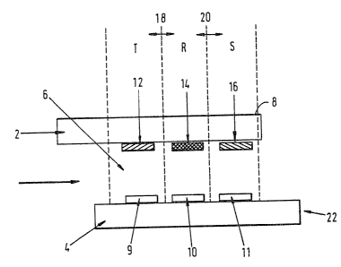
Referring to Fig. 1, the device depicted comprises
an upper plate 2 fashioned of transparent material (e. g.
of plastic material, quartz, silica or glass) carrying
on its external face an opaque coating 8, and a lower
plate 4 fashioned of transparent material, both plates
being around 1 mm thick and fixed together in
substantially parallel relationship, less than 1 mm
apart by means of bonding tracks 38 (see Fig. 2) of
suitable adhesive. In the embodiment shown, the cell
cavity 6 so formed is open to the surroundings at both
ends, so that when liquid sample is drawn into one
opening of the cavity by means of capillarity, air may
escape through the other opening. In the embodiment
shown, the two plates are offset, although this is not a
necessary feature.
Carried on the inner surface of the upper plate 2
are three patches of reagents appropriate to the test
being carried out, being carried by zone I (12), zone II
(14) and zone III (16) as defined hereinbefore. These
reagents are contained within the device in a soluble
releasable form (reagents X, Y and Z respectively)
Carried on the inner surface of the lower plate 4
are three patches of reagent appropriate to the test
WO 92/09892 ~ ~ ~ ~ ~ 4 ~ PCT/GB91/02058
being carried out, being carried by zone IV (9), zone V
(10) and zone VI (11) as defined hereinbefore, said
zones 9, 10 and 11 being directly below the zones 12, 14
and 16 respectively on the plate 2. In the case of an
5 immunoassay, the zones 9, 10 and 11 will each carry, for
example, a relevant immobilised antibody or antigen or
hapten. These are reagents A, B and C.
The operation in use of several embodiments of the
device shown in Fig. 1 will now be described. Although
10 the following descriptions relate to the use of a device
in a labelled-antigen format competition-type
immunoassay, it should be understood that devices
according to the invention are also suitable for use in
labelled-antibody format immunoassays (both competition-
15 type and sandwich-type) and in other types of assay
(direct, sandwich-type or competition-type) or in other
types of chemical or biochemical tests.
The sample liquid passes into the device in the
direction of the arrow shown in Fig. 1. A short time
20 after the cavity 6 fills with sample liquid, the patches
12, 14, 16 of material dissolve, releasing the
respective reagents into the liquid.
The success of the method of assay of the present
invention depends on the spatial separation (i.e. non
25 mixing) of the reagents released into the sample
solution from the patches 12, 14, 16. As mentioned
hereinbefore, the patches 12, 14, 16 may be carried on
the upper plate 2 by means of suitable dissoluble
material(s). Suitable dissoluble materials include
30 humectant coatings, e.g. sucrose- or sorbitol-based. In
the embodiment shown in Fig. 1, the patches 12, 14, 16
are separated from each other. The length of the plates
2, 4 is about 15 mm, the smallest dimension of the
cavity 6 is less than 1 mm (typically about 0.1 mm) and
35 the lateral separations 18, 20 between the patches are
typically 2-3 mm. The arrangement of the device is such
that when filled with sample liquid, lateral mixing of
reagents is very slow (typically 2 or 3 hours), whereas
WO 92/09892 ~ ~ .' ~ (! '; PCT/GB91/02058
~~.:~:v..
36
vertical mixing across the narrow capillary gap is rapid
(several seconds only). Thus, mixing of reagents from
the three patches is not a problem subsequent to the
device being filled, since most tests (including
immunoassays) reach equilibrium in less than 2 hours.
The possibility of lateral mixing occurring is greatest
during the filling of the device, when "washdown" of
reagents may occur in the direction of flow of the
sample liquid into the device. A further optional
precaution against such washdown occurring is to coat
the patches 12, 14, 16 with a thin layer of a material
which provides some delayed release of the reagents
within the patches. Suitable materials for coating the
patches include, for example, polyvinyl alcohol (PVA).
A suitable PVA coating would take typically 2-10 seconds
to dissolve after initial contact of a sample liquid.
In an alternative embodiment to that shown in Figure 1,
the patches 12, 14 and 16, and thereby the corresponding
patches 9, 10 and 11, may be abutted. There will, in
this case, be lateral mixing at the interface of the
reagent patches. However, the portion of each of the
zones which is subsequently selected for the purpose of
measurement, as described hereinafter, is chosen so that
no mixing will occur between the said portions of
adjacent zones.
In one embodiment of the device of the type shown
in Fig. 1 which is set up for a competition-type
immunoassay for an antigen (which embodiment corresponds
to the first competition-assay embodiment of the device
hereinbefore described), patch 12 may contain a
fluorescently labelled antigen analogue together with an
amount of a specific antibody to the antigen under
assay. Patch 9 would then comprise an immobilised
specific binding partner being a specific antibody to
the specific antibody to the antigen under assay.
Thus, upon introduction of the sample liquid, the patch
12 dissolves, releasing antigen analogue and specific
WO 92/09892 ~ ~ ~ ~ ~ ~ ~ PCT/GB91/02058
37
antibody to the antigen under assay into the sample
liquid. These reagents released from patch 12 should
preferably remain substantially within the region
indicted in Fig. 1 by the label "T". In general, this
will be the case when lateral diffusion is slow.
Antigen introduced in the sample liquid competes with
antigen analogue for epitopic binding sites on the
specific antibody to the antigen which, either before or
after such competition occurs, becomes bound to the
epitopic binding sites on the layer of specific antibody
contained in patch 9. The amount of fluorescent
material which becomes indirectly bound to the
immobilised specific antibody in patch 9 will therefore
be a function of the concentration of antigen in the
sample liquid. Conventional competition-type optical
immunoassays involve this type of competitive
equilibrium. Thus region T acts as the "measurement
region". When patch 14 dissolves, a known quantity of
fluorescently labelled antigen analogue in a fully
saturated complex with its specific antibody is released
into the sample liquid which is present in the region R
as shown in Fig. 1. Thus, by comparison with region T,
the antigen analogue: specific antibody complex becomes
bound to the immobilised specific antibody contained in
patch 10 (which will be identical to that in patch 9).
Thus, initially, a maximum amount of fluorescent
material is indirectly bound to the immobilised antibody
in patch 10. Thus, the calibration region R acts as a
"high signal calibration region". After a significant
time period e.g. 1 to 2 hours, the antigen analogue
bound to the immobilised antibody will compete with the
antigen from the sample liquid. This competition will
result in a slow decrease in the amount of fluorescent
material indirectly bound to the immobilised antibody in
patch 11, until the competition has reached equilibrium.
When patch 16 dissolves, a known quantity of the antigen
under assay in a fully saturated complex with its
WO 92/09892 PCT/GB91/02058
X095245
3s
specific antibody is released into the sample liquid
present in region S as shown in Fig. 1. Thus, in an
analogous manner to region R, the antigen: specific
antibody complex becomes bound to the immobilised
specific antibcdy contained in patch 11 (which will be
identical to that in patches 9 and 10). Thus, initially
and subsequently, no fluorescent material becomes
indirectly bound to the immobilised antibody in patch
11. Thus the calibration region S acts as a "zero
signal calibration region".
For this first embodiment, the three regions T, R
and S and the reagents contained therein are illustrated
diagrammatically in Figure 3a.
The subsequent descriptions of examples of the
device according to the present invention are set out in
terms of the three regions T, R and S as defined above.
One may use any of the regions T described herein
together with one of the regions R described herein (in
which if a binding reaction occurs at the surface 4 in
this region R it is analogous to that which occurs at
the surface 4 in the region T) and optionally one or
more further regions selected from any of regions R and
S described herein.
In a second example of the device for a
competition-type assay, the specific antibody to the
antigen under assay may be contained within patch 9. In
a third example, the specific antibody to the antigen
under assay may be prebound to the immobilised antibody
contained in patch 9. In a fourth example, the specific
antibody to the antigen under assay may itself be
immobilised on the surface containing patch 9. In each
of these three examples, the resulting competition will
be analogous to that in the measurement region described
above, and in these examples are thereby described
further measurement regions.
The region T for these three examples are
illustrated diagrammatically in Figures 3b, 3c and 3d
WO 92/09892 PCT/GB91/02058
~~~~~45
respectively.
In a fifth example the device for a competition-
type assay, when patch 14 dissolves, a known quantity of
fluorescently-labelled antigen analogue together with a
known quantity of the antigen under assay are released
into the sample liquid which is present in region R as
shown in Fig. 1. In general, the quantities of antigen
analogue in patches 12 and 14 will be the same, although
this is not a necessary condition for successful
operation of the device. Thus, by comparison with
region T, antigen analogue competes with an augmented
amount of antigen, for example sample antigen and
antigen already in the device, for binding sites on the
specific antibody which is contained in patch 10. This
specific antibody is a specific antibody to the antigen
under assay and is present in a saturated complex with
an immobilised specific antibody contained in patch 10.
The amount of fluorescent material which becomes
indirectly bound to the immobilised specific antibody in
patch 10 will therefore be a function of the
concentration of the total amount of antigen in the
region R of the sample liquid. Thus calibration region
R acts as a "positive calibration region". In a sixth
example, the specific antibody to the antigen under
assay may itself be immobilised onto the region 10. In
a seventh example, the specific antibody to the antigen
under assay may be present in a fully saturated complex
with both the antigen analogue and the antigen 14, the
immobilised specific antibody contained in patch 10
being a specific antibody to the specific antibody to
the antigen under assay. Both these examples result in
an analogous positive calibration region.
The region R for these three examples is
illustrated diagrammatically in Figures 3e, 3f and 3g
respectively.
In an eighth example of the device for a
competition-type assay, patch 14 may contain no reagent.
WO 92/09892 PCT/GB91/02058
'~~95245
The specific antibody to the antigen under assay is
contained within patch 10 together with an equivalent
amount of fluorescently labelled antigen analogue (the
same reagent as in patch 12) and together with an
5 equivalent amount of an immobilised specific antibody
which is a specific antibody to the specific antibody to
the antigen under assay. In a ninth example the
specific antibody to the antigen under assay may be
prebound in a complex to the immobilised specific
10 antibody in patch 10. In a tenth example, the antigen
analogue and specific antibody to the antigen under
assay may both be prebound in a complex to the
immobilised specific antibody in patch 10. In an
eleventh example, the specific antibody to the antigen
15 under assay may itself be the immobilised antibody in
patch 10 together with the antigen analogue preferably
in a fully saturated complex. In each of these four
examples, initially a maximum amount of fluorescent
material becomes bound to the immobilised antibody in
20 patch 10. Thus in these examples, region R acts as a
high signal calibration region. After a significant
time period e.g. 1 to 2 hours, the antigen analogue
bound to the immobilised antibody will compete with the
antigen from the sample liquid. This competition will
25 result in a slow decrease in the amount of fluorescent
material indirectly bound to the immobilised antibody in
patch 11, until the competition has reached equilibrium.
The region R for these four examples is illustrated
diagrammatically in Figs. 3h, 3i, 3j and 3k
30 respectively.
In a twelfth example of the device for a
competition-type assay, when patch 16 dissolves
fluorescently-labelled antigen analogue is released into
the sample liquid present in region S as shown in Fig.
35 1. The specific antibody to the antigen under assay is
contained within patch 11 together with an equivalent
amount of the antigen under assay and together with an
WO 92/09892 ~ ~ ~, ~ PCT/GB91/02058
41
equivalent amount of an immobilised specific antibody
which is a specific antibody to the specific antibody to
the antigen under assay. In a thirteenth example the
specific antibody to the antigen under assay may be
prebound in a complex to the immobilised specific
antibody in patch 10. In a fourteenth example, the
antigen under assay and specific antibody to the antigen
under assay may both be prebound in a complex to the
immobilised specific antibody in patch 10. In a
fifteenth example, the specific antibody to the antigen
under assay may itself be the immobilised antibody in
patch 10 together caith the antigen under assay
preferably in a preformed complex. In each of these
four examples, initially no fluorescent material will
become bound to the immobilised antibody in patch 11.
Thus in these four examples, region S acts as a zero
signal calibration region. After a significant time
period, e.g. 1 to 2 hours, the antigen bound to the
immobilised antibody will become displaced by the
fluorescent antigen analogue released from patch 16
resulting in a competition between the antigen and the
antigen analogue. This competition process can be
followed by the amount of fluorescent material that
becomes bound to the immobilised specific antibody in
patch 11.
The region S for these four examples is illustrated
diagrammatically in Figs. 31, 3m, 3n and 3p
respectively.
In a sixteenth and seventeenth example of the
device for a competition-type assay, when patch 14
dissolves, a fluorescently labelled specific antibody,
being either a specific antibody for the antigen under
assay or being an antibody non-specific for the antigen
under assay, is released into the sample liquid present
in region R as shown in Fig. 1. The immobilised
antibody which is contained within patch 10 will be a
specific antibody to the fluorescently labelled antibody
WO 92/09892 PCT/GB91/02058
42
contained in patch 14. Thus a maximum amount of
fluorescent material becomes bound to the immobilised
antibody in patch 10. Thus region R acts as a high
signal calibration region.
The region R for these examples are illustrated
diagrammatically in Figs. 3q and 3r respectively.
In an eighteenth example of the device suitable for
a competition-type assay, no reagent is contained in
patch 14. The immobilised antibody which is contained
within patch 10 will be a fluorescently-labelled
specific antibody either for the antigen under assay or
for an antigen not being the antigen under assay. In
either case, no further fluorescent material will become
bound to the immobilised antibody in patch 10. The
presence of the fluorescent label on the immobilised
antibody will mean that region R will act as a high
signal calibration region.
The region R for this embodiment is illustrated
diagrammatically in Fig. 3s.
In a nineteenth example of the device suitable for
a competition-type assay, when patch 16 dissolves,
fluorescently labelled antigen analogue (the same
reagent as in patch 12) is released into the sample
liquid present in region S as shown in Fig. 1. In
general, the quantity of antigen analogue in patch 16
will be the same as the quantity in patch 12, although
this is not a necessary condition for successful
operation of the device. The immobilised antibody which
is contained within patch 11 will be a binding partner
non-specific for the antigen in the sample liquid.
Thus, no fluorescent material will become bound to the
immobilised antibody in patch 11. Thus, region S acts
as a zero signal calibration region.
The region S for this embodiment is illustrated
diagrammatically in Fig. 3t.
In a twentieth example of the device for a
competition-type assay, when patch 16 dissolves, a
WO 92/09892 PCT/GB91/02058
~0~~245
43
fluorescently labelled antigen analogue, the antigen
being distinct from the antigen under assay, is released
into the sample liquid present in region S as shown in
Fig. 1. The antibody which is contained within patch 11
will be a specific binding partner for the antigen under
assay. Thus, no fluorescent material will become bound
to the immobilised antibody in patch 11. Thus, region S
acts as a zero signal calibration region.
The region S for this embodiment is illustrated
l0 diagrammatically in Fig. 3u.
In a twenty-first example of the device for a
competition-type assay, when patch 14 dissolves,
fluorescently labelled antigen analogue (the same
reagent as in patch 12) is released into the sample
liquid present in region R as shown in Fig. 1. The
antibody which is contained within patch 10 will be a
binding partner non-specific for the antigen in the
sample liquid together with an amount of a fluorescently
labelled analogue of the antigen which is a specific
binding partner for the antibody in patch 10 in a
complex, which has preferably been preformed in the
patch 10. Thus, a maximum amount of fluorescent
material becomes bound to the immobilised antibody in
patch 10. Thus, region R acts as a high signal
calibration region.
The region R for this embodiment is illustrated
diagrammatically in Figure 3v.
Further examples of embodiments of the device for a
competition-type assay are illustrated in Figs. 4a to
4t. Figs. 4a to 4c illustrate examples of the
measurement region T. Figs. 4d and 4e illustrate
examples of a positive calibration region R. Figs. 4f
to 4m illustrate examples of a high signal calibration
region R. Figs. 4n to 4r illustrate examples of a zero
signal calibration region S. With the exception of
Figs. 4g, 4h, and 4r, these examples include the use of
labelled-antibody. Figures 4a, 4e, 4f, 4h, 4k and 41
WO 92/09892
PCT/G B91 /02058
, c~ ,t
44
illustrate the use of a species such as, for example,
poly-L-lysine, bovine serum albumin or keyhole limpet
haemocyanin, to facilitate immobilisation of the antigen
in the relevant patch. Figure 4b illustrates an
alternative use of a species such as, for example,
avidin to facilitate the antigen-antibody binding
reaction.
For the direct assay embodiments of the device
hereinbefore described, the example of the measurement
region T is illustrated in Fig. 5n. Examples of a
positive calibration region R are illustrated in Figs.
5p and 5q. Examples of a high signal calibration region
R are illustrated in Figs. 5r to 5t. The calibration
region S is illustrated in Fig. 5u, being a zero signal
calibration region.
For the sandwich assay embodiments of the device
hereinbefore described, an example of the measurement
region T is illustrated in Fig. 5a. An example of a
positive calibration region R is illustrated in Fig. 5b.
Six examples of a high signal calibration region R are
illustrated in Figs. 5c to 5h. Two examples of a zero
signal calibration region S are illustrated in Figs. 5i
and 5j.
Certain examples of calibration regions described
for use in a competition-type assay may find use in a
sandwich assay embodiment of the device and vice versa.
Figs. 5c and 5g illustrate two such examples used in
both competition-type and sandwich-type assays.
In all of the examples hereinbefore described, the
same fluorescent species is used as a fluorescent label
on those reagents stated to be labelled.
In the embodiment of the device shown in Figure 1,
the patch 12 (being zone I as defined hereinbefore) is
the closest of the three patches on plate 2 to the end
of the device where introduction of the sample liquid
occurs, whilst the patch 16 (being zone III) is the
furthest of the three patches on plate 2 from said end
WO 92/09892 ~Q 4 ~ PCT/GB91/02058
of the device. In alternative embodiments of the
device, the patches 12, 14 and 16 and thereby the
corresponding patches 9, 10 and 11 may be arranged in
any order from the end of the device where introduction
5 of the sample liquid occurs.
In the various embodiments of the device according
to the invention as defined hereinbefore, one pair of
zones provides the measurement region whereas the other
two pairs of zones provide calibration regions, such
l0 calibration regions being selected from a positive
calibration region, a zero signal calibration region or
a high-signal calibration region.
In several of the embodiments of the device as
defined hereinbefore, in order to give the desired
15 signal, consideration must be given to the kinetic
characteristics of the various binding reactions
involved. The reagents are chosen and the signals from
the various regions read at the appropriate time to
achieve the desired signal. For certain formats it is
20 important to ensure that the binding of the intended
species occurs and no dissociation occurs in any complex
initially formed prior to the reading of the signal.
Further embodiments of the device with only one
calibration region or with three or more calibration
25 regions suggest themselves and are included within the
scope of the present invention, the calibration regions
being preferably selected from those described
hereinbefore or those described hereinafter in the
Examples.
30 Assay measurements are obtained by illuminating in
turn with light of an appropriate frequency or range of
frequencies the portions of the immobilised layer (or a
part only of said portion) which lies in region T,
region R and region S. This light leads to excitation
35 of fluorophores within the region of illumination.
These fluorophores then fluoresce, emitting light some
of which passes into the second date 4 and is guided by
WO 92/09892 ~~ ~ ~ ~ ~ ~ ~ PCT/GB91/02058
46
said plate to emerge from the smooth edge 22 with
characteristics as described in EP-A-171148, which light
may then be filtered and analyzed as desired.
Sequential illumination of the different zones 9,
10 and 11 may be effected by a shuttering mechanism in
the illumination optics, details of which will be
apparent to one skilled in the art. The optical signals
arising from fluorescent species in each zone will all
emerge in turn from the optical edge 22 and be detected
by the same optical detector before being processed in a
desired manner. Alternatively illumination of the
different regions of the immobilised layer 10 may be
effected by use of a number of identical light sources.
Alternatively, it is possible to use a single light
source and index the device past the light source
thereby sequentially illuminating the different regions
of the immobilised layer 10.
Although the preceding discussion is made with
particular reference to fluorescent labels, it will be
appreciated that it also applies to reagents conjugated
to labels which exhibit other properties (e. g.
phosphorescence or luminescence).
Fig. 2 shows a plan view of the lower plate of the
device shown in Fig. 1. The patches of material 32, 34,
36 correspond to those labelled 12, 14, 16 respectively
in Fig. 1. Also shown in Fig. 2 are the bonding tracks
38 which cause mutual adhesion of the upper and lower
plates of the device. The depth of the capillary gap
may be defined by incorporating glass ballotini of
appropriate diameter (for example, about 100 microns) in
the glue which is used for the bonding tracks 38.
The method of the invention is particularly
applicable to assays of antigens or antibodies, i.e. to
immunoassays, and in a preferred embodiment of the
invention the ligand is an antigen and the specific
binding partner comprises an antibody to the said
antigen. However, the invention is not to be taken as
limited to assays of antibodies or antigens. Examples
WO 92/09892 PCT/GB91/02058
209524
47
of ligands which may be assayed by the method of the
invention are given in Table 1 below, together with an
indication of a suitable specific binding partner in
each instance.
Table 1
Ligand Specific Binding Partner
antigen specific antibody
antibody antigen
hormone hormone receptor
hormone receptor hormone
polynucleotide strand complementary
polynucleotide strand
avidin biotin
biotin avidin
protein A immunoglobulin
immunoglobulin protein A
enzyme enzyme cofactor
(substrate) or inhibitor
enzyme cofactor enzyme
(substrate) or inhibitor
i
lectins specific carbohydrate
specific carbohydrate lectins
of lectins
The method of the invention has very broad
applicability but in particular may be used to assay:
hormones, including peptide hormones (e. g. thyroid
stimulating hormone (TSH), luteinizing hormone (LH),
human chorionic gonadotrophin (hCG), follicle
stimulating hormone (FSH), insulin and prolactin) or
non-peptide hormones (e.g. steroid hormones such as
cortisol, estradiol, progesterone and testosterone, or
thyroid hormones such as thyroxine (T4) and
triiodothyronine), proteins (e. g. carcinoembryonic
antigen (CEA) and antibodies and alphafetoprotein
WO 92/09892 ~ r~ ~ ~~~ ~ PCT/G B91 /02058
48
(AFP)), drugs (e. g. digoxin, drugs of abuse), sugars,
toxins, vitamins, viruses such as influenza, para-
influenza, adeno-, hepatitis, respiratory and AIDS
viruses, virus-like particles or microorganisms.
It will be understood that the term "antibody" used
herein includes within its scope:
(a) any of the various classes or sub-classes of
immunoglobulin, e.g. IgG, IgA, IgM, or IgE derived
from any of the animals conventionally used, e.g.
sheep, rabbits, goats or mice,
(b) monoclonal antibodies,
(c) intact molecules or "fragments" of antibodies,
monoclonal or polyclonal, the fragments being those
which contain the binding region of the antibody,
i.e. fragments devoid of the Fc portion (e. g. Fab,
Fab', F(ab')z), the so-called "half-molecule"
fragments obtained by reductive cleavage of the
disulphide bonds connecting the heavy chain
components in the intact antibody or fragments
obtained by synthetic methods.
The method of preparation of fragments of
antibodies is well known in the art and will not be
described herein.
The term "antigen" as used herein will be
understood to include both permanently antigenic species
(for example, proteins, bacteria, bacterial fragments,
cells, cell fragments and viruses) and haptens which may
be rendered antigenic under suitable conditions.
Examples of fluorophores which may be used in the
method of assay according to the invention include
fluorescein and its derivatives (e. g. fluorescein
isothiocyanate (FITC)), rhodamine and its derivatives
(e. g. XRITC, TRAP, TRITC), Lucifer yellow, 2,4-
dinitrofluoro-benzene, phenylisothiocyanate, dansyl
chloride, phycobiliproteins (e.g. allophycocyanin and
phycoerythrin) and indocyanins.
The present invention further provides apparatus
WO 92/09892 PCT/GB91/02058
49
suitable for use in the method of assay according to the
invention as hereinbefore described which comprises a
fluorescence capillary fill device according to the
invention as hereinbefore defined; a source of radiation
capable of being arranged such that, in use, radiation
enters the said device such that fluorophores are
excited; and means for monitoring the emerging
radiation. In a further embodiment, the device can be
illuminated via a mask, thereby defining the effective
volume of the device in which the binding reaction
occurs. The effective volume is the product of the
distance between base and top plates of the device and
the area of the illumination zone as defined by the mask
55 in the optical train.
The present invention further provides a kit for
performing a method of assay according to the present
invention comprising a device as hereinbefore defined
together with appropriate ancillary reagents.
In a quantitative competition assay, it is
necessary to have an accurate measurement of the
concentration of a particular analyte in a sample.
Various factors may alter the level of the observed
signal in the assay and it is therefore essential to
have a sufficient number of defined signals relating to
particular concentrations of analyte to enable a
standard assay curve to be constructed. Thus, by using
a variety of calibration regions wherein the initial
binding of fluorophore to the calibration surface can be
pre-determined by using a known amount of reagents as
described in the embodiments hereinbefore, such defined
signals can be achieved which will also compensate for
the various factors outlined above. In general, known
assay techniques employ a 4 or 5 point calibration
procedure and so for a quantitative assay, it is
preferable to have more than three calibration regions
and most preferably five or greater.
In a qualitative or semi-quantitative competition
WO 92/09892 PCT/GB91/02058
~a9524~5
assay, it is only necessary to determine whether a
sample has more or less than a certain concentration of
a particular analyte, this concentration being called
the 'cutoff level' for the particular assay. Therefore,
5 by relating the measured amount of the analyte in a
sample to this 'cutoff level', one can determine whether
the sample is 'positive' or 'negative'. Such a 'cutoff
level' is generally chosen as the point referring to a
500 level of binding to the measurement surface of the
l0 species giving rise to the signal although other points
may be chosen as the cut-off level.
Similar considerations apply to sandwich assays.
In such assays, however, due to the fact that the amount
of fluorophore binding to the measurement surface is
15 directly proportional to the amount of sample analyte, a
straight-line standard assay graph needs to be
constructed. This is easier to achieve than the
construction of a standard assay cure for a competion
assay. In general, therefore, a quantitative assay
20 requires only a 3-point calibration procedure; therefore
it is preferable to have 2 calibration regions, more
preferably 3 in a sandwich-type assay.
In the various embodiments described hereinbefore
for either a competition or sandwich assay, the "high
25 signal calibration regions" have been particularly
designed so that an initial maximum amount of
fluorescent material becomes bound to the surface.
However, by altering the amounts of the various reagents
concerned, different amounts of fluorescent material may
30 initially become bound resulting in other non-zero
signals arising from these regions, such amounts being
chosen to give signals corresponding to the 'cutoff
level' required. Examples include those illustrated in
Figs. 3g, 3w, 3s, 3v, 3h, 3i, 3j, 3~:, 3x, 4g, 4h, 4k,
35 41, 4t, 5c, 5e, 5f, 5g and 5h.
The "positive calibration regions" as previously
described for a competition-type assay are preferably
WO 92/09892 PCT/GB91/02058
~~95245
51
designed so that the signal relates to a 'cutoff value'
corresponding to the inflection point of the standard
assay curve.
The zero signal calibration regions as previously
described give a signal corresponding to the background
signal for the assay device. For a competition assay,
the regions are designed such that the signal obtained
corresponds to the low asymptote of the standard assay
curve, whereas for a sandwich assay, the regions are
designed such that the signal corresponds to the lower
limit of the standard assay graph.
The following Examples serve to illustrate
embodiments of the present invention without, however,
limiting it.
Examples 1 to 8 illustrate embodiments of the
invention in which an antigen-labelled format for a
competitive assay of an antigen is described.
WO 92/09892 ~ ~ ,~ ~ ~ ~ ~ PCT/GB91/02058
52
EXAMPLE 1
1. PREPARATION OF STARTING MATERIALS
1.1 Fabrication of Antibody-coated Waveguides
A sheet of Permabloc class (Pilkington Glass
Ltd., St. Helens, UK) having a thickness of
about 1 mm was cleaned with detergent (e. g.
Tween 20) in ultra-pure water with ultrasonic
agitation. The surface of the glass was
activated by incubating it in a 2o solution
of aminopropyltriethoxysilane in water at a
pH of 3 to 4 for two hours at 75°C. After
rinsing in water, the glass sheet was dried
at 115°C for at least four hours. The glass
was then incubated for 60 minutes in a 2.5%
solution of glutaraldehyde in a 0.05M
phosphate buffer (pH 7), and then washed
thoroughly with distilled water. The glass
was incubated for two to four hours in a 1
percent solution of a rat anti-mouse
monoclonal antibody in phosphate buffer (pH
7). The glass sheet was then washed with
buffer solution. Unwanted adsorbed protein
was removed by soaking with a 6M urea
solution in known manner. This formed plate
4 of the FCFD test device as illustrated in
Figure I.
1.2 Preparation of Morphine Conjugated to
Fluorescein Isothiocyanate (FITC)
200 mg of FITC (Sigma Chemical Company Ltd.,
UK) and 5 mg of morphine-3-glucuronide were
mixed together in 1.4 ml of 0.2 M sodium
bicarbonate buffer solution (pH Sa.O). The
WO 92/09892 PCT/GB91/02058
~~~5245
53
mixture was left for 18 hours at room
temperature, during which conjugation of FITC
to the morphine occurred. The mixture was
then purified by gel filtration on Sephadex
G-50 superfine.
1.3 Microdosing of the Specific Reagents Over
Each Discrete Reference Zone
l0 An opaque coating was screen printed onto a
clean sheet of Permabloc glass as described
in WO-90/14590. The measurement zone (zone
I) was fabricated by microdosing a layer of
morphine-FITC conjugate followed by a
separate layer of mouse anti-morphine
monoclonal antibody in an area 3 x 7 mm onto
the glass over zone I. Each layer was
allowed to air dry before a second reagent
layer was added on top of it. Since the
layers are fabricated in discrete stages,
there is no preferential binding of the
morphine FITC to the anti-morphine monoclonal
antibody when the patient sample is
introduced at the time of assay.
In this Example zone II was fabricated to
produce a signal equivalent to the high
asymptote of the standard curve from the
measurement zone by using a premix of the
mouse anti-morphine monoclonal antibody and
morphine-FITC conjugate accurately microdosed
over the zone II area.
Zone III was fabricated to produce a signal
equivalent to the low asymptote of the assay
as defined by the measurement standard curve
by using a premix of mouse anti-morphine
WO 92/09892 PCT/GB91/02058
54
monoclonal antibody and morphine accurately
microdosed over the zone III area.
This glass sheet containing zones I, II and
III forms the plate 2 of the FCFD test device
as illustrated in Figure 1.
1.4 Fabrication of FCFD Test Devices
Test devices such as have been described in
EP-A-0171148 were fabricated by screen
printing onto the waveguide resulting from
step 1.1 above bonding tracks of an
ultraviolet curing glue (UVS 91, Norland
Inc., USA) containing glass microspheres of
diameter 100 microns (Jencons Ltd., UK) in a
pattern defining the long edges of the
capillary cell devices (see Figure 2). A
sheet of glass as defined in 1.3 above was
then placed over the waveguide, and a vacuum
applied to the laminate. As result of the
vacuum, the upper sheet of glass was caused
to press down onto the glue, the glass
microspheres defining a gap of 100 microns
between the glass sheets. The laminate was
then exposed to an ultraviolet light source
to cure the glue. Finally, the laminate
sheet was broken into individual test devices
as described in EP-A-0171148.
1.5 Preparation of Morphine Standard Solutions
A freeze-dried preparation of morphine-3-
glucuronide was obtained from Sigma Chemical
Company Ltd. This sample was diluted in
pooled human urine buffered to pH 7.5, to
give the range of morphine standards
WO 92/09892 ~ ~ ~ ~ ~ ~ ~ PCT/GB91/02058
required.
1.6 Apparatus Used in the Measurement of the
Morphine Assay
5
Figure 6 shows a simple fluorimetry apparatus
which was used to make suitable assay
measurements as described in GB8911462.3.
Light from a zenon flash lamp 51 (Heinmann)
10 is roughly collimated by a lens 52 before
passing through a filter stack 53 which
defines the wavelength range used to excite
the FITC-labelled antibodies. The filter
stack comprises three filters: a BG7 Schott
15 glass filter (Ealing Electro Optics UK Ltd.,
Watford, UK) a 450-480 nm FITC bandpass
interference filter (Optometrics Ltd., UK)
and a 474 nm shortpass interference filter
(Comar Instruments Ltd., Cambridge, UK). A
20 second lens 54 focused the excitation light
onto the active surface of the test cell 56
through an aperture 55 which defines the
illuminated area and hence the active volume
of the test cell.
Light emitted from the optical edge 63 of the
test cell passes through an aperture 57 which
prevents light emitted directly out of the
solution from entering the detection optics.
A lens system 58 collects the emitted light
and an aperture 59 defines the angular range
over which the emission is measured. This
was chosen to coincide with angles associated
with evanescently coupled fluorescence
emission. A Schott OG515 515 nm colloidal
glass longpass filter GO (Ealing Electro
WO 92/09892 , PCT/GB91/02058
56
Optics UK Ltd., Watford, UK) filters out any
scattered pump light and a second lens
focuses the emission onto a photomultiplier
detector (Hamamatsu R931A, Hakuto UK Ltd).
2. ASSAY PROCEDURE FOR MORPHINE
Eight test CFDs were chosen to produce a standard
curve and each was filled with a different morphine
standard solution. The CFDs were read after an
incubation in a humid environment. Zones V and VI
were read after 3 minutes of incubation, so that the
measured signal could be considered to represent the
high and low asymptote respectively for the assay -
(ie, before significant dissociation had occurred).
Figure 7 shows a plot of signal versus time for zone
V. It is apparent from this that between 0 and 200
seconds the signal is independent of the analyte
concentration, whereas after 200 seconds the labelled
reagent begins to dissociate from the base plate and
competition between the labelled ligand analogue and
the ligand occurs so that the signal becomes dependent
upon the analyte concentration. Hence this zone (and
also zone VI) must be read before 200 seconds have
elapsed. Zone IV was read after a 15 minute
incubation (after the assay had reached equilibrium).
From this zone the standard curve was generated
(Figure 8). [It will be appreciated that the time
before cahich the reference zone must be read (200
seconds in this particular example) will be dependent
on the particular assay system and reagents used].
Figure 8 shows that the signal from zone IV can be
used to derive the analyte concentration in the
patient sample. Zones V and ~~I produce a signal which
can be used to fix the assay high and low asymptote
respectively. At the read tire chosen, the signals
produced from zones V and VI are independent of
analyte concentration.
Thus the signal prom zone I~' can be compensated for
WO 92/09892 ~ ~ (~ 4 ~C PCT/GB91/02058
57
any change in background fluorescence or assay range by
using the measured values from zones V and VI, and
comparing them to reference data for zones V and VI
obtained during device fabrication.
EXAMPLE 2
1. PREPARATION OF STARTING MATERIALS
1.1 Fabrication of Antibody-coated Waveguides
As for example 1, with the exception that
zones V and IV were treated with a premixed
solution of rat anti-mouse and mouse anti-
morphine antibodies. Zone VI was not used in
this example.
1.2 Preparation of Morphine Conjugated to
Fluorescein Isothiocyanate (FITC)
As for example 1.
1.3 Microdosing of the Specific Reagents Over
Each Discrete Reference Zone
As for example 1, except that zone II has a
layer of morphine FITC conjugate and
unlabelled morphine (either as a premixed
solution or as separate layers) microdosed on
to the glass. Zone III is microdosed with
morphine FITC conjugate.
1.4 Fabrication of FCFD Test Devices
As for example 1.
i.5 Preparation of Morphine Standard Solutions
WO 92/09892 PCT/GB91/02~58
~~~~~4~
58
As for example 1.
1.6 Apparatus Used in the Measurement of the
Morphine Assay
As for example 1.
2. ASSAY PROCEDURE FOR MORPHINE
The CFDs were filled with a range of morphine
standards and read after an incubation in a humid
environment.
Zones IV and V were read when the assay had come to
equilibrium - i.e. fifteen minutes. (Figure 9).
Zone IV is the assay measurement zone. Zone V
shows an offset when compared to zone IV at low
analyte concentrations. This zone is used to
define the assay cutoff. Thus when zone IV is x
units larger than zone V, the patient sample is
considered to be negative in a competition assay.
Furthermore, when the sample from zone IV is y
units less than zone V, the patient sample is
considered to be positive. It is anticipated that
zones VI and III would be used to complete the
calibration regions, by treating the plate carrying
zone VI with rat anti-mouse antibody and the plate
carrying zone III with a combined complex of mouse
anti-morphine antibody with morphine FITC
conjugate.
Zone VI c:~ould be read after 3 minutes of incubation
so that the measured signal could be considered to
represent the high asymptote of the assay and is
independent of the morphine concentration of the
patient sample. Thus zone V would be used to
define the cutoff position and zone VI to confirm
WO 92/09892 ~ ~ ~ ~ ~ ~ PCT/G B91 /02058
59
that the reagents were working, regardless of
patient sample concentration.
EXAMPLE 3
1. PREPARATION OF STARTING MATERIALS
1.1 Fabrication of Antibody-coated waveguides.
As for example l, except that zones IV and V
were treated with a premixed solution of rat
anti-mouse and mouse anti-morphine
antibodies. Zone VI was not used in this
example.
1.2 Preparation of morphine conjugated to
fluorescein isothiocyanate (FITC).
As for example 1.
1.3 Microdosing of the Specific Reagents Over
Each Discrete Reference Zone
As for example 1 except that zone II has a
layer of morphine-FITC conjugate and
unlabelled morphine (either as a premixed
solution or as separate layers) microdosed
onto the glass and zone I is microdosed with
morphine FITC conjugate. Zone III is not
used in this Example.
1.4 Fabrication of FCFD Test Devices
As for example 1.
1.5 Preparation of Morphine Standard Solutions
WO 92/09892 PCT/GB91/02058
As for example 1.
1.6 Preparation of Morphine Standard Solutions
Using Adulterated Urine:-
5
Urine samples were obtained from volunteers
known not to be taking morphine and, after
pooling, the samples were treated as
follows:-
a) The pH of the urine increased to pH 10
by the addition of sodium hydroxide.
b) The pH of the urine decreased to pH 4.5
by the addition of hydrochloric acid.
c) The pH of the urine decreased to pH 4.0
by the addition of hydrochloric acid.
d) The fluorescence of the urine increased
by the addition of TRAP to give a final
concentration of 1 um/L.
e) The fluorescence of the urine increased
by the addition of TRAP to give a final
concentration of 6 um/L.
Morphine standard solutions were then made up
using these 5 types of urine as in example 1,
giving a range of morphine concentrations
above and below the assay cut-off.
1.7 Apparatus used in the measurement of the
morphine assay
As for example 1.
WO 92/09892 ~ ~ ~ PCT/GB91/02058
61
2. ASSAY PROCEDURE FOR MORPHINE
Assay curves were generated using eight standards
in triplicate using unadulterated urine. Samples
made up from the adulterated urines were assayed
and their the signals obtained from the values read
off the standard curve. The signals obtained from
the measurement and reference zones were used for
each type of sample using the procedure described
l0 in example 2.
Figures 10a and lOb show plots of the number of
positive results against dose for various urine
types using firstly the standard assay method
(Fig.lOa) and then the positive control reference
format (10b). Ideally the step change between
positive and negative samples should be abrupt but
with the standard assay method, this step change
varies with sample type. Use of the reference zone
results in the curves being much more tightly
grouped.
EXAMPLE 4
1. PREPARATION OF STARTING MATERIALS
1.1 Fabrication of Antibody-coated Waveguides
As for example 1, with the exception that
zone V was treated with a mouse monoclonal
antibody (against hCG) labelled with FITC and
zone IV was treated with a premix of rat
antimouse antibody and mouse anti morphine
antibody.
1.2 Preparation of Morphine Conjugated to
Fluorescein Isothiocyanate (FITC)
WO 92/09892 PCT/GB91/02058
62
As for example 1.
1.3 Microdosing of the Specific Reagents Over
Each Discrete Reference Zone
As for example 1 except that the morphine-
FITC conjugate was microdosed onto zone I
only.
l0
1.4 Fabrication of FCD Test Devices
As for example 1.
15 1.5 Preparation of Morphine Standard Solutions
As for example 1.
1.6 Apparatus Used in the Measurement of the
20 Morphine Assay
As for example 1.
2. ASSAY PROCEDURE FOR MORPHINE
The CFDs were filled with a range of morphine
standards and read after an incubation period in a
humid environment. Both zones IV and V were read
after 15 minutes, although the read time for each
zone can be optimised independently. Zone IV is
the measurement zone, and so the signal is a
measure of the analyte concentration. (Figure 11).
The reagent in zone II is chosen to give a signal
from zone V equal to the high asymptote or the
cutoff position. This reference zone corrects for
fluorophore signal strength and patient sample
WO 92/09892 ~ ~ ~ ~ ~ ~ PCT/GB91/02058
63
fluorescence, but is not dependent on assay
performance.
One could incorporate a region to provide an assay
check using zones III and VI. This could be
fabricated in a similar way to the region giving a
signal equal to the high asymptote in example 2.
EXAMPLE 5
1. PREPARATION OF STARTING MATERIALS
1.1 Fabrication of Antibody-coated Waveguides
As for example 1 except that zone IV was
treated with a premix of rat anti-mouse and
mouse anti-morphine antibodies, while zones V
and VI were treated with rat anti-mouse
antibody only.
1.2 Preparation of Morphine Conjugated to
Fluorescein Isothiocyanate (FITC)
As for example 1.
1.3 Microdosing of the Specific Reagents Over
Each Discrete Reference Zone
Using the method in example 1, morphine-FITC
conjugate was microdosed over zone I, a
premix of morphine-FITC conjugate and mouse
anti-morphine antibody over zone II and a
premix of morphine and mouse anti-morphine
antibody over zone III.
1.4 Fabrication of FCFD Test Devices
WO 92/09892 PCf/GB91/02058
~~95.~4~
64
As for example 1.
1.5 Preparation of Morphine Standard Solutions
As for example 1.
1.6 Apparatus Used in the Measurement of the
Morphine Assay
l0 As for example 1.
2. ASSAY PROCEDURE FOR MORPHINE
The CFDs were filled with a range of morphine
standards and read after incubation in a humid
environment.
Zone IV was read at 15 minutes, after equilibrium
had been reached. Zones V and VI need to be read
after shorter incubation times, before competition
of the microdosed reagents with the analyte occurs.
This time is defined by the dissociation of the
assay. In this example (Figure 12) zones V and VI
were read after 90 seconds.
Under these conditions, zones V and VI produce a
signal equivalent to the high and low asymptote
respectively, regardless of the morphine
concentration in the patient sample.
Figure 13 shows signal plotted against distance
from the optical edge of the CFD. The read
positions for the three zones would typically be at
lmm, 4mm and 8mm.
WO 92/09892 ~ ~ ~ ~ ~ PCT/GB91/02058
EXAMPLE 6
1. PREPARATION OF STARTING MATERIALS
5
1.1 Fabrication of Antibody-coated Waveguides
As for example 1, except that all zones were
treated with a premix of rat anti-mouse
10 antibody and mouse anti-morphine antibody.
1.2 Preparation of Morphine Conjugated to
Fluorescein Isothiocyanate (FITC)
15 As for example 1.
1.3 Microdosing of the Specific Reagents Over
Each Discrete Reference Zone
20 Zone I was fabricated as in example 1, using
morphine FITC conjugate microdosed onto the
plate. The specific reagents were microdosed
onto the antibody-coated waveguide (as
described in 1.1);
Zone VI was designed to produce a signal
equivalent to the high asymptote by
microdosing with morphine FITC conjugate, and
zone V was microdosed with unlabelled
morphine to produce a signal equivalent to
the low asymptote.
1.4 Fabrication of FCFD Test Devices
As for example 1.
1.5 Preparation of Morphine Standard Solutions
WO 92/09892 PCT/G B91 /02058
~~~9524.5
66
As for example 1.
1.6 Apparatus Used in the Measurement of the
Morphine Assay
As for example 1.
2. ASSAY PROCEDURE FOR MORPHINE
The CFDs were filled with a range of morphine
standards and read after incubation in a humid
environment. Zone IV was read at 15 minutes after
the assay had come to equilibrium. Zone V and VI
were read after 10 seconds. The read time was
chosen to enable the zones to be measured before
the analyte could compete with the microdosed
reagents, the time being dependent on the
dissociation rate of the assay. Figure 16 shows
the data from zone IV and VI. Figure 15 shows the
data from Zone IV and V. Figure 14 shows the data
from all three zones IV, V and VI.
EXAMPLE 7
1. PREPARATION OF STARTING MATERIALS
1.1 Fabrication of Antibody-coated Waveguides
As for example 1 except that zone II was
treated with rat anti-mouse antibody and zone
I with a premix of rat anti-mouse and mouse
anti-morphine antibody.
1.2 Preparation of Morphine Conjugated to
Fluorescein Isothiocyanate (FITC)
As for example 1.
WO 92/09892
PCT/GB91 /02058
67
1.3 Microdosing of the Specific Reagents Over
Each Discrete Reference Zone
Using the method outlined in example 1, zone
IV was microdosed with morphine-FITC
conjugate and zone V with a premix of mouse
anti-morphine antibody, morphine and
morphine-FITC conjugate.
The combination of morphine and morphine FITC
conjugate was used to enable zones II/V to
produce a signal equal to the cutoff of the
assay rather than the high or low asymptote.
1.4 Fabrication of FCFD Test Devices
As for example 1.
1.5 Preparation of Morphine Standard Solutions
As for example 1.
1.6 Apparatus Used in the Measurement of the
Morphine Assay
As for example 1.
2. ASSAY PROCEDURE FOR MORPHINE
The CFDs were filled with a range of morphine
standards and read after incubation in a humid
environment. Zone IV, the measurement zone, was
read at 15 minutes after the assay had come to
equilibrium. Zone V was read after 90 seconds.
(Figure 17). This read time was chosen to enable
the signal to be read before the analyte could
compete with the microdosed morphine, the time
WO 92/09892 . PCT/GB91/02058
~~D95245
68
being dependent on the dissociation rate of the
assay.
One could incorporate a region to provide an assay
check using zones III and VI. zone III would be
treated with morphine FITC conjugate and zone VI
with rat anti-mouse antibody only.
The concentration of conjugate in zone III is
chosen to give a signal equal to the assay's low
asymptote. The conjugate used is the same as in
the measurement zone, but does not bind to the
plate carrying zone VI. Thus the signal is
equivalent to the assay's background signal.
EXAMPLE 8
1. PREPARATION OF STARTING MATERIALS
1.1 Fabrication of Antibody-coated Waveguides
As in example 1 except that a goat anti-mouse
antibody premixed with mouse anti-morphine
antibody was immobilised onto zone IV of the
device whilst only goat anti-mouse antibody
was immobilised over the rest of the surface.
1.2 Preparation of morphine conjugated to
rhodamine.
As in example 1 except that rhodamine was
substituted for fluorescein.
1.3 Preparation of antibody labelled with
rhodamine.
WO 92/09892
PCT/G B91 /02058
69
Rhodamine was conjugated to a mouse anti-
morphine antibody using established
techniques.
1.4 Microdosing of specific reagents over each
reference zone.
As for example 1 except that zone I had only
TRAP labelled morphine printed on it whilst
zone II had only TRAP labelled mouse anti-
morphine antibody. Zone III was not used in
this example.
1.5 Preparation of morphine standard solutions
As for example 1
1.6 Morphine samples
Urine samples containing a range of morphine
concentrations were obtained and assayed
using a commercially available assay prior to
assay in the FCFD.
1.7 Apparatus used in the measurement of the
morphine assay
As for example 1.
2. ASSAY PROCEDURE FOR MORPHINE
Assay curves were generated using eight standards
in triplicate using unadulterated urine. Samples
made up from the adulterated urines were assayed
and their the signals obtained from the values read
off the standard curve.
WO 92/09892 PCT/GB91/02058
~4~5~~5
The reagent in zone II is chosen to give a signal
equal to the cut off position. This reference zone
corrects for flurophore signal strength and patient
sample fluorescence. It is also dependent on the
5 assay performance.
No binding of sample occurs to the reagent in zone
VI. Thus the signal from this region is equivalent
to the assay's background signal.
The following table shows that the use of the reference
zone in this assay improves the overall performance of
the assay.
Without With
Reference Zone Reference Zone
Number of True 599 606
negative samples
Number of True 198 199
positive samples
Number of False 12 11
negative samples
Number of False 7 0
positive samples
correlation 97.7 987
overall
correlation 94.3 94.5
positive samples
o correlation 98.8 100.0
negative samples
SUBSTITUTE SHEET
WO 92/09892 PCf/GB91/02058
~pg5245
SIGNAL PROCESSING
The previous worked examples have demonstrated various
methods for measuring either the high and low asymptote
or the assay's cutoff value. Various methods have then
been used to correct the data from the measurement
region by the calibration region data.
These methods can be summarised as either an additive,
multiplicative or combined additive/multiplicative
method. All methods rely on characterisation of the
calibration regions during manufacture, so that any
difference measured at the time of assay can be used to
correct the data from the measurement region.
The most straightforward method is to directly fix the
cutoff value using a calibration region. However not
all proposed examples are able to achieve this and so
the cutoff may be calculated from the high and low
asymptote.
In Figures 3a to 3x, 4a to 4t and 5a to 5u, which
illustrate the regions T, R and S in various embodiments
of the device of Figure 1, the symbols illustrated
denote the following entities:
o Antigen under assay
fluorescent label
O-~r fluorescently labelled antigen analogue
p antigen, distinct from antigen under assay
--~ or ~ specific antibody to antigen under assay
specific antibody to specific antibody to
antigen under assay
f_..-{ or --.[ antibody non-specific to the antigen under
assay
--~~ specific antibody to an antibody non-specific
to the antigen under assay
O species to facilitate immobilisation or
WO 92/09892 PCT/GB91/02058
72
facilitate antibody-antigen binding
specific binding partner to the species Q .
Fig. 6 shows schematically a simple fluorimetry
apparatus for taking measurements from the device of
Figure 1.
Fig. 7 shows a plot of the signal obtained versus
the time at which the signal is measured for zone V of a
device used in the assay method described in Example 1
at two differing concentrations (O ng/ml and 100,000 (100K)
ng/ml) of morphine-3-glucuronide in the morphine
standard solution.
Figure 8 shows a plot of the signal obtained versus
the log. concentration of morphine-3-glucuronide in the
morphine standard solution for zone IV of a device used
in the assay method described in Example 1.
Figure 9 shows a plot of the signal obtained versus
the log. concentration of morphine-3-glucuronide in the
morphine standard solution for zones IV and V of a
device used in the assay method described in Example 2.
Figures 10a and lOb show a plot of the number of
positive results obtained versus the log. concentration
of morphine-3-glucuronide in the morphine standard
solution for the sample types described in Example 3
using a standard assay method and an assay method
described in Example 3 respectively. The following
symbols used in Figures 10a and lOb denote the sample
type used:
normal unadulterated urine
C~ urine at pH 10
urine with a fluorescence level of lum/L
+ urine with a fluorescence level of 6um/L.
Figure 11 shows a plot of the signal obtained
versus the log. concentration of morphine-3-glucuronide
in the morphine standard solution for zones IV and V of
a device used i:~ the assay method described in Example
WO 92/09892 ~ ~ ~ ~ ~ ~ ~ PCT/GB91/02058
73
Figure 12 shows a plot of the signal obtained
versus the log. concentration of morphine-3-glucuronide
in the morphine standard solution for zones IV, V and VI
(denoted by the symbols D , ~- and ~> respectively) of a
device used in the assay method described in Example 5.
Figure 13 shows a plot of the signal obtained
versus the vernier distance from the optical edge of a
device used in the assay method described in Example 5.
Figure 14 shows a plot of the signal obtained
versus the log. concentration of morphine-3-glucuronide
in the morphine standard solution for zones IV, V amd VI
of a device used in the assay method described in
Example 6.
Figure 15 shows a plot of the signal obtained
versus the log. concentration of morphine-3-glucuronide
in the morphine standard solution for zones IV and V of
a device used in the assay method described in Example
6.
Figure 16 shows a plot of the signal obtained
versus the log. concentration of morphine-3-glucuronide
in the morphine standard solution for zones V and VI of
a device used in the assay method described in Example
6.
Figure 17 shows a plot of the signal obtained
versus the log. concentration of morphine-3-glucuronide
in the morphine standard solution for zones IV and V
(denoted by the symbols D and ;~ respectively) of a
device used in the assay method described in Example 7.