Note: Descriptions are shown in the official language in which they were submitted.
2Q9~12
P-945
C~ILD RB~TRAINT SBAT INCLUDING
PIVOTAL ~BADRBST A~SEMBLY
FIELD OF THE INVENTION
The subject invention relates generally
to a vehicle passenger seat assembly~ and more
specifically, to a vehicle passenger seat assembly
having a child restraint seat disposed in the
backrest cushion of the vehicle passenger seat for
restraining a child in the vehicle.
DESCRIPTION OF THE RELATED ART
By way of background, it is becoming
increasingly desirable for automotive vehicles to
provide a child restraint seat disposed integrally
in the adult passenger seat for restraining a child
in the vehicle. It is further desirable to provide
a child seat which folds or collapses to a storage
position as part of the adult passenger seat such
that the adult seat maintains its usefulness and
yet the child seat is readily accessible.
-`` 2~9~12
P-945 2
For example, the United States Patent
5,106,158 to Dukatz et al., issued April 21, 1992
discloses a child restraint seat assembly disposed
integrally within a backrest portion of an adult
passenger bench-type seat. The child seat includes
a fold down seat portion pivotally connected to a
backrest portion by a flexible hinge member. The
seat portion and backrest portion are recessed in
a cavity in the adult seat backrest. The child
seat also includes a fold-up headrest portion
pivotally attached to the adult backrest and
pivotal from a folded position recessed in the
cavity forming a portion of the adult backrest and
an unfolded position aligned with the child
backrest.
Additionally, the United States Patent
5,026,118 to Vander Stel et al., issued June 25,
1991, discloses a child restraint seat also
disposed in the backrest portion of an adult
passenger seat. The child seat includes a seat
portion pivotal between a folded position recessed
in the adult backrest and an unfolded position
seated against the adult seat portion. A restraint
bar pivots downwardly from the adult backrest and
extends radially outwardly therefrom to restrain
2~9~12
"
P-945 3
the child in the seat. After the seat portion is
pivoted to the unfolded use position, the child
seat further includes a backrest portion which
includes means for sliding the backrest along a
track to a tilted position angled from the adult
backrest for supporting the child in a desired
inclined position.
However, it remains desirable to provide
a readily accessible child restraint seat which is
disposable in a cavity in the adult seat backrest
portion while maintaining the structure support,
comfort and integrity of the adult seat.
SUMMARY OF THE INVENTION
In accordance with the present invention,
there is provided a child restraint seat for
disposition in the backrest cushion of an adult
passenger seat for restraining a child in a
vehicle. An adult passenger seat includes a
generally horizontal seat portion and a vertical
backrest portion. A cavity is recessed in the face
of the adult backrest portion for receiving the
child restraint seat. The adult backrest portion
comprises a first lower portion pivotal between a
2~9~12
P-945 4
folded position recessed in the cavity forming a
lower portion of the adult backrest and an unfolded
position pivoted downwardly to a generally
horizontal position against the adult seat portion
forming a child seat portion and a second upper
portion pivotal about an axis between a folded
position recessed in the cavity forming an upper
portion of the adult backrest and an unfolded
position pivoted upwardly and extending at least
partially above the upper portion of the adult
backrest forming a child headrest. The child seat
is characterized by including pivot means
interconnecting the second upper portion and the
adult backrest for pivoting the upper second
portion in an arcuate orbital path spaced form the
axis from the folded position to the unfolded
position to provide an extended child seat height
and headrest support.
BRIEF DESCRIPTION OF THE DRAWINGS
Other advantages of the present invention
will be readily appreciated as the same becomes
better understood by reference to the following
detailed description when considered in connection
with the accompanying drawings wherein:
-~ 209~4~ 2
P-945 5
Figure 1 is a perspective view of an
adult passenger seat for use in a vehicle;
Figure 2 is a perspective view of the
adult passenger seat of Figure 1 including a child
restraint seat of the subject invention;
Figure 3 is a side cross-sectional view
of the child restraint seat in a folded non-use
position;
Figure 4 is a side cross-sectional view
of the child restraint seat in an unfolded use
position;
Figure 5 is a partial perspective view of
the secondary child seat support frame connected to
the main seat support frame;
- 15 Figure 6 is a front view of the main seat
support frame of the adult seat backrest;
Figure 7 is a front view of the secondary
child seat support frame and suspension system;
Figure 8A is a side view of the child
headrest assembly in the folded position;
Figure 8B is a side view of the child
headrest assembly in the unfolded position and
showing the arcuate path of pivotal rotation;
Figure 9 is a front view of the main seat
support frame and the secondary child seat support
~ . :
:''' , .
2~95~12
P-945 6
frame and suspension system pivotally coupled
thereto; and
Figure 10 is a top view of the suspension
system of the secondary child seat support frame.
DETAILED DESCRIPTION OF THE PREFERRED EMBODIMENT
Referring to the Figures wherein like
numerals indicate like or corresponding parts
throughout the several views, Figure 1 discloses an
adult passenger bench-type seat generally indicated
at 10 for use in a vehicle. The adult seat 10
includes a generally horizontal seat portion 12 and
a generally vertical or upright backrest portion
14. AB indicated, the backrest 14 is more
specifically inclined from vertical at
approximately 21 degrees, however, as can be
appreciated, this inclined angle may vary
significantly due to user adjustment or safety
requirements. The backrest portion 14 includes a
center back support area 16 and side bolsters 18.
Referring to both Figures 1 and 2, the
adult backrest further includes a cavity 20
recessed in the face of the adult backrest portion
2Q95412
P-945 7
14 for receiving a child restraint seat as
generally indicated at 22. The cavity 20 is
disposed between the side bolsters 18 and forms a
portion of the adult backrest 14 extending from the
seat portion 12 to the upper end of the backrest
14.
The child restraint seat 22 comprises a
child seat portion 24 pivotally secure at one end
to the adult passenger seat 10 and pivotal between
a folded position recessed in the cavity 20 forming
a lower portion of the adult backrest 14, as shown
in Figure 1, and an unfolded use position pivoted
forwardly and downwardly and lying or resting
parallel against the adult seat portion 12, as
shown in Figure 2. A child backrest portion 26 is
disposed against the back wall of the cavity 20 and
includes an upper end pivotally connected to the
adult backrest 14 for providing pivotal rotation of
the child backrest 26 between a first position
parallel with the adult backrest 14 and a second
inclined position tilted outwardly from the first
position or adult backrest position to
predetermined child backrest angle or inclined
position, as shown in Figure 2.
20~412
P-945 8
In the preferred embodiment of Figure 2,
the child backrest angle is approximately 29
degrees from vertical, however, as can be
appreciated, the angle or inclined position may
vary to meet various safety requirements and
specifications.
The child seat 22 includes a safety belt
harness system 27 having two shoulder harnesses 29
extending over the upper portion of the backrest 26
to a retractor 31, Figure 4, and a center strap 33
extends through the seat portion 24 and is fixed to
a portion of the main seat frame.
Referring to Figures 3 and 4, the child
restraint seat 22 is characterized by including
hinge means 28 interconnecting the child seat
portion 24 and the lower end of the child backrest
26 for automatically pivoting the backrest 26 from
the first upright position to the second inclined
position in response to pivotal rotation of the
child seat portion 24 from the folded position
recessed in the cavity 20 to the unfolded use
position resting against the adult seat portion 12
and thus enabling a child to be positioned on the
seat 22 in an optimum inclined sitting position.
2~9~4~2
P-945 9
The hinge means 28 includes a first pivot
30 between the child seat portion 24 and the child
backrest 26 to provide the pivotal rotation of the
child seat portion 24 between the folded and
unfolded positions. The hinge means 28 also
includes at least a second pivot 32 between the
second end of the child backrest 26 and the adult
backrest 14 to provide for forward tilting of the
child backrest 26.
The adult backrest generally includes a
main support frame 34, also shown in Figure 6,
including an upper support beam 36, lower support
beam 38 and side frame plates 40 interconnecting
the upper 36 and lower 38 support beams. Referring
again to Figures 3 and 4, the upper end of the
child backrest 26 is pivotally coupled to the upper
support beam 36, as will be further discussed
below, and the lower end is pivotally coupled to
the lower support beam 38 by the hinge means 28.
More specifically, the hinge means 28
comprises a first arcuate linkage 42 pivotally
connect-ed at one end by pivot 43 to the lower
support beam 38 and further pivotally connected at
the opposite end at pivot 32 to a second arcuate
2~95412
P-945 lo
linkage 44. The second arcuate linkage 44 is then
also pivotally coupled at pivot 30 to the lower end
of the child backrest 26. Finally, the opposite
end of the second linkage 44 is fixedly secured by
weld, or the like, at 45 to the child seat portion
24.
The hinge means 28 further includes
locking means 46 for locking the child backrest 26
and child seat portion 24 in the tilted and
unfolded positions respectively. The locking means
46 may obviously be accomplished by various means.
In the preferred embodiment, the locking means 46
is incorporated in the arrangement of the pivot 32
between the first 42 and second 44 linkages.
Specifically, as the child seat portion 24 is
pivoted downwardly about the lower end of the child
backrest 26 via pivot 30, the fixed mount 45
between the seat 24 and second arcuate linkage 44
forces the ends of the linkages 42,44 and
interconnecting pivot 32 to press upwardly and thus
extend or tilt the child backrest 26 forwardly to
the inclined position as shown in Figure 4. The
pivot 32 has a stop which limits its range of
pivotal movement and prevents the linkages 42,44
from extending any further upwardly than as shown
2095412
P-945 11
in Figure 4. Also, when the backrest 26 is tilted
or extended forward to the inclined position the
height or vertical position of the pivot 32 is
above that of the support beam pivot 43 and the
first pivot 30. As a result, if a force F is
applied to the backrest 26, a resulting biasing
forces acts upwardly on the linkages 42,44 and
pivot 32. However, the stop or limited pivotal
range in the pivot 32 prevents the linkages 42,44
from extending further upwardly and thus prevents
the child seat 24 from collapsing into the cavity
20.
As previously mentioned, the upper end of
the child backrest 26 is pivotally coupled to the
upper support beam 36. A support bracket 47 is
fixed to the main support frame 34 and spaced below
the upper support beam 36 and extends outwardly
from the main seat support frame 34 to couple with
an L-shaped pivot bracket 48 extending outwardly
from the upper end of the child backrest 26. The
pivot bracket 48 includes a guide pin 52 and the
support bracket 47 includes an arcuate slot 50 for
receiving the guide pin 52 to provide pivotal
rotation of the child backrest 26 about the upper
support beam 36. As the child seat portion 24 is
20~12
P-945 12
pivoted downwardly, the lower portion of the
backrest 26 is extended outwardly by linkages 42,44
to the inclined position. The upper portion of the
backrest 26 is simultaneously pivoted through an
arcuate path about the upper support beam 36 via
the guide pin 52 sliding arcuately from end to end
of the arcuate slot 50.
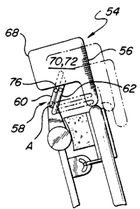
Referring to Figures 2, 8A and 8B, the
adult backrest portion 14 includes a first lower
portion indicated by the child seat portion 24 as
described above and a second upper portion forming
a child headrest 54 pivotal about an axis A between
a folded position recessed in the cavity 20 forming
the upper portion of the adult backrest 14 and an
unfolded position pivoted upwardly and extending at
least partially above the upper portion of the
adult backrest 14 to form an extended child
backrest 26 and/or child headrest 54. The second
upper portion or headrest 54 includes a front face
56 forming a portion of the adult backrest 14 in
the folded position and aligned in a parallel plane
with the child backrest 26 forming an extended
portion thereof in the unfolded position as shown
in Fig. 8B.
20954~2
P-945 13
The child restraint seat 22 is further
characterized by including pivot means 58
interconnecting the second upper portion or child
headrest 54 and the adult backrest 14 for pivoting
the upper portion 54 in an arcuate orbital path
spaced from the axis A from the folded position to
the unfolded position to provide an extended child
seat backrest height and headrest support. The
pivot means 58 includes a pair of linkages 60,62
each having a first end pivotally coupled to a
bracket 63 extending upwardly from the upper
support beam 36 of the main support frame 34 and a
second end pivotally coupled to the headrest 54.
The headrest 54 comprises a generally L-
shaped shell 68 having first and second sides 70,72
and generally covered in a resilient foam material
and fabric upholstery as is commonly known in the
art. The headrest 54 is received in an upper L-
shaped region 74 in the cavity 20, Figure 2, to
form a portion of the adult backrest 14. The
linkages 60,62 are coupled on the opposite sides
70,72 of the shell 68 and included a control rod 76
fixed at each opposite end to the linkages 60,62
and extending therebetween to prevent torsional
deflection of the shell 68 upon rotation from the
209~2
P-945 14
folded to unfolded positions. As shown in Figures
8A and 8B, the arcuate pivotal movement of the
headrest 54 provided by the pivot means 58 allows
the structure of the pivot means 58 including the
bracket 63 and linkages 60,62 to be positioned
behind the child backrest 24 and generally seating
area and thereby facilitates use of a structurally
rigid pivot means 54 for positioning the headrest
54 in the desired folded and unfolded positions
while preventing
any contact of the rigid structure with any portion
of the child occupying the seat; especially the
child's head.
As can be appreciated, each of the child
seat portions 24 and backrest portions 26 are
generally covered in a layer of resilient foam
material and fabric upholstery to provide passenger
comfortability to both the adult and child.
Howev,er, the assembly is further characterized by
one of the child seat portion 24 or backrest
portion 26 including a suspension system as
generally indicated at 78 in Figures 7, 9 and 10.
A secondary support frame 82 is disposed
between the child backrest area and the main
2~95~12
P-945 15
support frame 34. The secondary frame 82 includes
a plurality of opposite side support bars 84
interconnected by upper 85 and lower 87 cross
members to form a rigid framing. The secondarv
support frame 82 is pivotally coupled to the upper
support beam 36 by the pivot coupling 47,48 as
shown in Figures 4 and 5. A support bracket 47
extends outwardly from the upper cross member 85
and interconnects with the pivot bracket 48 as
described hereinabove. The support bracket 47 and
pivot bracket 48 are spaced below the upper support
beam 36 thus defining the upper support beam 36 as
the center of rotation of the secondary frame 82.
That is, the arcuate slot 52 in the bracket 47
allows the secondary frame 82 to rotate or pivot
about an axis defined by the upper support beam 36
upon movement from the upright to tilted positions.
This allows the rigid structure of the pivot
coupling 47,48 to be positioned outside of the
general child seating area defined between the side
support bars 84 and cross members 85,87 of the
secondary frame 82 ar.d thus eliminates any contact
of the child with the rigid structural components
of the seat.
2~9~4~2
P-945 16
Referring again to Figures 7, 9 and 10,
the suspension system 78 includes a plurality of
generally parallel resilient torsion bars indicated
at 80 suspended by the secondary support frame 84
for providing resilient seat support in both the
child seat 22 in the unfolded position and the
adult backrest 14 when the child seat 22 is
recessed in the cavity 20 in the folded position.
The suspension system 78 in the preferred
embodiment is commonly referred to in the seating
art as "Flex-o-lator" and comprises a plurality of
parallel torsion bars 80 composed of a solid
helical wrapping of paper filament or a single wire
strand helically wrapped in paper filament. The
stands are interconnected by a plurality of
crossing wire strands 81 to form a resilient flex
grid as shown in Figure 9. The grid is then
suspended by a plurality of springs 86 extending
from the side support bars 84 of the secondary
frame 82. As can be appreciated, the suspension
system may take on many forms, configurations and
utilize many different materials as are commonly
known in the seating art. Also as shown in Figure
10, an additional torsion bar 80 or flex wire may
extend forwardly from the side support bars 84 to
2~95~12
P-945 17
provide resilient support in the seat bolster areas
18.
The secondary support frame 82 remains
independent from the main support frame 34 to allow
the secondary frame 82 to be encapsulated in foam
during the foam molding process. In other words,
durinq manufacturing of the vehicle seat, the foam
cushion portion is often molded from a liquid foam
poured into a mold cavity to form the seat
configuration. The process is generally referred
to as "SURE-POUR" and is specifically described in
the assignee's copending application serial number
541,783. The "SURE-POUR" process allows the foam
to be molded about the secondary frame 82, thus
concealing the suspension system, eliminating seat
width and forming an aesthetically appealing and
comfortable adult and child seat. Further, as
shown in Figure 2, upon pivotal unfolding of the
child seat portion 24 to the unfolded use position
the entire bac~rest portion 14 formed by the
secondary support frame 82 pivots to the inclined
child seating position.
Finally, the secondary seat frame 82
includes a thin metal plate 88 forming at least a
portion of the upper cross member 85
209~12
P-945 18
interconnecting the opposite side support bars 84.
The plate 88 conceals or covers over the upper
support beam 36 as shown in Figures 5 and 9.
Referring to Figures 8A and 8B, an energy
absorption material barrier 90 is disposed between
the thin metal cover plate 88 and the upper support
beam 36. The barrier 90 may be composed of any
suitable energy or force absorbing material such as
styrofoam, rubber, plastic, or the like, substance
as is commonly known in the industry. The plate 88
and barrier 90 are seated in front of the main
support frame upper beam 36 to absorb any forces
exerted on the child seat backrest 26 and prevent
contact of the child with the rigid suppcrt frame
36.
Therefore, it is important to note that
each of the rigid fixed points of the seat support
structure including the upper support beam 36 and
secondary frame 82 are covered or spaced from
contact with the child utilizing the seat by some
type of energy absorption material or barrier.
Furthermore, it is equally important to note that
the pivotal connections between the child seat
portion 24 and backrest portion 26 with the lower
support beam 38 and between the headrest 54 and
2095~12
P-945 19
upper support beam 36 and finally between the
backrest portion 26 and pivot bracket assembly
37,38 are each displaced at a position spaced
behind and outside of the general child seating
area defined between the side supports 84 of the
secondary frame 82 and thus prevent any possible
contact by the child occupying the seat.
The invention has been described in an
illustrative manner, and it is to be understood
that the terminology which has been used is
intended to be in the nature of words of
description rather than of limitation.
Obviously, many modifications and
variations of the present invention are possible in
light of the above teachings. It is, therefore, to
be understood that within the scope of the appended
claims wherein reference numerals are merely for
convenience and are not to be in any way limiting,
the invention may be practiced otherwise than as
specifically described.