Language selection

Search

Patent 2095552 Summary

Third-party information liability

Some of the information on this Web page has been provided by external sources. The Government of Canada is not responsible for the accuracy, reliability or currency of the information supplied by external sources. Users wishing to rely upon this information should consult directly with the source of the information. Content provided by external sources is not subject to official languages, privacy and accessibility requirements.

Claims and Abstract availability

Any discrepancies in the text and image of the Claims and Abstract are due to differing posting times. Text of the Claims and Abstract are posted:

  • At the time the application is open to public inspection;
  • At the time of issue of the patent (grant).
(12) Patent: (11) CA 2095552
(54) English Title: METHOD OF CONVERTING TRACTION MOTOR SUSPENSION SYSTEM
(54) French Title: METHODE DE CONVERSION D'UN SYSTEME DE SUSPENSION DE MOTEUR DE TRACTION
Status: Deemed expired
Bibliographic Data
(51) International Patent Classification (IPC):
  • B61F 15/12 (2006.01)
  • B61C 9/50 (2006.01)
(72) Inventors :
  • POPOVITS, STEPHEN (Canada)
  • STASIAK, KRZYSZTOF (Canada)
  • PAUCH, EDWARD (Canada)
  • VAN DE GRAAF, ADRIAN (Canada)
(73) Owners :
  • PROGRESS RAIL CANADA CORPORATION (Canada)
(71) Applicants :
(74) Agent: FINLAYSON & SINGLEHURST
(74) Associate agent:
(45) Issued: 2000-12-12
(22) Filed Date: 1993-05-05
(41) Open to Public Inspection: 1994-11-06
Examination requested: 1997-08-28
Availability of licence: N/A
(25) Language of filing: English

Patent Cooperation Treaty (PCT): No

(30) Application Priority Data: None

Abstracts

English Abstract


Locomotive traction motors have conventionally
been used in North America with sleeve-type friction bearing
suspension systems. Roller bearing suspension systems have
been gaining acceptance in North America. There is no known
method of converting the sleeve-type systems to roller
bearing systems. This problem is overcome by a method in
which the bearing caps covering the sleeve bearings, the
sleeve bearings and the shaft are removed; recesses are
formed in the bearing caps and in the traction motor housing
proximate the ends of the traction motor for receiving
roller bearing housings at each end of the traction motor
housing; installing the roller bearing housings on an axle
and in said recesses in the bearing caps; mounting a
generally U-shaped cover between the bearing caps, the
U-shaped cover and bearing caps surrounding the central
portion of the axle; and connecting the bearing caps to the
traction housing.


Claims

Note: Claims are shown in the official language in which they were submitted.


THE EMBODIMENTS OF THE INVENTION IN WHICH AN
EXCLUSIVE PROPERTY OR PRIVILEGE IS CLAIMED ARE DEFINED AS
FOLLOWS:
1. A method converting a locomotive traction
motor sleeve-type bearing suspension system to a roller
bearing system wherein the bearing system includes bearing
caps covering sleeve bearings mounted in a traction motor
housing and rotatably supporting a conventional wheel axle
the method comprising the steps of (a) removing the
bearings, bearing caps and the axle; (b) forming recesses in
the bearing caps and in the traction motor housing proximate
the ends of the traction motor for receiving roller bearing
housings at each end of said traction motor housing; (c)
installing the roller bearing housings on an axle and in
said recesses in the bearing caps; (d) mounting a generally
U-shaped cover between said bearing housings, said U-shaped
cover and said bearing caps around part of the central
portion of an axle; and (e) connecting said bearing caps to
said traction motor housing.
2. A method according to claim 1, including the
step of installing grease tubes in said bearing caps for
feeding grease to said bearings.
3. A method according to claim 1, including the
step of installing shims between said cover and one said
roller bearing housing for adjusting the length of the
suspension system.

Description

Note: Descriptions are shown in the official language in which they were submitted.


209~~~2
This invention relates to a method of converting a
locomotive traction motor sleeve-type bearing suspension
system to a roller bearing system.
Locomotive traction motors have been manufactured
in North America since the 1950's. Roller bearings have
been used with such motors for locating a drive axle in
relation to the traction motor and for maintaining spacing
for the drive gears. Examples of roller bearing systems are
disclosed by United States Patents Nos. 2,742,864, issued to
R.B. Enyart on April 24, 1956, and 3,138,115, issued to M.N.
Waite on June 23, 1964. The use of roller bearings has been
restricted to Europe where such bearings gained acceptance
in the 1960'x. ' Roller bearings have only recently been
adopted in Canada. Early units experienced failures, but
the problems have been solved and current units appear to be
operating in a satisfactory manner.
To date, no successful method has been developed
to convert the old style sleeve-type bearing suspension
system to the new style roller bearing system. One proposal
is to replace the entire traction motor and bearings with
new unite, or the replacement of the motor housing.
The object of the present invention is to solve
the conversion problem by providing a relatively simple
method of converting a locomotive traction motor sleeve-type
bearing suspension system to a roller bearing system, the
method requiring minimum modification to existing equipment
and therefor minimum cost.


--1 209~~~2
Accordingly, the present invention relates to a
method converting a locomotive traction motor sleeve-type
bearing suspension system to a roller bearing system wherein
the bearing system includes bearing caps covering sleeve
bearings mounted in a traction motor housing and rotatably
supporting a conventional wheel axle the method comprising
the steps of (a) removing the bearings, bearing caps and the
axle; (b) forming recesses in the bearing caps and in the
traction motor housing proximate the ends of the traction
motor for receiving roller bearing housings at each end of
said traction motor housing; (c) installing the roller
bearing housings on an axle and in said recesses in the
bearing caps; (d) mounting a generally U-shaped cover
between said bearing housings, said U-shaped cover and said
bearing caps surrounding the central portion of the axle;
and (e) connecting said connecting said bearing caps to said
traction motor housing.
The invention will be described in detail with
reference to the accompanying drawings, which illustrate a
preferred embodiment of the invention, and wherein:
Figure 1 is a longitudinal sectional view of a
locomotive traction motor bearing suspension system in
accordance with the prior art;
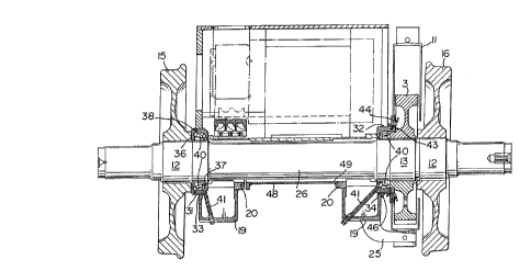
Figure 2 is a longitudinal sectional view of a
roller bearing suspension system following conversion from
the system of Fig. 1;
2


~0~~5~2
-.
Figures 3 and 4 are end views of a portion of a
traction motor housing as seen from the left and right,
respectively of Fig. 2;
Figure 5 is a side view of the traction motor
housing with bearing housings, bearing caps and a shaft
cover mounted thereon as viewed generally in direction A of
Figs. 3 and 4;
Figure 6 is a plan view of the bearing housings,
bearing caps and shaft cover of Fig. 2, with parts omitted;
Figure 7 is a side view of the bearing housings,
bearing caps and shaft cover of Fig. 6 with parts omitted;
Figure 8 is a bottom view of the bearing housings,
bearing caps and shaft cover of Figs. 6 and 7;
Figure 9 is an end view of one half of a bearing
~ housing, and a bearing cap as viewed from the left of
Fig. S;
Figure 10 is an end view of a bearing housing arid
a bearing cap as viewed from the right respectively of
Fig. 6;
Figure 11 is a cross section of one end of the
shaft cover of Figs. 6 to 8 illustrating a mounting flange;
Figure 12 is an end view of the modified traction
motor housing and shaft suspension system as viewed from the
left of Fig.'2;
Figure 13 is an end view of the modified traction
motor housing and shaft suspension system as viewed from the
right of Fig. 2, with parts omitted.
3
:,,t.a


209~~~~
With reference to Fig. 1, a conventional traction
motor 1 is mounted in a housing 2 for driving a gear 3
mounted on an elongated shaft 4. As best shown in Figs. 3
to 5, the housing 2, (only a portion of which is shown)
includes openings 6 and 7 in the ends 9 and 10, respectively
thereof. A cover 11 protects the gear 3. The shaft 4
includes larger diameter portions 12 and 13 which act as
seats for the gear 3 and a pair of wheels 15 and 16. A pair
of cylindrical, sleeve-type bearings 17 are provided on the
shaft 4 permitting rotation thereof. The bearings 17 are
mounted in a semicylindrical recess 18 in the housing 2.
Oil caps 19 are mounted on each of the bearings 17 for
lubricating the shaft 4 and the bearings 17. As best shown
in Figs. 6 to 8, each cap 19 has a thick mounting flange 20
for connecting the cap to flanges 21 (Figs. 3 to 5) on the
housing 1. An opening 23 in the caps 19 is aligned with an
opening 24 in the bearing l7 so that oil contacts the shaft
4 and the bearing 17. One of the caps 19 includes an r
arcuate arm 25, which supports the gear cover 11.
The first step in converting the shaft suspension
from the sleeve-type bearing system to a roller bearing
system is to remove the oil caps 19 and the bearing 17. The
shaft 4 is replaced by another shaft 26, with a longer seat
13I. The housing 2 is machined at both ends to form
semicircular recesses 28 and 29 at the ends thereof for
receiving roller bearing housings 31 and 32. Recesses 33
and 34 are also formed in the oil caps 19 for the same
4


~0~~5a2
purpose. The bearing housing 31 at one end of the traction
motor 1 is a two-piece annular assembly defined by two
halves 36 and 37 with a labyrinth seal 38 where the halves
are joined. Roller bearings 40 are mounted in the housings
31 and 32 for rotatably supporting the shaft 4. Grease
tubes 41 are mounted in the oil caps 19 for carrying grease
to the bearings. The other bearing housing 32 is a one-
piece annulus of L-shaped cross section, the open end
thereof being closed by the gear 3. A labyrinth seal 43 is
provided between the open end of the housing 32 and a
shoulder on one side of the gear 3. An annular gear cover
seal 44 is provided between the open end of the housing 32
a.nd the gear cover 11,. A reinforcing gusset 46 extends
between the oil cap 19 and the bearing housing 32.
The modification is completed by a generally U-
shaped cover 48 which is welded at one end 49 to one oil cap
19. The cover 48 extends around the shaft 4 to protect the °y
latter. A semicircular flange 50 is provided on the other
end of the cover 48. A plurality of holes 52 are provided
in the flange 50 for receiving bolts 53 (Fig. 11) which
connect the flange to the flange 20. Shims (not shown)
having generally the same shape as the flange 50, and holes
for alignment with the holes in the flange are used to
adjust the length of the cover, i.e. to adjust the length of
the bearing support assembly. Thus, there is no looseness
in the two bearings. Gussets 55 are normally provided on
,,.
r;


2~~J5J~
the sides of the bearing caps 19. Additional reinforcing
gussets 56 (Fig. 5) are added to the motor housing 2.
6

Representative Drawing
A single figure which represents the drawing illustrating the invention.
Administrative Status

For a clearer understanding of the status of the application/patent presented on this page, the site Disclaimer , as well as the definitions for Patent , Administrative Status , Maintenance Fee  and Payment History  should be consulted.

Administrative Status

Title Date
Forecasted Issue Date 2000-12-12
(22) Filed 1993-05-05
(41) Open to Public Inspection 1994-11-06
Examination Requested 1997-08-28
(45) Issued 2000-12-12
Deemed Expired 2005-05-05

Abandonment History

There is no abandonment history.

Payment History

Fee Type Anniversary Year Due Date Amount Paid Paid Date
Application Fee $0.00 1993-05-05
Registration of a document - section 124 $0.00 1993-10-22
Maintenance Fee - Application - New Act 2 1995-05-05 $100.00 1995-04-10
Maintenance Fee - Application - New Act 3 1996-05-06 $100.00 1996-05-03
Maintenance Fee - Application - New Act 4 1997-05-05 $100.00 1997-05-05
Request for Examination $400.00 1997-08-28
Maintenance Fee - Application - New Act 5 1998-05-05 $150.00 1998-05-04
Maintenance Fee - Application - New Act 6 1999-05-05 $150.00 1999-05-04
Registration of a document - section 124 $100.00 2000-02-02
Maintenance Fee - Application - New Act 7 2000-05-05 $150.00 2000-05-04
Final Fee $300.00 2000-09-08
Maintenance Fee - Patent - New Act 8 2001-05-07 $150.00 2001-04-12
Maintenance Fee - Patent - New Act 9 2002-05-06 $150.00 2002-04-19
Maintenance Fee - Patent - New Act 10 2003-05-05 $200.00 2003-04-22
Owners on Record

Note: Records showing the ownership history in alphabetical order.

Current Owners on Record
PROGRESS RAIL CANADA CORPORATION
Past Owners on Record
CAE VANGUARD, LTD.
PAUCH, EDWARD
POPOVITS, STEPHEN
STASIAK, KRZYSZTOF
VAN DE GRAAF, ADRIAN
Past Owners that do not appear in the "Owners on Record" listing will appear in other documentation within the application.
Documents

To view selected files, please enter reCAPTCHA code :


To view images, click a link in the Document Description column. To download the documents, select one or more checkboxes in the first column and then click the "Download Selected in PDF format (Zip Archive)" or the "Download Selected as Single PDF" button.

List of published and non-published patent-specific documents on the CPD .

If you have any difficulty accessing content, you can call the Client Service Centre at 1-866-997-1936 or send them an e-mail at CIPO Client Service Centre.


Document
Description 
Date
(yyyy-mm-dd) 
Number of pages   Size of Image (KB) 
Representative Drawing 1998-08-20 1 33
Representative Drawing 2000-11-14 1 17
Claims 1999-12-15 1 36
Cover Page 1995-04-08 1 70
Abstract 1995-04-08 1 68
Claims 1995-04-08 1 49
Drawings 1995-04-08 9 474
Description 1995-04-08 6 353
Cover Page 2000-11-14 1 50
Correspondence 2000-03-02 2 57
Correspondence 1997-07-14 1 1
Assignment 1993-05-05 5 176
Prosecution-Amendment 1997-08-28 1 54
Fees 2000-05-04 1 37
Fees 1998-05-04 1 41
Correspondence 1997-07-14 1 1
Correspondence 1997-04-22 6 152
Correspondence 2000-09-06 1 2
Correspondence 2000-09-06 1 1
Assignment 2000-08-28 1 33
Correspondence 2001-08-08 2 39
Correspondence 2000-09-08 2 42
Prosecution-Amendment 1999-06-16 2 2
Assignment 2000-02-02 4 107
Correspondence 2000-02-29 1 1
Prosecution-Amendment 1999-12-15 3 75
Fees 1999-05-04 1 40
Fees 1997-05-05 1 54
Fees 1996-05-03 1 46
Fees 1995-04-10 1 49