Note: Descriptions are shown in the official language in which they were submitted.
2 ~ 9 ~ ~ ~ 2 PCI/USg1/08$63
VO 92~09006
~UT~5TEREQ5;~0~ PI~E~iENTATIQN.~Y'TEM
C~HNIkAI, E~ELn
he invention pertain~ to the general field of
threP-dimensional presentations and more p~rticul~rly
to an autostereoscoPic presentation that utili es a
plurality of non-movin~ screQns in combination with
~ynchroni2ed image prQjections to produce a percelved
three-dimensional im~ge.
~A~K~RQUND ART
rhe que~t tc~ F~rodurP qualitY and
technicallY-effective three-dimensional ima~e~ has
continued ~or a numb~r of years. Ba~ically, there are
two tYpes of pre7entati3n methods or systems that are
availablP for ~iewin~ threG-dimensional images: thes~
are broadlY characterized ~5 either ~tereos~opic or
autostereoscoPiC
Irl stereoscoPi~ sy-tems, pairs of ordinary
two-dimensional ,till photo~raph, or bil-,ocular motion
pictures are made of an object from two Points of view.
-rhe two poi.nts are seParated by a distance equal to the
di~tance between the eyes of a viewer. The Pair of
Photo~raphs or motion picturPs arP then viewed by a
device that ~llows the risht eye to see onlY the right
im.~ge ~nd the left eYe only the le~t image. In this
viewing system, each eye sees a slightly different
image; thereby duPlicatin~ the conditions under which
the ori~inal scene would havP been viewed.
~onsequ_ntlY~ the viewer is aware of only on~ im.~e
that has a three-dimensional effect.
TC vi~w objects ~tere~oco~ically, the stereo
photo~raPhs or movir,~ ~ictures must be separated by an
opaque area that allow7 tho ri~ht ey~ to see only the
rinht view and the left ei~e only the left view.
- , .
.
- - ~
- .
- - . . ., - ~ .
- ~ . .. , ; ~,. . ~,,
.. ... .. . . .
WO~/09006 2 ~ 9 5 G ~ ~2 rcT/us9l/o~s63
several ~ystErn, havE ~ee~ de~ised to Permlt
stereoscoPic Yiewin~. For example~ red and green
tinted monochrome images are both displayed to be
viPwed bY glasse~ havins left and risht len5es with
corresponding red and green tints; or two color imagPs
are projected thro~gh mutually perpendicul2r polari~ed
~ilters and are then viewed thro~gh sl~sses that are
p~lari~ed in the same mannsr~
In autostereo5coPiC sYstem-l~ it is not necessary
for thP viewer to wear 5pecial ~lasses or to use any
other vieh~ins im~lement to keep the two images
seParated~ What the viewer ~ee- is not the pair o~ two
dimensional images a~ described a~ove, but rather a set
of imaQe~ that either appear to bP di~tributed over
three dimensions or are aetually di,tributed over three
dimensions. A holo~raPhic image i 5 ~ n example of the
first type of a~tostereoscopic imaging. The second
type of aut 05 tereo,coPic imagin~ i~ currentlY achieved
by the use cf movin~ --creen~ or vibrating varifocal
mirrors that are vibrated ~y an 05Ci 1 l~ting frequency
that causes the ~irror to have a continuously varia~le
focal length. In both tYpes~ the imase is constantly
moved back and foFth in the image space provided. ~his
movement causes the imagPs to fu5e together and because
of the persistence of the eyes ~ three-dimensional
image i5 perceived.
A search of the prior art did not disclose any
patents that redd dire~tlY on the claims of the instant
invention howe-ver, the following U.5. patents were
~onsidered related:
PATEhl~l NO. ;~N~)El`ITOR I55UED
4,747,665 O'Bri~n 31 May 1S88
4,714,31q Zeevi et al ?f December 1q87
4,571,041 ~auds~r, 1~ ~ebruary 1q~6
3., ?48, 165 Marks et ~1 _S APril 1q66
~ . . . .
.. . . , _ . . .. . . . . . .
.
..... . . ..
; . - . . ~ ~
~ " ~ " . i ,~,, . ", ,.
:, : . ., -. -.. : ~
2~956~
~o9~/09~6 PCT/US91/0~563
The O'Brien patent discl 05 es a method for
displaying three-dimensional imases. ~he method
consists of driving a flexible membrane mirror by ~
comPosite waveform th~t consi~ts of triangle and
sinusoidal waves. The comPOsite waveform displaces the
flPxible membrane mirror ~o that the mirror's surface
is alternatelY convex and concave. The drivin~
wavPforms are then synchroni~ed to di5play an
alternating sequence of two-dimensional images on a ~RT
5creen sucll that the viewer p~rceives a
three-di~ensional ima~e.
The Zeevi et al patent discloses a method of
~enerating disParate information for impartin~ depth
percePtion to an ima~e. The dePth Perception i5
creatPd by Projectins ~n image of an obiect u~ing a
plurality of energy sources to create a plurality of
images having different 5hadow5. A single detector,
such as a camera, detect~ and 5ucce~sivelY records the
object with the object illuminated for successive
frames from li~ht source~ at spaced ~part location~.
wllen ~iewed, the image will have a thr~e-dimensional
effect that in sub~tance, i~ a shadswsra~ ha~in~ an
illusion of depth.
The ~aud~n patent discloses a three-dimensional
Frojpcti3n arrangement for proiecting dual
three-dimen~ional image~ of obiPcts into space for
viewing bY an unaided audience. The obiects are
illuminated by a ~ource of light, and the light rays
reflected from the ohiects are directed 50 as to be
incident on a mirror surface lscated behind a lens and
the combination form~ the enlarged three-dimen~ional
ima~e that are Froiected into space. The lens can be
in the form of A mod.ified fre~nel lens that provides a
sub~tantially large field of view.
. .
.
. . . .. . .
. . .
..~ :..,,.. ;
- ~.. . . . ..
. . ~ . . .,; - . .
. . -. , .
.
2095612
wos~/o9~o6 PCT/US9~/0~563
The Marks et al patent disc 105 es a moving 5creen
proiection system that 3imulates a three-dimen5ional
presentation. The 5y5tem include5 Plural Projectors
that are combine~ with at lea5t two viewing screen
spaced from each other. The multiple screen system
include~ 1) a foreground reflectins sur~ace having
holes for pas5ing 50m~ of the Projected light, 2) a
Polari~ing film on the screen whic}l Pag5e5 onlY light
polari?ed in a fir5t plane, and 3) a diffu5ing layer
that diffu~as the reflection~ of tha lncldent ll~nt. A
bac~ground ~creen is mounted behind the foreground
screen for receivins and reflecting light passed
through the hole~.
~ LQSURE OF THE INvE~ION
The autostereo~coPiC Presentation system utili~es
a comPuter enhanced film strip having a multiplicity of
photographic frames. Each frAme has a two-dimensional
optical image where the oPtical image of the first
frame has a fore~round of a sc~ne that aPpears as a
conventional image that is an image as normally seen,
and .~ bac~.ground that appears as a black or matted
imase hereinafter matted imase. The succeeding second
Irame h~s an optical image that ha, a background of the
same scene that no~ aPpear~ a~ a conventional image
~ith a fore~round th~t aPpear~ a~ a matted image. The
remaining and succeeding frame pairs rapidly alternate
- their oFtical image5 ~5 dPscribPd abovP with
appropriate movement of the optical image, in the case
of motion picture~.
A projector is used that provides the means for
projecting the enhancPd film strip onto at least two
~tationary ~creens that operate in either a translucent
mode or a clear mode and that are juxtaposed in Planar
~eparation from each other. The screen nearest the
~ , . - - - . .
- - - - - -
,.. , ... :.. . , . .- :. :
- .. . ., , :
. ~ .. .; - ~ , ...
- : - . . . ;, . i . , ~
- ~ ... . , - ~.. . "
. , - , ..
; ..
~ ~2/~go06 2 0 9 ~ G ~ 2 PCT/US9l/08563
viewer is referred to a5 the foreground screen while
the remainin~ screen~5) are referr~d to a5 the
bac~round screen~s~. The sYstem basically functions
bPcause of the p~rsi~tance of vision. In othPr word~,
5 the eyes will retain the fir,t Projected imag~ while
~ the ~econd ima~e i5 beinQ Proiected~ rhus, their is a
fusion of imases that result in a sin~le perceived
three-dim~n~ional imaq~. Addition~lly, by alternately
proiecting two ima~es there i~ an effective overlaY of
images which re5ult~ in ~ hisl-,-de~initioll picture. To
avoid flicker, the fore~round and back~round imayes are
e~ch proiected at a rate o~ at least ~6 time~ Per
-econd.
To operate the sy5tem~ a means i provided for
,electin~ and controllin~ the op~ration~l modes of the
screen~, ~nd for synchroni~in~ the operational modes of
the screens with the resPective alternating projections
of the two-dimen~ior~al oPtical imaYes~ At any one time
period, onl~ one conventior~al ima~e i, Projer~ed onto
the specific screen th~t is operating in its
translucent mode. For example, in a back projected
desisn when the backg~ound ~creen is in its clPar mode,
the IorPground image i5 synchronously projected throu~h
the clear back~round screen and onto the translucent
fore~round screen. ~onversely, when the foreground
screen is in its clear mode, the back~round image is
ynchronou~ly ~rojected into the translucent background
screen. In this instant, the back~round screen is
viewed through the clear fGresround screen.
In view of the above disclosur2, it i5 the
primary object o~ the invention to Provide an
auto~tereosco~ic Fresen~ati6n sYstem that functions by
alternatPly ~rojectin~ o~tical ima~es onto stationary
screens that oPE~ate in synchronously selected
operation.~l modes. rhus, the sy,tem ~llows a viewer to
perceive a three-dimensional volumetric image without
.. . . . . . . ..
- - - .
:s- . .
~09~6~2
W0~2/09006 PCT/US9l/08563 -~
the need for a viewing implement. In addition to the
primary object, it i5 al~o an object of the invPntion
to have a sYstem that: .:
o can be ~sed as~a conventional film Projection
~ystem or that can be modified to allow
tele~ision transmitter to broadcast special
film th~t would be r~ceived by a telQvislon
recei ver,
o operate~ with 5tationary ~creens,
o is reliable an~ easilY maint~ined
Q can function with either color or bl~ck and
white Positive transp~renciPs,
o is preferablY but not limited to back
projection;
o can utili~e currently available computer
enhancement techni~ue~ ~o prepare the film
strip or slides required by the 5y5tem,
o can be made with scrPens of various si~es, and
o can be used for three-dimensional display
advertisin~.
BRI~ ~E5~RIPl`l&N OF THE~ DR~kllNq5
FI~URE 1 dPpi~ ilm striP segment h~ving a
first and a second phcto~raphic frame.
FI~URE ~ is a perspective view of an
autostereoscoPic presentation system con~istin~ of a
sin~le projector and two screens.
FI~UP~E 3A dEPict~ ~ sir~gl~ prci~ctGr Pr~iectins a
two-dimensiorl~l foreground ima~e onto a transl~cent
fore~round screen throu~h a clear background screen.
.
.. . .
: . . . , . - -- - - - -
- -, - - - - --- -
. . , -. : . ~,.
, ~.-.. . .
. . . . . .
` ~vo g2/09~0~ ~ 0 9 ~ ~ ~ 2 PCT/US91/08~63
FI~U~E 3e dePicts the sinsle Projector Projectin~
the two dimensional backsround im~ge onto translucent
backsround screen a5 viewed throu~h a clear foresround
~creen.
FI~URE 4 depicts the resultant three-dimensional
~Qlumetric image that i~ perceive~ by a viewer because
of the ~eparation of the ima~es.
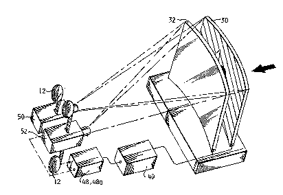
FI~URE 5 is a perspective view of an
autostereoscoPic Presentation sYstem consisting o~ two
Proiectors and two scre~ns,
FI~U~E 6 dePict~ the configuration of a first
film ~tri~ that would be u~ed with one o~ the
Projectors a~ shown in FI~URE 5.
FI~URE 7 dePict~ a configuration of a second film
striP that would be synchroni ed with the fir~t film
~trip of FI~URE 5 and proiected through a second
roiect~r.
FI~URE o i5 ~ 5ide vi~w showins the u5e of three
~creen~ and a fre~nPl len~ located in front of the
forenround screen.
FI~URE q depicts an examPle of a multiple film
,trip, in thi~ case a three frame film ~trip, that
would be used with the three ~creens as sh3wn in FI~URE
~. ~he frame~ would ~how forP~round, middle ~round and
back~round images.
FI~URE 1D is a top view of a movable screen that
is located bPtween th3 forE~r~und and background
screens and that rotate~ hori~ontally.
, , - . - .
.. . . . . . ..
, :
, . .
- . . - j.
~ ~ - - ....
wo 92/0go06 2 0 9 ~ 6 1 2 PCT/USsl/08563
FI~URE ~ a sid~ view of a movable screen that
i~ located between ~he fare~round and background
screens and that rotates vertically,
FI~URE 1? is a block diasram of the system
S ~howin~ the timin~ and ~Ynchroni~ins circuit connected
to two screen~.
. . . . . . .. . ... .. .. . . . . . . . . . . .
,: . ,,.. ;
.. . .. . .
- . , . . , , -
~:VO 92/090~16 2 0 9 ~ PCI`/US91/OB563
ESr M~r~E F~ ~YIN~ ~llT THF. L~lvENTToN
The best mode for carryin~ out the
autostereoscoPiC presentation 5y5tem 10 i5 presented in
.terms of a preIerred embodiment that i5 primarily
designed to ~rQvide 5eParate fGresround and back~round
two-dimPn~iona1 ima~es to a viewing audience who then
perceive a three-dimen~ional volumetric lmage t~at 1
~iewed without ~ny vi ewins im~lem~nt 5.
~he preferred embodiment, as shown in FI~URE5 1
throu~h 1~2 i~ comPrispd of the f~llowing m~jor
elements: an enhanced film strip 1~ havlns a
m~ltiplicitY of 5equential photographic framPs, a
station~ry foreground screen 30, ~ stationa.ry
background screen 32, a timing and ~ynchroni~ins
lS circuit 40, a light respondin~ circuit ~8 and a
conventional projector -50.
In describing the preferred embodiment, the
multiplicitY of photosraPhic frame, is limited to a
first Photosraphic frame 14 and a second photographic
IramP 18 as shown in FI~URES 1A and 1B. The first
frame 14 includes a first two-dimer,siorlal optical image
16 h~vin~ d fore~round thAt appears ~5 a conventional
image 16a and re}ated back~round that appears as a
matted image 16b and 16c. The matted ima~e 16c in
actualitY would also be matted and would be
indistinguishable from thP ima~F 16b~ However, for
visuaI clarity and exPlanatory purposes,the image 16c
is shown with cross-hatching. rhe following second
photo~raphic frame 18 consist, of a second
two-dimensional optical image ~D having reversed
ima~es, that i5, the related background now appears as
- a conventional image ~Da and thP fore~round appPars as
a matted ima~e ~Ob and ~oc. As described above, for
vi~ual cl~rity, the ima~e 20c i~ shown with
cros~-hatchin~. ~he oPtical images maY be Positive
- . - - ,
.. . . . . , . . .. . . .. .. . . . , ~ . . ....
.. : . - .
- , - ~ '. ,, . ~
,. . .
.. ..
. ,, ~, , , , .- -
- , ,, , ~ . :, ,
.. . .
209~61 ~
W~9~09D~6 PCT/US91/08563
color tran~parencies or positive black and white
transpdrencies .
The film format of the preferred embodiment is
operated through the 5ingle double 5peed ProjQctor ~0
S that bac~ Project~ the optical image 16,18 onto a
plur~litY of StationarY gcrePn~. The screens are
juxtapositioned and located in Planar 5eParation from
each other and each scr~en oPerate5 in either a cloar
mode or a translucent mode. In its 5imple5t de5ign
configuration, the sY~t~m 10, as shown in FIGU~E~ 2, 3A
and 3B, operates with two screens where the screen
n~arest the viewer i5 con~idered ~h~ foreground 5creen
30 and the screen nearest the projector 50 i5 the
bac~round ~creel-, 3~. Tlle proiector 50 oPerates in
lS combination with the timins and sYnchroni~ins circuit
40, as shown in FI~UR@S ~, 5 and ~2, that Provide~ the
means for synchroni~ins the Proiection o~ the oPtical
images with the appropriate opPrational mode of the two
screens. The circuit ~0 i5 described infra.
For purposes of exPlanation/ recall that the
first optical image 16, ~5 5ho~ln in FIGURE 1~, has a
foreground that is Frocessed as a conventional image
16a and a bac~;ground imaae a~ a matted ima~e 16b; and
conversely, as shown in FIGURE 1~, the ~econd oPtical
imase ~o has a back~round in ~ conventional image 20a
and a foreground in a matted fini~h 20h. ~o commence
the viewin~ s~quence, as best depicted in FI~URES 3A
and 3B, the fore~round im~ a i, back projected
throu~h the background screen ~, which has been set to
its clear modP, onto the translucent foresround screen
30. ~he second oPtical image 1B i5 then Projected onto.
thP tr~nslucent background screen 3~ and is viewed
through the fore~round screen 30 which ha~ been set to
the cl~r mode. ~Y altPrnatin~ the two optical images
in ~Ynchroni~ation ~ith the respective operational mode
o~ the two separate screPns, the viewer i~ able to
.. . . . . . .. . . .
. .
- : . --, , . . :. -
..
- - : :: . ,
..... . , ~:
'- ', ~
- 209~ 2
'~092/09006 PCT/USsl/08563
11
percei~e. ac chown in FIGURE 4, a three-dim~n~ional
volumetric image without thP~ need for ~ viewing
implement. The rea50n a three-dimensional image i5
percPived is duP to the persi tence Qf ~i5ion. Thi~
persistence allows the eyes to retain the first
projecte~ image while the 5econd image i5 bQiny
proiected. Therefore, there is a fusion of the two
image~ which results in the Perceived thr~e-dimensiondl
ima~e. Also, by alternately projecting two images,
there is an effective overlay of the images which
results in a hi~h-~ain, hi~h-definition imaye.
The abovP descri~tion, i 5 applicable to a sinqle
film striP that is used with a single projector 50 as
shown in FIGURE ~ If two conventional but
synchroni~ed Proiectors are ~sed, as shown in FIGURE 5,
two film striPs 1~ would be required to Project the
oFtical imase~ onto the f&resround and background
scrPens. In this two-film 5triP configur~tion, the
first film striP 1_~ as shown in FI~URE 6, would have
a first photosraPhic frame 14 that depict a first
two-dimensional oPtical image 16 having a conventional
forenround image 16a and a matted bac~ground image 16b.
This film strip would be proiected by the first
projP tor 50, ~5 ,hown in FIGURE 5, onto the
translucent fore~round screen 30 throu~h the clear
back~round screen 32, At the same time the first frame
14 is bein~ prAjected, the cvrre~Fonclirls first frame 15
~n the ~ec~nd film ,trip, a, sh~wn in FIGURE 7, wol~ld
be a totally matted frame, therefore, no image would
be proiPcted. At the next frame pair, the first film
strip 12 would have a second frame 15 that i~ totally
matted and the second frame on the second film strip 1
wo~ld have a second two dimensional optical image ~0
that converselY dPPicts a conven~ional back~round image
~A-oa and a matted foreground ima~e 20b. This second
ima~e would be ,ynchror,i~Pd with the ~crPens 30, 3~ so
... . . ..
. - - - - -- ~ . . .
.
;' ~ ., .
wo 92~0900s 2 0 9 ~ 6 1 2 PCT/VS91/08563
12
that the ima~e i~ projected onto the transl~cent
b~cksround screen 32 an~ viewed through the foreground
~creen which has ~een switched to it, clear mode. The
subsequent Fr~iections would continue d5 shown in
FIGURES ~ and 7. The above technique als~ produces th~
three-dimen~ional volumetric image, as shown in FIauRE
4, with~ut the need for a ~iewing implement.
A film ~ctrip hdvin~ a multiplicity o~ sequential
photograPhic frames is preferred for vi~wing on the
syst~m 1~. HowevPr, the sY5tpm will al50 f~nction with
still ~lide transParencie5~ In this case, the perceived
three dimencional volumetric imdse 26 would ~ derived
from a first two-dimen5ional optical slide image 16 and
a ~econd two-dimencional oPtical slide ima~e 20 a~
described above. The two slide transparencies would be
operated bY a cli~e projector (not shown~ having means
for alternatelY moving and sYnchronously Projectins
each slide transParency onto the foreground screen 30
and background c,creen 32 in synchroni~ation with the
respectivP operation~l modes of the 5 creen,C,
- The film ,trip 1, or ~till clide~ are Prepared
by a computer enhancement techniquP that is well known
ir, the art and therefore is not described in detail.
~enerally, the comFuter enhancement ~PPar~tUs takPs
each oPtical ima~e of each exiStin~ frame and separates
it into two fr~mes. The first frame i, then enhanced
by t~kin~ the two-dimensional optical imaye and
sep~ratin~ the rore~round into a ccnvention~l image and
the back~round into a matted ima~e. kikewi~e, the
o~tical ima~e on the second IramP i5 cep~ratPd into a
con~enticnal back~round irna~e and a matted fore~round
image. Tn lieu of usin~ comPuter enhanced film, the
object to be ~iewed ~ould be filmed by u~ing two
cameras. In this procedurP, the fir~t camera would
film the conventional fore~round while the second
camera wo~ld film a Preparpd mattPd back~round. To
.. .
.- . - . .
~ ,~
- ~ .' - ~ ,' "' ~
. ~ -
~92/09006 2 0 9 5 ~ ~ ,3 PCT/US91/08563
film the second frame, the firct camera would film a
prePared matted foresround while the 5econd would film
a con~entional background.
Thé stationary fore~round screen 30 and the
stationarY background screPn 32 ~re each liquid cry~tal
screens that are constr~cted by a well known Process
that includes pro~idin~ a liquid crystal coating with
conductive surface~ between sheets of plastic. Each
~creen therehy h2s an electrical conductive Path that
terminates on the foreground screen 30 at A first
Dlectrodes ~Od and d second electrode 30b and on the
back~round screen 32 at a first electrode 32a and a
second electrode 32~. When no power i~ applied to the
electrodes, the liquid cryetal~ are arrayed in
curvilinear paths ~long the ~pherical walls of
li~ht-switchin~ cells. In this arran~ement, the liquid
crystals are positioned to diffract or scatter incoming
light to place thE screen in it, translucent mode.
When power i~ Applied to the Plectrodes, the result~nt
electric field rotates the liquid crystals within the
li~ht-switching cell~ ning thPm ~ith the electric
fields and their lisht-Propasation axi~. When this
condition exi~ts, the screen~ are in their clear mode
allowing light to Pass.
The screen~ ~3,~ are switched to their clear
mode when an interruptable volta~ i, aPPlied to their
respective electrodes. The interruptable voltage
prPferablY consists of an a-c voltage that may vary
between 55 and 120 volts. At 55 volts a-c the screen
~tarts to change from its tran~lucPnt mode to its clear
mode and at 90 volts a-c the screen provides maximum
clarity.
The screens 30,32 may be configured to be
~ubst~ntially fl,~t, a5 shown in ~I~URE 2; or in some
situati~ns screens that are sli~htly c~r~ed around the
center vertical ax~i~, a~ ~hown in FI~URE 5, may be
.
~ . :
.. . . . . . .. . . . . . . . . . . . . .
, . - , . . - . .:
, :. . - - - - -. - ~ - . . .
..
.. . .
:
wo g~/o~no6 2 ~ 9 ~ 6 ~ 2 PCT/US91/08563 ~~
14
employed. The 5 creens configuration as well a~ the
~quare vic?wins area ~nd their Planar separation is
dependent uPon the distance the viewer is situated from
the foregroun~ ,creen 30 and the limiting viewin~ angle
of the screens. TO ~iden the viewing angle, a
~ negative, cylindrical fresnel lens 33 m~y be locA~ed in
front of the fvreyround ~creen ~0 as shown in FI~URE 8.
In ~dditi~n, the bound~ry between the im~ge and the
matte on the film should not be 5harp, but should fade
away and slight distance into the matte.
To Provide increa5ed resolution for the Perceived
three-dimPnsional Pre~entationl three or more screens
may be emPloyed ac also shown in FI~URE 8 with three
screens. In this design 5cheme the 5creens function as
previouslY described with the excePtisn that a film
strip having a first second and third two-dimPnsion~l
optical image 16,10 and 24 would be required as shown
in FI~URE q. ~he middle optical image, in this case,
would contain a middle ground ima~e. Additionally,
when thr e or more screens are employPd, any of the
screens can ~e selected to be the backsround screen.
~h~ remaining scrPens, located towards the viewer,
would then be ,ynchronously set to provide either
descending or ascending degrees of the foreground
image. For example, ~ shown in FI~URE 8, if screen c
is the background screen, then screen~ ~ or A could be
sequentially placed in their tr~nslucent m~de and the
synchroni~ed fore~round image would be back projPcted
as shown. As with thE other viewin~ schemec, the
triple film strip and triPle screens Provide a
perceived three-dimen,ional volumetric presentation.
A further viewin~ refinement maY be achievPd by
including a movable screen 3~ that is located between
thP foreground screen 30 and the bac~ground screen 3~.
Two movable screen desi~ns are di~closed one that
rotates hori ontal ly about .~ pivot point 3~ 25 shown in
.... . . .. . . .. . . . . . . . .
.
.. .. . . . . . . .
. ., :
, ~
wo g2/0~006 2 ~ ~ S ~ 1 ~ P~/US9~/08~63
F I ~URE 1 0 and another that moves vertic~lly about a
PiVot point 35 ~s shown in FIGURE 11. TO utili~e these
screens, a mech~nism 3B having the means to focu5 the
~creen as the screen i5 b~ins moved i5 required. The
mechanism would also have the mean5 to operate in
combination with the electronic5 5ynchroni2ins circuit
to control the clear and translucent mode of the
screen 34. 8y utili~in~ thP movable scrQen 34 an
object such as a walkin~ per50n can be dimensionally
viswed in incrPmental hori~ontal or vertical movements.
Thus a refined three-dimension~l Per~eived ima~e can
be ~iewed.
The means for selectins and controllin~ the
operational modes of the foreground ~creen 30 and the
back~round screen 3~ and for synchroni2ins the
operational modes of the ~crPen- 30 3~ with the
alternating projections of the fir~t and second two
dimensional optical image 16,20 is provided bY the
tlming and sYnchroni~in~ circuit 4D.
The circuit 40 as shQwn in FI~URE 12 consi~ts of
an interruptable a-c voltage generator 41 a first
two-ir,put AND g~t~ 4L~ a sPcond two-input AND gate 44
and a cignal switchin~ circuit 46. The circuit 46
functions in combin~tion ~ith A first and second light
responding circuit 48,4~ that ~re optically connected
to the first and ~econd film Proipctors 50,52
respectful 1Y . The projectors oFerate with the film
strips 1~ th~t each further include ~ timing ~egment 28
located on the side of the film ~trip and at the
be~inning of each PhotosraPhic frame.
The first ~nd second light respondins circuits
4~ 4q each include a light emitterfdetector circuit
th~t in the preferred embodiment consists resPectful 1Y
of a in~rared emitter 4~.~ 4~a. rhese circwits include
further circuit means fcr producing a fir~t and second
timing pulse r~spectfully each time one of the timing
, . . . . . . . . . . . . . . . ... . . . . .. .. . . . .. . . . . .
.
- - . . - - ,.... . . ..... . .. .
.~. .
. ~
wo 92/09no6 2 ~ 3 ~ g ~ 2 PCT/~S~1/08563
16
segments 28 on the respective film strip 12 interrupts
the infrared beam and this is dete~ted bY ths infrared
emitter circuit.
The signal switchin~ circuit 46 has the means for
S detectin~ the first ~nd s~cond timinq pu15Q5 from the
~irst ~nd sQcond li~ht resPondin~ circuits ~8,4~. The
detection, in the preferred embodiment is Provided by
an infrared detector 46a located in the circuit 46,
When the timing and synchroni2ing circult 40 detects a
timing pulse, it produces a first or second timing
signal that is ~Ynchronously dpplied as the enabling
input to either the first or second two-inPut AND Yate
42,44~ The output o~ the ~irst AND ~ate 42 i5 a first
screen Power si~nal that is conne~ted to the first
electrode 30a of thP fore~round screen 30. A second
screen power signal from the second AND gate 44 i5
connected to the second electrode 3~ o~ the background
screen 3~. The second electrode 30b, 32b on each
screen is connectPd to ~round to complete the
electrical Path to the a-c voltase generator 41.
When the first ~ND gate 4~ i5 enabled, the first
screen power signal causes the foreground screen 30 to
b~ Pla~ed in its clear mode while at same time no
signal is apFlied to the second AND gate ~4 and
therefore the sate remains disabled allowing the second
screen 32 to remain in its normal translucent mode.
Under th2,e conditions, the conventional back~round
image i5 Proj ected onto the tran~lucent background
screen and is ~iewed ~hroush the clear ~oresround
screen 3Q. ~on~erselYJ when the second AND gate is
enabled the second ~creen Pow~r signal causes the
background screen 3~ to be Flaced in its clear mode
while the forPground screen 30 i~ returned to its
translucent mode. Under the~e conditions, the
con~ention~l fore~round image is allowed to be
projected throu~h thP clear back~round screen 32~0nto
.. . . . . . . . . . .
:: ' ~- ~ ,. .- '
... .
- , .. .. .. .. -.. .. .
- : ~ ., . - ..
:. . .: .
2l~3~1S1.2
`NO 92/09~)06 PCr/US91/08563
17
the transl~cent fore~round screen 30. Th~s, by
alternatin~ the operational modes of each screen and
allowin~ the seParat~d foresround and backgro~nd
optical images to be alternately viPwad, the viewer
perceives a three-dimensiQnal volumetric ima~e that can
he viewed without any viewing implement 7 .
- While the invention ha~ been described in
complete` detail and pictorially shown in the
accomPanYin~ drawin~s, it is not to be limited to such
details, since manY changes and modifications m~y be
made t~ the invention witho~t departing from the spirit ;.
and scope thPreof. Henc~, it is describe~ to cover any
and all modificatiorls and ~orms which may come within
the language ~nd scoPe of the claims.
.:
. . . . . . . . .. .. . ... . .
, . -. - ~:
.. . . .
, ~
'.