Note: Descriptions are shown in the official language in which they were submitted.
CA 0209~690 1998 - 0~ - 08
~, _
A HIGH EFFICIENCY EXTERNAL COUNTERPULSATION APPARATUS AND
METHOD FOR CONTROLLING SAME
FIELD OF THE INVENTION
The present invention relates to an external counterpulsation
s apparatus and method for controlling the same, more particularly, to an improved
efficiency external counterpulsation apparatus and method for controlling the
same.
BACKGROUND OF THE INVENTION
External counterpulsation provides tangible curative effect in
10 the treatment of cardiovascular diseases, which have become more and
more prevalent in recent years. In American Cardiovascular Journal (30(10)
656 - 661, 9173), Dr. Cohen reported a device for external
counterpulsation, being a four- limb sequential counterpulsation device. It
consists of multiple balloons wrapped around the four limbs of the patient.
Pressure is applied sequentially from the distal to the proximal portion of
each limb. Using high pressure gas from a large compressor as its energy
source (1,000 to 1,750 mm Hg) to control the opening time of a solenoid
valve, the balloons receive pressurized air during inflation. The balloons are
deflated by use of a vacuum pump. The device requires the use of a large
20 air compressor, a large vacuum pump and the use of numerous pressure
transducers are to monitor the input pressure to insure that no excessive
pressure is exerted in the balloons. However, this device is not only bulky
and expensive, it is also extremely noisy and complicated to operate. It is,
therefore, unsuitable for every clinical use.
External cardiac assistance has been described in U.S. Patent
No. 3,866,604, which is an improvement on the above original external
counterpulsation device. However, this device is extremely bulky, noisy and
complicated to operate.
B~
CA 0209~690 1998-0~-08
' _
An external counterpulsation apparatus has also been described
in Chinese Patent CN85200905, which has also been granted as U.S. Patent
No. 4,753,226. This external counterpulsation apparatus is regarded as
another improvement over previous art. In addition to balloons for the four
s limbs, it also comprises a pair of buttock balloons. The balloons are
sequentially inflated with positive pressure and then, with appropriate delay,
simultaneously deflated using a microcomputer to control the opening and
closing of solenoid valves. The high pressure gas source and vacuum pump
have been eliminated, so as to reduce the volume of the apparatus and
o make it more practical. However, the deflation of the balloons of this
apparatus lacks the suction of negative pressure and depends on natural
exhaustion into the atmosphere. Therefore, the exhaustion of the balloons
is incomplete and slow, and leaves behind residual gas in the balloon which
hinders the ability of this device to reduce afterload ~workload) of the heart.
A positive and negative enhanced type external
counterpulsation apparatus has been described in Chinese Patent
CN88203328, wherein a negative pressure suction means for exhaustion of
the balloons has been added. However, this apparatus is still ineffective in
the exhaustion of all the pressurized gas in the balloons, and in addition, it is
20 still too large noisy and heavy for transport to be of practical application in
the clinical setting.
A miniaturized external counterpulsation apparatus has been
described in Chinese Patent CN1057189A, wherein the air compressor can
be placed inside the main body of the device and does not require a separate
25 embodiment. The box containing the solenoid valves and the balloon cuffs
are suspended in a tube like apparatus and directly attached to the main
body of the device. This device is practical for clinical use in that its size is
B':
CA 0209~690 1998-0~-08
very much reduced. However, this device does not have negative suction to
increase the rate of deflation of the balloons, and it is still extremely noisy
and not very efficient in producing desirable counterpulsation hemodynamic
effects, namely, a high rate of inflation and effective deflation.
s The foregoing external counterpulsation apparatuses have many
advantages over the original one, but there are still many problems. For
example, the high pressure air produced by the air compressor has a high
temperature when it arrives at the balloons, which may cause feelings of
discomfort or even pain for the patient; the balloon cuff used by the prior art
10 external counterpulsation apparatus is made of soft materials such as
leatherette, canvas and the like, which may have a high elasticity and
extensibility, requiring the use of a large volume of gas to achieve the
required pressure and resulting in the inability to quickly inflate the balloonsfor optimal rate of inflation. Furthermore, dead space may be formed due to
15 the misfit between the balloon cuff and the surrounded limb; the balloon cuffcould slip downward during counterpulsing thereby being incapable of
efficiently driving blood from peripheral regions to the root of the aorta,
which directly affects the effectiveness of the counterpulsation treatment.
All these factors reduce the efficiency of counterpulsation and require more
20 pressurized gas to fill up dead space and more power from the compressor.
At the same time, a reduction in the rate of inflation of the balloon results inhindering the effective compression of the body mass as well as
vasculature.
Historically, the earlobe pulse wave, finger pulse or temporal
25 pulse wave were used as a timing signal to give the appropriate time for
application of the external pressure so that the resulting pulse produced by
external pressure in the artery would arrive at the root of the aorta just at
B
CA 0209~690 1998-0~-08
the closure of the aortic valve. Thus, the arterial pulse wave is divided into
a systolic period and a diastolic period. However, earlobe pulse wave, finger
pulse wave or temporal pulse wave are signals derived from microcirculation
and may not reflect the true pulse wave from the great arteries such as the
5 aorta. Using the dicrotic notch as the true aortic valve closure is incorrect
because the dicrotic notch is affected by many other factors such as the
dampening effect of the vascular elasticity, reflective wave from tapering of
the arteries and interference from previous pulse waves. Therefore, it is
most important in the art of external counterpulsation to find the true aortic
10 valve closure time so the appropriate inflation time can be found for the
externally applied pressure.
Theoretically, there are two factors that should be taken into
account to determine the appropriate deflation time of all the balloons
simultaneously: (1) release of all external pressure before the next systole
to produce maximal systolic unloading, that is the maximum reduction of
systolic pressure; (2) maintenance of the inflation as long as possible to fullyutilize the whole period of diastole so as to produce the longest possible
diastolic augmentation, that is the increase of diastolic pressure due to
externally applied pressure. Therefore, one measurement of effective
20 counterpulsation is the ability to minimize systolic pressure, and at the same
time maximize the ratio of the area under the diastolic waveform to that of
the area under the systolic waveform. This consideration can be used to
provide a guiding rule for determination of optimal deflation time.
Furthermore, the various existing external counterpulsation
25 apparatuses only measure the electrocardiographic signals of the patient to
guard against arrhythmia. Since counterpulsation applies pressure on the
limbs during diastole, which increases the arterial pressure in diastole and
B~
CA 0209~690 1998-0~-08
makes it higher than the systolic pressure, the blood flow dynamics and
physiological parameters of the human body may vary significantly. Some
of these variations may be advantageous, while some of them are potentially
unsafe. For patients with arteriosclerosis and phlebosclerosis, there is the
s danger of blood vessels breaking due to the increase in their internal
pressure. Furthermore, applying pressure to the limbs presses not only on
the arteries but also the veins, and this may result in an increase in the
amount of blood returning to the heart. This may cause cardiac lung or
pulmonary edema because of the degration of the decrease in pumping
10 capacity of the heart and incapability of the heart to pump out the increasedamount of blood returning to the heart. This may, in turn, affect the oxygen
saturation in the arteries of the body and cause an oxygen debt. It is,
therefore, necessary to monitor the maximum value of the arterial pressure
and oxygen saturation in the blood of a patient in addition to monitoring the
5 electro-cardiogram, to ensure safety of the patient during the
counterpulsation treatment.
Furthermore, the gas distribution device in the existing external
counterpulsation apparatuses operate by controlling the opening and closing
of the solenoid valves, which has the disadvantage of having voluminous
20 and complex pipe connections. This is disadvantageous to miniaturizing the
whole apparatus and improving its portability.
SUMMARY OF THE INVENTION
Accordingly, it is an object of the present invention to provide
an external counterpulsation apparatus which may provide improved
25 efficiency.
According to a first aspect of the invention there is provided an
external counterpulsation apparatus for use with a patient, comprising:
CA 0209~690 1998-0~-08
balloon means adapted to be received about the lower
extremities of the patient, said balloon means including a plurality of
inflatable devices;
a source of compressed fluid;
s fluid reservoir means connected to the source of compressed
fluid for inflating said balloon means; and
fluid distribution means connected to the fluid reservoir means
for distributing said source of compressed fluid to said balloon means;
the fluid distribution means including a cylinder and a piston,
10 the cylinder connected to the balloon means such that each of said inflatabledevices is sequentially inflated and deflated by said fluid distribution means
upon movement of said piston in said cylinder.
Preferably the apparatus further comprises control means for
controlling the fluid distribution means to achieve inflation and deflation of
lS the balloon means, including first electrodes for applying a constant currentto the body, second electrodes for detecting an impedance waveform
relating to the patient's blood flow to determine the closure of the aortic
valves, the control means instituting the inflation of the balloon means so
that the counterpulsation blood pulse reaches the aortic valves just after
20 they have closed.
Preferably the apparatus further comprises control means for
controlling the fluid distribution means to achieve inflation and deflation of
the balloon means, including means for detecting an impedance waveform
relating to the patient's blood flow to determine the closure of the aortic
25 valves, means for measuring an impedance artifact relating to motion of the
patient during counterpulsation and for removing the motion artifact from
the impedance waveform, the control means instituting the inflation of the
~2
CA 02095690 1998-0~-08
balloon means so that the counterpulsation blood pulse reaches the aortic
valves just after they have closed.
Preferably the apparatus further comprises control means for
controlling the fluid distribution means to achieve inflation and deflation of
5 the balloon means and blood pressure detector means for monitoring the
blood pressure of the patient during counterpulsation, the control means
communicating with the blood pressure detector means and including means
for comparing the blood pressure during counterpulsation to a predetermined
value and terminating the counterpulsation if such value is attained.
Preferably the apparatus further comprises blood oxygen
detector means for monitoring the blood oxygen saturation of the patient
during counterpulsation, the control means communicating with the blood
oxygen detector means and including means for comparing the blood
oxygen saturation during counterpulsation if the blood oxygen saturation
falls outside of the range.
Preferably the source of compressed fluid comprises a scroll
type compressor.
Preferably the apparatus comprises means for cooling the
compressed fluid.
Preferably the balloon means comprises at least one inner
balloon and at least one outer balloon cuff body, wherein the balloon cuff
body generally follows the contour of the lower extremities of the body of
the patient, and the balloon is connected to the fluid distribution means.
Preferably the balloon cuff body is formed from material which
25 is initially moldable to generally follow the contour of the lower extremities
of the body and then capable of hardening to a substantially nonexpandable
form prior to use.
CA 0209~690 1998-0~-08
Preferably the balloon cuff body is formed from material which
will not substantially expand upon inflation of the balloon.
Preferably the apparatus further comprises insertion means for
placement within the balloon cuff body to minimize air space between the
s balloon cuff body and the lower extremities of the patient.
Preferably the apparatus further comprises control means for
controlling the fluid distribution means to achieve inflation and deflation of
the balloon means, including means for generating a waveform
corresponding to the diastolic and systolic blood pressure of the patient and
10 adjusting the time of deflation of the balloon means to maximize the area
and amplitude of the diastolic waveform and minimize the area and
amplitude of the systolic waveform during counterpulsation.
Preferably the apparatus further comprises control means for
controlling the fluid distribution means to achieve inflation and deflation of
5 the balloon means, including at least one positive pressure reservoir for use
in inflating the balloon means and at least one negative pressure reservoir
for use in deflating the balloon means, and means to accelerate the
withdrawal of fluid from the balloon means during a last part of the deflation
to achieve substantially complete emptying of fluid from the balloon means.
According to a second aspect of the invention there is provided
an external counterpulsation apparatus for use with a patient, comprising:
a source of compressed fluid;
fluid reservoir means connected to the source of compressed
fluid;
fluid distribution means connected to the fluid reservoir means;
balloon means adapted to be received about the lower
extremities of the patient and connected to the fluid distribution means;
B~
CA 0209~690 1998 - 0~ - 08
control means for controlling the fluid distribution means to
achieve inflation and deflation of the balloon means, including first
electrodes for applying a constant current to the body, second electrodes for
detecting an impedance waveform relating to the patient's blood flow to
s determine the closure of the aortic valves, the control means instituting the
inflation of the balloon means so that the counterpulsation blood pulse
reaches the aortic valves just after they have closed.
Preferably the control means further comprises means for
measuring an impedance artifact relating to motion of the patient during
10 counterpulsation and for removing the motion artifact from the impedance
waveform.
Preferably the apparatus further comprises blood pressure
detector means for monitoring the blood pressure of the patient during
counterpulsation, the control means communicating with the blood pressure
15 detector means and including means for comparing the blood pressure
during counterpulsation to a predetermined value and terminating the
counterpulsation if such value is attained.
Preferably the apparatus further comprises blood oxygen
detector means for monitoring the blood oxygen saturation of the patient
20 during counterpulsation, the control means communicating with the blood
oxygen detector means and including means for comparing the blood
oxygen detector means and including means for comparing the blood
oxygen saturation during counterpulsation to a predetermined range and
terminating the counterpulsation if the blood oxygen saturation falls outside
25 of the range.
Preferably the source of compressed fluid comprises a scroll
type compressor.
B
CA 0209S690 1998-05-08
' _
Preferably the apparatus further comprises means for cooling
the compressed fluid.
Preferably the balloon means comprises at least one inner
balloon and at least one outer balloon cuff body, wherein the balloon cuff
S body generally follows the contour of the lower extremities of the body of
the patient, and the balloon is connected to the fluid distribution means.
Preferably the balloon cuff body is formed from material which
is initially moldable to generally follow the contour of the lower extremities
of the body and then capable of hardening to a substantially non-expandable
10 form prior to use.
Preferably the balloon cuff body is formed from material which
will not substantially expand upon inflation of the balloon.
Preferably the apparatus further comprises insertion means for
placement within the balloon cuff body to minimize air space between the
15 balloon cuff body and the lower extremities of the patient.
According to a third aspect of the invention there is provided an
external counterpulsation apparatus for use with a patient, comprising:
a source of compressed fluid;
fluid reservoir means connected to the source of compressed
fluid;
fluid distribution means connected to the fluid reservoir means;
balloon means adapted to be received about the lower
extremities of the patient and connected to the fluid distribution means;
control means for controlling the fluid distribution means to
achieve inflation and deflation of the balloon means, including means for
detecting an impedance waveform relating to the patient's blood flow to
determine the closure of the aortic valves, means for measuring an
B
CA 0209S690 1998-OS-08
impedance artifact relating to motion of the patient during counterpulsation
and for removing the motion artifact from the impedance waveform, the
control means instituting the inflation of the balloon means so that the
counterpulsation blood pulse reaches the aortic valves just after they have
s closed.
Preferably the apparatus further comprises blood pressure
detector means for monitoring the blood pressure of the patient during
counterpulsation, the control means communicating with the blood pressure
detector means and including means for comparing the blood pressure
o during counterpulsation to a predetermined value and terminating the
counterpulsation if such value is attained.
Preferably the apparatus further comprises blood oxygen
detector means for monitoring the blood oxygen saturation of the patient
during counterpulsation, the control means communicating with the blood
15 oxygen detector means and including means for comparing the blood
oxygen saturation during counterpulsation to a predetermined range and
terminating the counterpulsation if the blood oxygen saturation falls outside
of the range.
According to a fourth aspect of the invention there is provided
an external counterpulsation apparatus for use with a patient, comprising:
a source of compressed fluid;
fluid reservoir means connected to the source of compressed
fluid;
fluid distribution means connected to the fluid reservoir means;
balloon means adapted to be received about the lower
extremities of the patient and connected to the fluid distribution means;
B
CA 0209~690 1998-0~-08
control means for controlling the fluid distribution means to
achieve inflation and deflation of the balloon means;
blood pressure detector means for monitoring the blood
pressure of the patient during counterpulsation;
s the control means communicating with the blood pressure
detector means and including means for comparing the blood pressure
during the counterpulsation to a predetermined value and terminating the
counterpulsation if such value is attained.
According to a fifth aspect of the invention there is provided an
10 external counterpulsation apparatus for use with a patient, comprising:
a source of compressed fluid;
fluid reservoir means connected to the source of compressed
fluid;
fluid distribution means connected to the fluid reservoir means;
balloon means adapted to be received about the lower
extremities of the body of the patient and connected to the fluid distribution
means;
control means for controlling the fluid distribution means to
achieve inflation and deflation of the balloon means;
blood oxygen detector means for monitoring the blood oxygen
saturation of the patient during counterpulsation;
the control means communicating with the blood oxygen
detector means and including means for comparing the blood oxygen
saturation during counterpulsation to a predetermined range and terminating
25 the counterpulsation if the blood oxygen saturation falls outside the range.
According to a sixth aspect of the invention there is provided
an external counterpulsation apparatus for use with a patient, comprising:
CA 0209S690 1998-OS-08
a source of compressed fluid including a scroll type
compressor;
fluid reservoir means connected to the source of compressed
fluid;
s fluid distribution means connected to the source of compressed
fluid;
balloon means adapted to be received about the lower
extremities of the patient and connected to the fluid distribution means;
control means for controlling the fluid distribution means to
10 achieve inflation and deflation of the balloon means.
According to a seventh aspect of the invention there is
provided an external counterpulsation apparatus for use with a patient,
comprising:
a source of compressed fluid;
s fluid reservoir means connected to the source of compressed
fluid;
fluid distribution means connected to the fluid reservoir means;
a plurality of balloon means, each balloon means including an
inner balloon and an outer balloon cuff body, wherein the balloon cuff
bodies of the plurality of balloon means match the contour of the lower
extremities of the body of the patient, and the plurality of balloons are
connected to the fluid distribution means;
control means for controlling the fluid distribution means to
achieve inflation and deflation of the balloons; and
the balloon cuff bodies being formed from material which is
initially moldable to match the contours of the lower extremities of the body
CA 0209~690 1998-0~-08
14
and then capable of hardening to a substantially non-expandable form prior
to use.
According to an eigth aspect of the invention there is provided
an external counterpulsation apparatus for use with a patient, comprising:
s a source of compressed fluid;
fluid reservoir means connected to the source of compressed
fluid;
fluid distribution means connected to the fluid reservoir means;
a plurality of balloon means, each balloon means including an
inner balloon and an outer balloon cuff body, wherein the balloon cuff
bodies of the plurality of balloon means match the contour of the lower
extremities of the patient, and the plurality of balloons are connected to the
fluid distribution means;
control means for controlling the fluid distribution means to
S achieve inflation and deflation of the balloons; and
the balloon cuff bodies being formed from material which is
semirigid or rigid such that it will not substantially expand upon inflation of
the balloons.
According to a ninth aspect of the invention there is provided
20 an external counterpulsation apparatus for use with a patient, comprising:
a source of compressed fluid;
fluid reservoir means connected to the source of compressed
fluid;
fluid distribution means connected to the fluid reservoir means;
a plurality of balloon means, each balloon means including an
inner balloon and an outer balloon cuff body, wherein the balloon cuff
bodies of the plurality of balloon means match the contour of the lower
B
CA 0209~690 1998-0~-08
extremities of the patient, and the plurality of balloons are connected to the
fluid distribution means;
control means for controlling the fluid distribution means to
achieve inflation and deflation of the balloons; and
s insertion means for placement within the balloon cuff bodies to
minimize air space between the balloon cuff bodies and the lower
extremities of the patient.
According to a tenth aspect of the invention there is provided
an external counterpulsation apparatus for use with a patient, comprising:
a source of compressed fluid;
fluid reservoir means connected to the source of compressed
fluid;
fluid distribution means connected to the fluid reservoir means;
balloon means adapted to the received about the lower
15 extremities of the patient and connected to the fluid distribution means;
control means for controlling the fluid distribution means to
achieve inflation and deflation of the balloon means, including means for
generating a waveform corresponding to the diastolic and systolic blood
pressure of the patient and adjusting the time of deflation of the balloon
20 means to maximize the area and amplitude of the diastolic waveform and
minimize the area and amplitude of the systolic waveform during
counterpulsation.
According to an eleventh aspect of the invention there is
provided an external counterpulsation apparatus for use with a patient,
25 comprising:
a source of compressed fluid;
CA 0209~690 1998-0~-08
16
fluid reservoir means connected to the source of compressed
fluid including at least one positive pressure reservoir and at least one
negative pressure reservoir;
fluid distribution means connected to the fluid reservoir means;
s balloon means adapted to be received about the lower
extremities of the patient and connected to the fluid distribution means;
control means for- controlling the fluid distribution means to
achieve inflation and deflation of the balloon means, the at least one positive
pressure reservoir for use in inflating the balloon means and the at least one
10 negative pressure reservoir for use in deflating the balloon means;
means for accelerating the withdrawal of fluid from the balloon
means during a last part of the deflation to achieve substantially complete
emptying of fluid from the balloon means.
The above and other features or advantages of the present
invention will be better appreciated with reference to the accompanying
drawings and description of the preferred embodiments.
BRIEF DESCRIPTION OF THE DRAWINGS
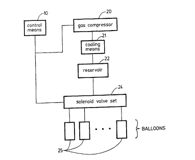
Fig. 1 is a block diagram of a first embodiment of the external
counterpulsation apparatus according to the present invention;
Fig. 2 is a block diagram of a second embodiment of the
external counterpulsation apparatus according to the present invention;
Fig. 3 is a block diagram of a third embodiment of the external
counterpulsation apparatus according to the present invention;
Figs. 4A and 4B are detailed block diagrams of the control
means in the external counterpulsation apparatus according to the present
invention;
Bi
CA 02095690 1998-0~-08
Fig. 4C is a detailed block diagram of the blood pressure and
blood oxygen monitoring means illustrated in Fig. 4B;
Fig. 4D is a schematic diagram showing the relationships
between the variation of cuff pressure, finger pulse wave, and opening and
5 closing of the aortic valve;
Figs. 5A and 5B are partial schematic diagrams of the gas
source portion in the external counterpulsation apparatus according to the
present invention, illustrating gas pipes connected to a semiconductor
cooling device and air conditioning cooling evaporator, respectively;
Fig. 6 is a schematic diagram of the balloon device used in the
external counterpulsation apparatus according to the present invention,
illustrating an improved structure of the balloon cuff body; and
Fig. 7 is a flow chart of the method for controlling the external
counterpulsation apparatus according to the present invention.
15 DETAILED DESCRIPTION OF THE INVENTION (PREFERRED EMBODIMENTS)
A detailed description of the present invention follows with
reference to the accompanying drawings in which like elements are indicated
by like reference numerals.
Fig. 1 is the block diagram of a first embodiment of the external
counterpulsation apparatus according to the present invention, wherein a
control means 10 controls the gas compressor 20 and set of solenoid valves
24. The compressor can be of rotary vane type, piston type, diaphragm or
blower type. However, the preferred embodiment would be a scroll type
compressor as described in the Chinese Patent CN 103081 4A which
essentially consists of two scroll basin with very narrow gaps between
them; with one scroll basin adapted to rotate at a very high speed (3,000
rpm) while the other scroll basin remains stationary. The clenching of the
CA 02095690 1998-0~-08
scroll basins compresses the air radially inwardly toward the center and the
compressed air comes out of the center shaft. The scroll type of
compressor is more efficient in operation, more quiet and smaller in size than
other types of compressors and therefore suitable for the external
s counterpulsation apparatus described herein. During operation, the
compressor 20 operates to produce pressurized gas which is sent into the
positive pressure reservoir 22 via the cooling means 21. A pressure limiting
valve 23is provided on the reservoir 22, which keeps the internal pressure
of the reservoir 22 constant. The opening and closing of the set of solenoid
10 valves 24 is controlled by the inflation and deflation driving signals
generated by the control means in accordance with the heart impedance
blood flow graph of the human body. The set of solenoid valves 24 include
a number of two-position three-way solenoid valves corresponding to the
number of balloons 25. When a valve is in the first of the two positions, it
inflates its balloon, when it is in the second of the two positions, it deflatesits balloon, under control of the control means.
Fig. 2 illustrates a second embodiment of the external
counterpulsation apparatus according to the present invention. In this
embodiment, a control signal is first generated by the control means 10,
then the compressor 20 operates to compress gas into the positive pressure
reservoir 22 after being cooled by the cooling means 21. A pressure limiting
valve 23 is provided on the positive pressure reservoir to keep its internal
pressure constant. A negative pressure reservoir 26 connected to the inlet
of the compressor 20 produces negative pressure. The control means 10
2s controls the opening and closing of the set of solenoid valves 24 by issuinginflating and deflating driving signals in accordance with the results of
detection. Again, when the set of solenoid valves 24 are in the first
B
CA 0209~690 1998-0~-08
19
position, they inflate the balloons 25, when they are in the second position,
they deflate the balloons 25. The gas discharged from the balloons is
discharged into the negative pressure reservoir 26 via the set of solenoid
valves 24, and then returns to the compressor 20. As there may be leakage
s during the circulation of gas, which may affect the amount of gas output
from the compressor, a pressure limiting valve 27 is provided to adjust the
negative pressure in the negative pressure reservoir. When the negative
pressure exceeds a certain value, the pressure limiting valve 27 is opened to
inject a certain amount of gas into the reservoir 26. Fig. 3 illustrates a
10 third embodiment of the external counterpulsation apparatus according to
the present invention, wherein the control means 10 generates control
signals and the compressor 20 operates to produce two portions of
pressurized gas, one portion of pressurized gas is sent to the positive
pressure reservoir 29, while another is sent into the positive pressure
15 reservoir 22 via the cooling means 21 and the throttle valve 28. The
pressure limiting valve 23 is operative to adjust the pressure inside the
reservoir 22. The reference numeral 30 indicates two-position, five-way
solenoid valve or two two-position, three-way solenoid valves, 31 indicates
a mono-directional throttle valve, 35 indicates a cylindrical gas distribution
20 means or cylinder, 37 is a partition and 36 indicates a piston When an
inflation driving signal is issued by the control means, the solenoid valve 30
opens to the first of the two positions, and the gas flow is introduced into
the portion I of the cylinder from the reservoir 29 via the solenoid valve 30
and the throttle governor 31 to push the piston from a first end towards a
25 second end of the cylinder. A space portion lll is formed by the piston and
the cylinder and is always in communication with the reservoir 22, and
vents for the balloons 25 are situated in sequence in the cylinder, the
CA 02095690 1998-0~-08
_
balloons being sequentially inflated as the piston moves towards the second
end of the cylinder. When a deflation signal is issued by the control means,
the solenoid valve 30 is moved to its second position, and the gas in the
reservoir 29 enters the portion 11 of the cylinder via the solenoid valve 30 to
s push the piston back to the first end of the cylinder. At that time, the gas in
portion I is discharged via the solenoid valve 30, and the gas in the balloons
is discharged to the negative pressure reservoir 26. In order to speed
deflation, a solenoid valve 34 is also opened at the same time and the gas
discharged from the balloons is discharged to both negative pressure
10 reservoirs 26 and 33. Negative pressure reservoir 33 is kept at a negative
pressure by the input portion of compressor 32. Discharged gas is also sent
to the reservoir 22 by the output portion of compressor 32.
During the deflation phase, if the pressurized balloon is simply
exhausted into the atmosphere, exhaustion of the balloon may not be
completed, with the residual gas pressing on the tissue mass surrounded by
the balloon cuffs, reducing the much needed vascular space in the body to
receive the volume of blood ejected by the heart. This reduces the ability of
counterpulsation to unload systolic blood pressure and reduces cardiac
workload. The addition of negative pressure reservoirs 26, 33 serves to
effectively and rapidly evacuate the pressurized gas in the balloons at the
onset of systole, thereby ensuring complete absence of pressure on the
lower extremities, enabling the vasculature which has been previously
compressed and emptied during the diastolic period to act as suction to help
the heart to eject blood out and unload the systolic blood pressure. In
addition, and equally important, the addition of the negative pressure
reservoirs 26, 33 ensures the smooth operation of the solenoid valves and
prevents the leakage of large volumes of pressurized gas exhausting into the
B
CA 0209S690 1998-0~-08
atmosphere. This closed gas system reduces the escape of noise generated
by the opening and closing of solenoid valves and movement of air.
Furthermore, during normal operation of external
counterpulsation, there is always some leakage of compressed air from the
s balloon during the inflation period. In order to compensate for the leakage
of air to ensure there is adequate air for the intake of the compressor 20 to
produce air pressure in the range of 5 to 15 psi, a leakage compensation
means such as the use of a vacuum limiting valve, a vacuum pump or
compressor or some combination thereof is provided. An example of the
10 compensation means is a vacuum limiting valve 27 connected to the
negative pressure reservoir 26, set at approximately negative 100 mm Hg.
When the negative pressure reservoir is less than 100 mm Hg, the vacuum
limiting valve is open and air is sucked into the reservoir to provide more air
for the intake of the compressor 20.
Prior art in external counterpulsation make use of bulky, noisy
and power consuming solenoid valves are normally closed to reduce the
generation of heat in keeping them open. However, this situation would
induce danger to the patient in case of power failure if compressed gas is
trapped in the balloons.
This invention provides a gas cylindrical distribution system 35
as shown in Fig. 3, using a syringe system in pushing a piston in one
direction to provide sequential inflation of the balloons, with the balloons 25
(not shown) furthest from the heart being inflated first. The balloons
openings are placed on both sides of the cylinder, connecting to the left and
right limbs as well as buttock. The number of balloons can be 2 to 8 or
more on each side. This is achieve by connecting the balloons furthest from
the heart to the portion of the cylinder closest to the piston, as the piston
B
CA 0209~690 1998-0~-08
'_
36 moves from left to right as shown in Fig. 3. This gas distribution system
uses compressed air to move a piston back and forth along a cylindrical
means, producing a quiet operation without the need of too much power as
compared to the use of bulky, noisy and power consuming solenoid inflation
s and deflation valves, thereby eliminating one of the most noisy part of the
prior art external counterpulsation apparatus, and reducing substantially the
consumption of electric power. More importantly, the solenoid valve 30 is a
normally open valve to portion 11 of the cylinder 35, thereby connecting
portion 11 to the positive pressure reservoir 29 in case of power failure,
10 moving the piston to the left of Fig. 3, exposing all the balloons to the
negative pressure reservoir, thereby deflating all balloons and reducing the
possibility of inducing trauma to the patient.
Figs. 4A and 4B are detailed block diagrams of the control
means in the external counterpulsation apparatus according to the present
15 invention. Using impedance cardiography as the control means in detecting
blood flow in the great arteries, the precise closure of the aortic valves and
the pulse wave generated by external counterpulsation pressure in the
external counterpulsation apparatus according to the present invention,
wherein the reference numeral 1 indicates electrodes. The locations and
20 types of electrodes used are for illustrative purposes and should not be
considered as constraint to such design and configuration.
The detecting electrode 1 consists of five point electrodes
placed in the positions shown in Fig. 4A, that is: electrode A positioned at
the root of the left ear or mastoid, electrode D positioned at the xiphoid
2s process, electrode B positioned at the lift edge of the left sternum below the
clavicle and electrode C positioned at the lift edge of the left sternum
between the forth and fifth rib. Electrodes A and D are both impedance
CA 02095690 1998-0~-08
"_
current electrodes, high frequency constant current being applied to the
body from these two electrodes. Electrodes B and C are both detector
electrodes for measurement of the blood flow impedance signals which may
be derived from blood flow in the great arteries in the thoracic space A
s reference electrode E is positioned in the left anterior of the 10th rib, the
signal obtained between electrodes C and E will be used as the reference
signal for measuring movement of the body, especially motion artifact
produced during the application of external counterpulsation pressure. The
location of the reference electrode E is not important but should be further
10 away from the thoracic space.
Before the start of external counterpulsation treatment, high
frequency constant current is applied to electrodes A an D, and blood flow
impedance signals related to the blood flow in the great arteries in the
thoracic space will be picked up by detector electrodes B and C; these blood
15 flow impedance signals also contain a dip in the waveform indicating the
closure of the aortic valves.
Because of the location of the reference electrodes pair C and
E, the blood flow impedance signals detected between these electrodes will
be much weaker than the signals detected by electrodes B and C. Upon
initiation of external counterpulsation, there will be two additional signals
detected by both pairs of detective electrodes B, C and reference electrodes
C and E, they are the retrograde blood flow impedance signals produced by
the same. The signals from motion artifact will present themselves to both
pairs of electrodes in approximately equal amplitudes, while the signals from
counterpulsation will be larger in the reference electrodes than in the
detector electrodes because of the location of the reference electrodes in
closer proximity to the counterpulsation hemodynamic effects.
B
CA 0209~690 1998-0~-08
24
Consequently, subtraction of reference impedance signals from the detector
impedance signals will provide a fairly clean blood flow impedance signals
from the detector impedance signals will provide a fairly clean blood flow
containing the time of aortic valves closure as well as the retrograde flow
s from counterpulsation. This kind of signal processing is known as self-
adaptive filtering processing. By adjusting the onset of the inflation of the
balloons, the retrograde blood flow signals can be advanced or retreated to
coincide with the aortic valves closure thereby providing optimal
counterpulsation timing. In addition, the adjustment of the optimal timing
10 can also be performed by computer.
A high frequency constant current source 2 consists of: a
transistor oscillator, amplitude limiting amplifier, band-pass filter and voltage-
current convertor to obtain a stable high frequency and stable amplitude
current which is applied to the body by electrode A to measure the
impedance.
An amplifier-filter circuit 3 for the electro-cardiographic signal
consists of: a low-pass differential amplifier and band-pass filter-amplifier,
which amplifies and filters the electrocardiographic signals of the body
obtained from electrodes B and C.
A heart impedance signal amplifier-filter circuit 4 and a
reference impedance signal amplifier-filter circuit 5 for adaptive processing
consist of a band-pass filter-amplifier, a detector, a low-pass filter, and a
differential circuit, signal amplifier-filter circuits amplify and filter the heart
impedance blood flow signals obtained from the electrodes B and C, and the
25 adaptive processed impedance reference signals obtained from the
electrodes C and E.
CA 0209~690 1998-0~-08
A computer system consists of a personal micro-computer 7
and an A/D convertor 6. The A/D convertor converts the
electrocardiographic signals, heart impedance blood flow signals, and
impedance reference signals into digital signals and inputs them into the
s computer. The computer displays the waveform, detects the QRS wave of
the electrocardiogram indicates the upper and lower limits of the pulse rate,
performs adaptive processing of the impedance blood flow signals and the
impedance reference signals, measures the waveform's characteristic points
such as the aortic valves closure and end diastolic and systolic amplitudes,
10 and controls the inflation and deflation time of the external counterpulsation
apparatus through a drive circuit 8.
Fig. 4B is also a detailed block diagram of the control means in
the external counterpulsation apparatus according to the present invention,
wherein the blood-pressure and blood oxygen monitoring means 9 are
15 further added to the basic system shown in Fig. 4A.
Fig. 4C is a schematic block diagram of the blood-pressure and
blood oxygen monitoring means 9 indicated in Fig. 4B.
Fig. 4D is a schematic diagram showing the relationships
between the pressure variation of the cuff, finger pulse wave, and the
20 opening and closing of the aortic valve.
Referring to Fig. 4C, 22 indicates the reservoir of the
counterpulsation apparatus, which inflates a cuff 13 via a pipe, throttle
valve 14, and a passage in a solenoid valve 15. The solenoid valve is a
two-position, three-way valve controlled by the computer 7. The other
2s passage of the solenoid valve is a discharging passage for the cuff, the
discharge speed being controlled by the throttle valve 14. At the beginning
of blood pressure measurement, the inflation passage of the solenoid valve
' B-
CA 0209~690 1998-0~-08
26
15 is opened, the pressurized gas in the reservoir 22 inflates the cuff 13 via
the throttle valve 14 to a predetermined pressure value at which the arteries
are blocked. When they are blocked, a finger pulse transducer 16 is unable
to detect a pulse wave. The inflating passage of the solenoid valve 15 is
s closed and the deflating passage is opened, the gas in the cuff discharges
slowly via the solenoid valve 15 and the throttle valve 14 and the pressure
inside the cuff drops slowly as shown by curve "a" in Fig. 4D. When the
pressure in the cuff is equal to or slightly lower than the maximum arterial
pressure, as shown by curve "b" in Fig. 4D, (systolic pressure before
10 counterpulsation, and diastolic counterpulsation pressure during counter-
pulsation), the blocked blood vessels are pushed open instantaneously. At
that time, the finger pulse transducer 16 will detect a rapidly varying pulse
wave as shown by curve "c" in Fig. 4D. This indicates the arrival of the
maximum pressure of the arteries. The pressure detected by a pressure
transducer 12 at that time is the maximum arterial pressure. Referring to
Fig. 4C, 11 indicates an amplifying processing circuit for the pressure signal,
and 17 indicates an amplifying processing circuit of the pulse signal. The
amplified pressure and the pulse signals are collected and processed by the
computer 7 for performing corresponding counterpulsation control and
20 calculation of oxygen saturation of blood.
It is a physical law that when air is compressed, heat will be
generated. In external counterpulsation, approximately 25 cu. ft. of air is
compressed to 5 to 15 psi pressure, generating a gas with a temperature
reaching as high as 90 - 100 C, depending on the environment and
25 efficiency of the compression means. When compressed gas with such a
high temperature is sent to the balloons which are in close contact with the
patient's skin, it will produce abrasion or burn to the skin, or at the least, an
CA 0209~690 1998-0~-08
uncomfortable feeling to the patient. Therefore, it is essential in this
invention to provide means to cool the compressed air. In general, any
means of cooling can be utilized in this invention, including exposure to the
atmosphere of a long piece of coil of metal pipe connecting the compression
s means to the positive pressure reservoir, use of a fan to fore air to blow
through a coil of metal pipe carrying the heated gas, water cooling such as
that used in the radiator of an automobile, running water cooling, or air
conditioner.
Figs. 5A and 5B are partial schematic diagrams of the gas
10 source portion in the external counterpulsation apparatus according to the
present invention, illustrating the gas pipes connected to a semiconductor
cooling device and an air conditioner cooling evaporator, respectively. 21
and 21' indicate a semiconductor cooling device and an air conditioner
cooling evaporator, respectively, 39 indicates a transmitting pipe, 38
15 indicates fins and 40 indicates heat isolation materials.
Prior art external counterpulsation apparatus utilized materials
such as vinyl, leather, cloth or canvas to make the balloon cuffs. These
cuffs are wrapped tightly around the lower limbs with balloons put in
between the cuffs and the body. When compressed gas is inflated into the
20 balloons, the cuff will also expand and extend outward due to the elasticity
and extensibility of its material, causing significant energy loss since a largeportion of the compressed air serves to deform the cuff. More importantly,
when compressed air is used to expand and extend the cuffs outwardly the
pressure inside the balloons will not be built up quickly, reducing the rate of
25 compression of the tissue mass and the underlying vasculature, causing a
slower external counterpulsation pulse wave moving up the aorta. This
reduces the effectiveness of counterpulsation in increasing the perfusion
~,
CA 0209S690 1998-OS-08
pressure to the coronary arteries and, therefore, the development of
collateral circulations (i.e. a set of new vessels formed in the myocardium
(heart) bypassing the blockages in the coronary arteries). Therefore, the
present invention provides the use of rigid or semi-rigid materials with little
S or no extensibility or elasticity so that the introduction of compressed air
into the balloons will not cause the deformation or expansion of the cuffs,
thereby requiring less pressurized air and reducing energy loss.
Furthermore, the use of rigid or semi-rigid materials in making the cuffs will
result in rapid filling of the balloons, quicker compression of the surrounded
10 tissue mass and therefore a steeper external counterpulsation leading pulse
wave travelling retrogradely up the aorta to the heart.
Fig. 6 is a schematic diagram of the balloon device 41 in the
external counterpulsation apparatus according to the present invention. A
balloon cuff body 44 surrounding the balloon 25 (not shown) is made of
15 materials of certain toughness and hardness such as plastic (e.g.
polyacrylate), aluminum, or other metallic plates, rather than of leather cloth
and canvas, thereby reducing the inflatability and extendibility of the balloon
cuff body can be reduced substantially. Tubular balloon cuff bodies can be
fabricated to fit the upper limbs, lower limbs and other balloon cuff bodies
20 can be fabricated to fit the buttocks, such that the balloon cuff body tightly
surrounds the body without gaps, and is prevented from slipping. Different
sizes of balloon cuffs body should be provided to meet the requirements of
different body shapes. The balloon cuff body 44 can be prefabricated,
preformed or formed out of thermally changeable materials in whatever form
2s is necessary. There are materials of plastic form which become flexible and
can be molded into different shapes when heated to a temperature of 50 to
60 C, and will become rigid and non-distensible when the temperature is
D
CA 0209~690 1998-0~-08
lower, generally to room temperature 20-30 C. Such materials are available
commercially in the United States, such as the Orthoplast used in
orthopaedics.
Generally, any space that exists between the cuff and the
s surrounded body except that occupied by the balloon is known as dead
space. It is essential to reduce this dead space as much as possible so that
the least amount of energy in the form of compressed air is required to
inflate the balloons to the required pressure in the quickest way. This will
reduce the size and energy consumption of the compressor, reduce noise
10 level and therefore reduce the total size of the external counterpulsation
apparatus.
To achieve the object of closely fitting the body and reducing
the dead space, proper paddings 43 can be provided between the balloons
and the balloon cuffs. The paddings may be bags of unformed materials
15 (such as water, powder, fine sand, etc.) or triangular pads made of formed
materials (e.g. rubber), the former could form a pressure bearing surface
which fits the contour of the pressure bearing portion of the body when it
bears pressure; while the latter could meet the needs of patients of various
bodily forms by simply moving the paddings upward or downward to avoid
20 the need to provide balloon cuffs of various sizes. To prevent the skin of a
patient from being chaffed, a result of vibrations producing during
counterpulsation, the edges of the balloon cuff body should be smoothed,
this could be done by slightly turning the edges outwardly, and also could
be done by wrapping the edges with soft materials (e.g. cloth, sponge, etc.).
25 The balloon cuff body could be made from a single piece of material, but for
convenient operation, it is preferable that it be fabricated in separated pieces
B
CA 0209~690 1998-0~-08
which are coupled together with hinges 42 to enable freely opening and
closing.
A balloon cuff body of proper size is selected or fitting paddings
are inserted into the balloon cuff to fit the bodily form of the patient to makes the balloon cuff closely encircle the corresponding portion of the patient.
Fixing belts 45 are then tightened, and counterpulsation can begin.
Fig. 7 is a flow chart of the control method of the external
counterpulsation apparatus according to the present invention, which
comprises the steps of: (a) obtaining an impedance cardiograph and
10 electrocardiographic signals having a clear and stable waveform in the
counterpulsation state by the use of detector electrodes 1, high frequency
constant current source 2, and electrocardiographic and impedance signal
amplifier-filter means 3, 4 and 5, which are collected and displayed by the
computer system 7 (101); (b) the computer system detecting the QRS wave
5 of the electrocardiographic signal (102), performing adaptive processing of
the impedance blood flow signal (103), obtaining the starting point of the
counterpulsation blood flow wave by detecting the impedance cardiograph
after self adaptive filtering processing (104), and calculating the data for
controlling the inflation and deflation time of the counterpulsation apparatus
20 from the interval of the R wave of the electrocardiographic signal and the
starting point of the counterpulsing blood flow wave (105); (c) obtaining an
objective index reflecting the curative effect of counterpulsation by detecting
the peak amplitude of the waveform and duration of the heart systolic wave
and counterpulsing wave in the impedance cardiograph (106); and (d)
25 controlling the inflation and deflation of the external counterpulsation
apparatus by the computer (107). For the safety of the patient during
counterpulsation, the control method of the present invention further
B
CA 0209S690 1998-0~-08
comprises the following steps: (e) detecting the blood pressure state of the
patient with a blood pressure detector means during counterpulsation (108);
(f) detecting the oxygen saturation of the blood of the patient with a blood
oxygen detector during counterpulsation (109). If the detected blood
s pressure value exceeds a predetermined value, or the blood oxygen
saturation goes below a predetermined value, then the computer will direct
the apparatus to stop counterpulsation.
In general, the only serious complications from external
counterpulsation treatment are pulmonary edema and cerebral hemorrhage.
10 Pulmonary edema may arise because of left ventricular (left heart) failure,
and usually can be detected with a rapid drop in the oxygen saturation of
the arterial blood, from a normal value of 95-98% to a value lower than 85-
90%. The monitor of oxygen saturation is an extremely sensitive parameter
of the detection of pulmonary congestion due to left heart failure. The
5 oxygen saturation can be monitored with a pulse oximeter available
commercially and commonly used in any operating room. The use of pulse
oximetry as a noninvasive method to detect the complications of pulmonary
congestion (edema) as well as left heart failure is a novel concept provided
in the present invention. Furthermore, cerebral hemorrhage usually results
from high arterial blood pressure (hypertension). Since an effective external
counterpulsation can raise the peak diastolic pressure to 40 to 60 mm Hg
above systolic blood pressure, it is important not only to measure the resting
blood pressure of the patient before initiation of external counterpulsation
(so that hypertension patients can be treated medically to reduce their blood
pressure before counterpulsation treatment), but it is also important to
monitor the peak arterial blood pressure during treatment to ensure the peak
blood pressure will not rise more than 40 to 50 mm Hg above resting
B
CA 0209~690 1998-0~-08
_,~ J_
systolic pressure. The present invention provides a novel means to monitor the
peak blood pressure effectively. Historically it has been extremely difficult tomeasure blood pressure using any of the presently available measuring methods
during exter"al counterpulsation because of motion artifact as well as the noisy5 environment. The present invention provides a means to accurately determine
the peak blood pressure thereby producing a critical paran,eter in eliminating
such dangerous complications as cerebral hemorrhage.
A closed loop control procedure is performed by the computer and is
as follows: At the beginning of the counterpulsation the computer automatically
10 sets the balloon inflation time to be at the end of the T wave of the
elecl,ocardiograph. Due to the delay before the arrival of the counterpulsing
wave at the aorta the closing point of the aortic valve and the starting point of the
counterpulsing wave can be detected from the heart impedance blood flow graph
by the computer. The computer adjusts the inflation time of the counterpulsation15 apparatus according to the time difference between these two points to move the
starting point of the counterpulsing wave gradually towards the closing point of the
aorta. While gradually matching these two points the computer also calculates
the aorta closing time with the Bazett formula:
TQr = R~/~
20 because of the effect of counterpulsation on the automatic detecting of the closing
point of the aorta. The time QT calculated with the Bazett formula is taken as the
closing time of the aortic valve after the Q wave of the electrocardiograph has
been detected. This makes the starting point of the counterpulsing wave fall into
a range centered at the closing time of the aortic valve. In the procedure of
25 gradually matching the two points the detection of the starting point of the
counterpulsing wave may be affected
,,
CA 0209~690 1998-0~-08
point of the counterpulsing wave may be affected by blood expulsion from
the heart and the variation of blood flow inside the chest. If so, the
computer determines the time delay between the arrival of the
counterpulsing wave at the central region of the aorta and its formation by
s the pressurization of the lower limbs of the patient, by determining the time
difference between the detected starting point of the counterpulsing wave
and the inflation time. The computer adjusts the counterpulsation inflation
time, such that the starting point of the counterpulsation formed after the
time delay falls into a range centered at the closing time of the aortic valve.
10 The computer keeps it in this range during counterpulsation, thereby
performing loop control.
It should be understood that various modifications and
substitutions of conditions of the present invention could be made by those
skilled in the art without departing from the spirit of the present invention,
15 the scope of which is defined by the attached claims.
Bl