Note: Descriptions are shown in the official language in which they were submitted.
209S~97 -` -
~N~E ASSEMBLY FOR CIJTTING A FOOD PRODUCT
' -,
BACK&ROUND OF THE INVENTION
The present invention to a knife blade and a knife blade assembly for
cutting a food product into sticks or slices.
:
Devices for cutting food products into slices or sticks are well-known in
the art and typicalb compnse a stationa~y array of cutting kn ves with a means to
propel the food product through the knife array. The food ~product may be
s ~ conveyed through the knife array by entraining it in a fluid stream, such as water,
or by placing it between opposed conveyors as in U.S. Patent 5,044,240.
~. :: . .
10 ~ Typically the stationary knife array comprises a plurality of knife blades
mounted parallel to each~other. If the food product is to be cut into slices, only a
single such array need be utilized. However, if the food product is to be cut into
stick, such as potatoes for french fries, two such arrays are u with the knives in
.
one array extending generally perpendicular to the knives in the other array. A
is :~ typical knife assembly is disclosed in U.S. Patent 4,766,793.
~,
Although the known knife assemblies have proven generally successful, -
they have not proven successful in cutting certain food products, such as carrots and
:
' ' ' ': ' , ' ., . ' ' ' . ' ,,, , ,' . ,', ' . .: ' . , ' . ,
,. . ,,,, ~ , ~, . ' .' , ' ' ', . ,, . , ' ., ' " '' ' ,, ' ' , ', ,
209~97
brittle potatoes, into sticks or slices. The known knife arrays have caused cracking
of the surfaces of the products, known in ~he industry as "feathering" or
"shattering", which results in an unacceptable product.
The individual knife blades used in the known knife arrays have had
sharp cutting edges, usually formed by beveling one side of the knife blade.
SUMMARY OF THE INVENTION
A knife blade and knife blade assembly are disclosed for cutting food
products into sticks without causing surface cracking of the sticks. The knife blade
has a cutting portion defining a cutting edge and is mounted in the knife assembly
such that a tension force is exerted on the knife blade in the plane of the cutting
edge. The cutting edges of knives in the array are located in a common plane.
. ..
The cutting edge of the knife blade is not sharp, but is generally Rat and
extends between parallel sides of the knife blade.
:
The individual knife blades are formed of stainless steel and are electro-
polished to remove any surface defects or sharp edges which may produce stress
concentrations. This enables a significant tension force to be applied to the @~fe
blade without diminishing its useful life. The electro-polishing pmcess may alsoround off the comers of the juncture between the flat cutting edge and the parallel
knife blade sides.
Through much experimentation with knife-blades having various sizes
~: and cross-sectional configurations, it has been found that the knife blade according
to this invention can reliably cut food products, such as potatoes and carrots into
, ,
sticks without causing cracking of the surface of the sticks.
: ' ....
.
' "''.
. ~ ' ' ', ;, ' ; ' ' ; ~
: ,,":,: '' ' . ' ' , '. , . ,~ . ' . .. .. ' :
` 2~9~X97
' . '
BRIEF DESCRIPTION OF THE DRAVVING~ ~
:
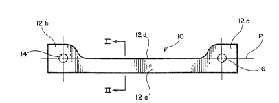
Figure 1 is a side view of a knife blade according to the present
invention.
Figure 2 is a cross-sectional view of the knife blade taken along line II-II
in Figure 1.
Figure 3 is an enlarged view of area A in Figure 2 illustrating the cutting
edge of the knife blade.
Figure 4 is a cross-sectional view, similar to Figure 2, of a knife blade
having a cutting edge with its edges rounded off.
Figure S is an enlarged view of area B in Figure 4 illustrating the
cutting edge.
Figure 6 is a schomatic view of a pair of knife arrays arranged in an
orthogonal pattern so as to cut a food product into sticks. ; ~-
- ..
. ~ , . ,
Figure 7 is a side view of ;a knife assembly according to the present
15 ~ ~ invention having a single knife array.
Figure 8 is a bottom view of the knife assembly of Figure 7.
~ , ,
DETATLED D~SCRlPI~! OF THE PRE~FERRED EMBQDIMEMTS
The knife blade according to the present invention is illustrated at 10 in
Figure 1 and comprises a cutting portion 12a with mounting portions 12b and 12c
20 ~ ~ formed at ather end of the cutting portion. Cutting portion 12a has a cutting edge
, ~
' :., :, '.,, ' , . '' '.. ~, ,': ' , . ' :- ' .' . , . . , ' : . , ' ., . ' . , . : ., : . : .
~ o ~
12d which 16 adapted to accommodate means for attaching the knife blade to a
mounting member, to be hereinafter described in more detail. The centers of
mounting holes 14 and 16 also lie in plane P.
The knife blade of the invention is formed of 301 High Yield stainless
steel. This type of stainless steel has both nickel and chromium, and has a tensile
strength in excess of 300,000 psi. It also has a yield strength that is approximately
equal to its tensile strength.
As illustrated in Figures 2 and 3, the cutting edge 12d is formed as a
generally flat surface extending along plane P. The cutting portion 12a is formed
with opposite parallel sides and may have a thickness t of between O.OOS and 0.015
inch. It has been found that a thickness t of 0.007 to O.ûlO inch gives the mostsatisfactory results.
:. . ..
As noted previously, the knife blade 10 undergoes an electro-polishing -
operation in order to finely polish all of the surfaces to remove any minute cracks
or flaws which may form stress concentration points. The electro-pollshing
operation may also round off the edges where the cutting edge 12d joins the
opposite parallel sides of the cutting portion 12a of the knife blade, as illustrated
in Figures 4 and 5. The electro-polishing operation also rounds off the sharp edges
where holes 14 and 16 pass through the sides of the mounting portions 12b and 12c,
respectively. In order to eliminate knife blade flexing and make straight cuts
through the food product, it has been found that a very high lengthwise tension must
be placed on each of the knife blades. The electro-polishing operation eliminates
all of the stress concentration points on the knife blade to enable the tension to be
- applied without diminishing the operational life of the knife blades.
A plurality of knife blades 10 are arranged as illustrated in Figure 6 in
;~ ~ order to cut the food product into sticks. The arrangement comprises a first array ~;
18 having a plurality of knife blades 10 arranged substantially parallel to each other
and a second knife array 20 with a plurality of knife blades 10 arranged :
"',:
.. .
..
~ - , ~ , , - - ., : .. : . .
209~897
s
substantially parallel to each other. The knives may be located such that the cutting
edges 12d in each array lie in a common plane, or such ~hat the cutting edges 12d
are non coplanar. Depending upon the desired shape of the sticks, the knife blades
in the array 18 may extend generally perpendicular to the knife blades in array 20,
as illustrated, or may extend at oblique angles. The food product is conveyed, by
known means not illustrated, through the arrays of knives in the direction of arrow
22. By applying a tension force on the order of 1000-1200 pounds to each of the
knife blades 10 in the directions of arrows 24 and 26, respectively, in the planes of
the respective cutting edges 12d in conjunction with the blade thickness t and the
cutting edge configuration, it has been found that the food product can be cu~ into
sticks without cracking the surface of the resulting sticks. This has eliminated the
problem of "feathering" or "shattering" that has plagued the food processing
industry. ~- -
Apparatus for mounting the individual knife blades and to apply the
requisite tension thereto is illustrated in Figures 7 and ~. In these figures, a single
knife blade array is illustrated for the purposes of clarity, but it is to be understood
that a second knife blade array, of identical construction, is envisioned with the
knife blades oriented as illustrated in Figure 6.
The apparatus comprises a knife blade array 18 mounted to an attaching
plate 28 which may be attached to a known food product conveying means such thatthe food is conveyed through the knife array 18 in the direction of arrow 22.
Attaching plate 28 defines opening 30 to enable the food product to pass throughthe attaching plate 28 into the knlfe array.
Each knife array may have knife blade mounting meimbers 32 and 34.
As can be seen in Figure 8, the mounting members 32 and 34 have a general "E"-
shaped configuration and each are attached to one end of a plurality of knife blades ;
10. The mounting members 32 and 34 may comprise individual spacers between
each of the knife blades 10 so as to evenly space the knife blades across the opening
30. Mounting members 32 and 34 define openings which are placed in alignment
~; '
, , - -: . , .. : . ~ . . . . . .. . . . . . .. . . .
., : .. ... : ,, ,. , :, .. , ... .. :. :
, , , ,,,, ~ :,, : ,.. ~ '
- , ,., ~. . . ~, " . . . . ..
2~9~97
- 6
with the openings 14 and 16 on the ends of the knife blades. Bolts 36 and 38 rnay
be then passed through the mounting members in each of the indi~1idual knife blades
to attach these elements together.
Mounting member 32 is, in turn, attached to a stationary member 40 by
pin 42 which passes through aligned holes formed in the inter-engaging portions of
the s~ationary member 40 and the mounting member 32. Stationary member 40 is
fixedly attached to side rails 44 and 46 by bolts 48 and 50. Side rails 44 and 46
define holes 52 which may be utilized to attach the second knife array to the first
kni~e array 18 such that its blades extend generally perpendicularly to the blades in
the knife array 18. Mounting member 32 is also fixedly attached to attaching plate
28 via bolts 54 or the like.
Mounting member 34 is attached to the opposite ends of the knife blades
via bolt 38 passing through the holes 16 in the ends of the knife blades and through
a corresponding hole in the mounting member 34. Mounting member 34 is, in
turn, attached to tension member 56 by pin 58 extending through aligned holes inthe interengaging portions of the tension member 56 and mounting member 34.
Bolts 60 threadingly engage tension member 56 and bear against the end of side
rails 44 and 46, respectively. As can be seen, by turning bolts 60, tension member
56 may be caused to move toward the right, as illustrated in Figure 8, away from ;
the stationary member 40 thereby -exerting a tension force on all of the knife blades
in the array. Bolts 62, which pass through the attaching plate 28 and threadingly
engage the mounting member 34, pass through oblong holes 64 defined by the
attaching plate 28 in order to facilitate movement of the mounting member 34 with
respect to the attaching plate 2~. When sufficient tension has been applied to the
knife blades, ~olts 62 may be tightened to assist in holding the mounting member34 in its desired position.
, .. .
Since the centers of holes 14 and 16 lie in the Plane P of the cutting edge
12d, the tension exerted on the knife blades 10 by the tension member 56 will bein the plane o~ the cutting edge.
- ----- . ,- ~ -, , . . . . . ....... ,. . .. . -.. . .. ... . . . .
. ~ . , .. . . , , ;.. : . - , . i . ... . - .
.. . .
,,, , , ; , , ~, ~ ,; .
209~897
As can be seen in Fig. 1, the mounting holes 14 and 16 are circular in
configuration such that substantially all of the tension force applied to opposite ends
of the knife blade 10 is concentrated in the plane P of the cutting edge 12d.
The foregoing description is provided for illustrative purposes only and
S should not be construed as in any way limiting this invention, the scope of which
is defined solely by the appended claims.
.
..
; ~ ' ,'
~ ~ .
: :
' '
.
.,
,; , . -, . ,. , ., ,, ,. . ,~, : ,., .,,: " , ,, . , . : . . . ..
,. . . .
~: - . , ~ , , : - . .