Language selection

Search

Patent 2095906 Summary

Third-party information liability

Some of the information on this Web page has been provided by external sources. The Government of Canada is not responsible for the accuracy, reliability or currency of the information supplied by external sources. Users wishing to rely upon this information should consult directly with the source of the information. Content provided by external sources is not subject to official languages, privacy and accessibility requirements.

Claims and Abstract availability

Any discrepancies in the text and image of the Claims and Abstract are due to differing posting times. Text of the Claims and Abstract are posted:

  • At the time the application is open to public inspection;
  • At the time of issue of the patent (grant).
(12) Patent Application: (11) CA 2095906
(54) English Title: DRILL STRING COMPONENT
(54) French Title: ELEMENT DE TRAIN DE TIGES
Status: Deemed Abandoned and Beyond the Period of Reinstatement - Pending Response to Notice of Disregarded Communication
Bibliographic Data
(51) International Patent Classification (IPC):
  • E21B 17/00 (2006.01)
  • E21B 17/07 (2006.01)
  • E21B 17/18 (2006.01)
(72) Inventors :
  • EKWALL, BERNDT (Sweden)
  • PETERSON, MARTIN (Sweden)
  • ANDERSSON, KURT (Sweden)
(73) Owners :
  • ATLAS COPCO ROCKTECH AB
(71) Applicants :
  • ATLAS COPCO ROCKTECH AB (Sweden)
(74) Agent: SMART & BIGGAR LP
(74) Associate agent:
(45) Issued:
(22) Filed Date: 1993-05-10
(41) Open to Public Inspection: 1993-11-20
Examination requested: 2000-02-25
Availability of licence: N/A
Dedicated to the Public: N/A
(25) Language of filing: English

Patent Cooperation Treaty (PCT): No

(30) Application Priority Data:
Application No. Country/Territory Date
9201562-7 (Sweden) 1992-05-19

Abstracts

English Abstract


Abstract:
Drill string component for use at drilling with a liquid driven down-the-hole
drilling machine (1) comprising three coaxial tubes (2,4,6) for forming channelsfor supply of driving medium to the down-the-hole drilling machine, return of the
driving medium after it has done its work and supply of flushing medium to the
bore hole. The outer ube (2) of the drill string component is provided with a first
end piece (7) which is axially displaceable relative to the outer tube and axially
lockable relative to the outer tube in an outer position so that the inner tubes(4,6) are protected against damage when the drill string component is not
connected with another drill string component, the hammer device (1) or a rotarydevice (9) for rotation of the drill string.
92006.utl


Claims

Note: Claims are shown in the official language in which they were submitted.

Claims:
1. Drill string component for use at drilling with a liquid driven down-
the-hole drilling machine (1) comprising an outer tube (2), an intermediate tube(4) guided in said outer tube by spacers (3), an inner tube (6) guided in said
intermediate tube by spacers (5), whereby said outer tube is provided with a first
(7) and a second (8) end piece at its ends for connection of the drill string
component (20) to other drill string components (30) or to a hammer device (1) or
to a rotary device (9) and the drill string component (20) comprises seals (10,11)
for sealing connection of said intermediate and inner tubes (4,6) to intermediate
and inner tubes (34,36) of an adjacent drill string component (30) or hammer
device (1) or rotary device (9), c h a r a c t e r i z e d in that said first (7) of the
end pieces of the outer tube is connected to the outer tube (2) by means of a
coupling (12) which allows axial displacement of the first end piece (7) relative to
the outer tube (2) between an inner position and an outer position, that the first
end piece and the outer tube in one relative position are nonturnably coupled toeach other and that the first end piece is axially lockable relative to the outer
tube so that either end piece protects the ends of the intermediate and inner
tubes when the first end piece is at said outer position.
2. Drill string component according to claim 1, c h a r a c t e r i z e d
in that said coupling comprises a threaded connection (12) and that the outer
tube (2) is provided with grooves (13) for cooperation with projections (14) on the
first end piece (7) adjacent to its relative to the outer tube inner end, whereby
axial displacement of the first end piece relative to the outer tube results in a
nonturnable coupling between the first end piece and the outer tube.
3. Drill string component according to claim 2, c h a r a c t e r i z e d
in that said first end piece (7) is provided with a thread 19 for connection of the
drill string component to an adjacent drill string component or hammer device
(1) or rotary device (9), whereby displacement of the first end piece (7) in
direction towards said inner position results in a nonturnable coupling between
the first end piece (7) and the outer tube (2) so that the drill string component
92006.utl

6
(20) by means of rotation of said rotary device (9) can be connected to an
adjacent drill string component or hammer device (1) or the rotary device (9) and
after displacement of the first end piece in direction towards said outer position
said threaded connection (12) is tightenable by means of said rotary device.
92006.utl

Description

Note: Descriptions are shown in the official language in which they were submitted.


2095906
Dril]. strin~ component
The present invention relates to a drill string component for use at drilling with
a liquid driven down-the-hole drilling machine.
ln a prior art drill string component of the above mentioned kind,
DE-A-30 1~ 69~, the drill string component is provided with coaxial tubes in
order to form three coaxial channels for conducting driving liquid to and from
the down-the-hole drilling machine and for conducting flushing medium, air or
water, to the drill bit for flushing of the drill hole. A drawback with this solution
is that the two inner tubes which protrude from the outer tube in order to
sealingly cooperate with the corresponding tubes of an adjacent drill string
component easily can be damaged when the drill string component is mounted in
a drill string or when the drill string component is transported. Furthermore, it
is easy to damage the inner tubes when the drill string component is connected
to another drill string component, hammer device or rotary device because one
must first push the inner tubes into the adjacent component and only then screw
the ollter tubes together.
The present invention, which is defined in the subsequent claims, aims at
decreasing the above mentioned problem by arranging it so that the inner tubes
do not protrude from the outer tube when the drill string component is not
mounted in a drill string and arranging it so that the drill string component isguided into the drill string by the thread of the outer tube before the inner tubes
are pushed into the corresponding tubes in the adjacent component in the drill
string.
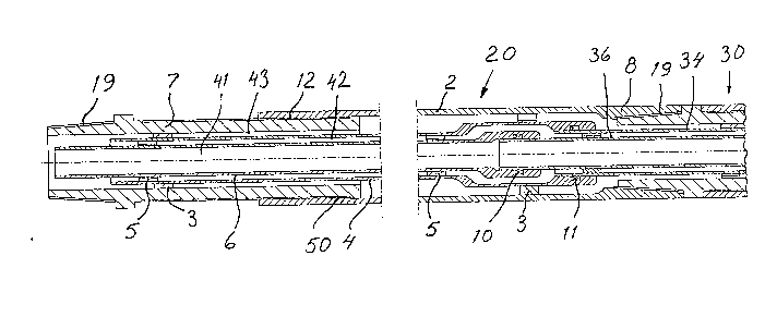
An embodiment of the invention is described below with reference to theaccompnying drawing in which fig 1 shows a drilling device comprising a rotary
device, two drill string components according to the invention and a down-the-
hole drilling machine. Fig 2 shows a longitudinal section through a drill stringcomponent according to the invention and partly through an adjacent drill string
92006.utl

component. Fig 3 shows a detail of~he~de5v91ce according to fig 2. Fig 4 shows the
detail according to fig 3 with the included parts in another relative position.
The drilling device shown in fig 1 comprises a liquid driven down-the-hole
drilling machine 1, two drill string components 20,30 and a rotary device 9 for
rotation of the drill string. The drill string can, of course, contain an arbitrary
number of drill string components.
Drill string component 20 comprises an outer tube 2 in which an intermediate
tube 4 is guided by means of spacers 3. An inner tube 6 is by means of spacers 5guided in the intermediate tube 4. The three tubes define three channels 41, 42
and 43. These can for example be used in the following way. Channel 41 is used
for supply of pressure liquid to the down-the-hole drilling machine 1. Channel 42
is used for transport of liquid after the liquid has done its work in the down-the-
hole drilling machine. Channel 43 is used for supplying flushing medium, air or
water, to the drill bit for flushing the bore hole.Inner tube 6 and intermediatetube 4 are at the right end of figure 2 provided with seals 10 and 11 respectively
for sealing cooperation with inner tube 36 and intermediate tube 34 in the
adjacent drill string component 30. Corresponding cooperation exists also
between rotary device 9 and down-the-hole drilling machine 1 respectively and
the adjacent drill string component.
Outer tube 2 is provided with a first end piece 7 and a second end piece 8. The
first end piece is by means of a threaded connection 12 a~ally movable relat*e
to outer tube 2 between an inner position, shown for drill string component 30,
and an outer position, shown for drill string component 20. By tightening the
threaded connection in either direction axial locking of the first end piece
relative to the outer tube is obtained.Through this end piece 7 will protect inner
tube 6 and intermediate tube 4 when the drill string component is not screwed
into a drill string. First end piece 7 is provided with a thread 19 for connection of
the drill string component with an adjacent drill string component, the rotary
device or the down-the-hole drilling machine. As is shown in figs 3 and 4 first
end piece 7 is provided with projections 14 and the outer tube 2 with grooves 13.
92006.utl

2~9 :3~ 06
These are positioned at about the position marked by the reference numeral 50
in fig 2.As is shown in figs 3 and 4 threaded connection 12 is made such that one
has a certain axial movability between first end piece 7 and outer tube 2. In the
position shown in fig 3 the first end piece is displaced towards its outer position.
In this position the first end piece is turnable relative to the outer tube so that
the threaded connection 12 can be tightened by means of the rotary device 9. In
the position shown in fig 4 first end piece 7 is displaced towards its inner
position. In this position projection 14 is pushed into groove 13 so that the first
end piece and the outer tube are nonturnably coupled to each other so that
thread 19 can be screwed into an adjacent drill string component, the rotary
device or the down-the-hole drilling machine by rotary device 9.
In the shown example tubes 4 and 6 are axially fixed relative to tube 2 so that
the first end piece 7 functions as protection for tubes 4 and 6. It is, of course,
also possible to fix tubes 4 and 6 axially relative to the first end piece 7 so that
the second end piece 8 functions as protection for tubes 4 and 6. It should also be
possible to arrange the tubes such relative to each other that both end pieces
function as protection for the two inner tubes when the drill string component is
not situated in a drill string. In the shown example one has a threaded
connection between the first end piece 7 and outer tube 2. This threaded
connection can be replaced by any guide which allows that the first end piece
and the outer tube in some position are nonturnably coupled with each other so
that the drill string component can be connected with an adjacent drill string
component before the inner tubes are moved into the corresponding tubes of the
adjacent component. The connection of the outer tubes hereby forms a guide for
the moving together of the inner tubes. In addition the first end piece and the
outer tube must be axially lockable relative to each other so that the inner tubes
remain protected when the drill string component is not situated in a drill
string.
The shown device works in the following way when a drill string component is
added to the drill string. The thread 19 arranged at the left end of fig 2 is moved
into an adjacent component. After that the drill string component is pushed to
92006.utl

2~9~906
the left so that the first end piece 7 and the outer tube 2 take the relative
positions shown in fig 4. The first end piece and the outer tube are hereby
nonturnably coupled with each other so that the thread 19 is tightened to the
adjacent component by means of the rotary device 9. The drill string component
is then drawn to the right so that the first end piece 7 and the outer tube 2 take
the relative positions shown in fig 3. Rotation of the rotary device 9 hereby
results in the tightening of threaded connection 12. During this tightening the
two inner tubes are guided into the corresponding tubes of the other component
for sealing cooperation with these tubes.
92006.utl

Representative Drawing
A single figure which represents the drawing illustrating the invention.
Administrative Status

2024-08-01:As part of the Next Generation Patents (NGP) transition, the Canadian Patents Database (CPD) now contains a more detailed Event History, which replicates the Event Log of our new back-office solution.

Please note that "Inactive:" events refers to events no longer in use in our new back-office solution.

For a clearer understanding of the status of the application/patent presented on this page, the site Disclaimer , as well as the definitions for Patent , Event History , Maintenance Fee  and Payment History  should be consulted.

Event History

Description Date
Inactive: IPC from MCD 2006-03-11
Application Not Reinstated by Deadline 2004-12-06
Inactive: Dead - No reply to s.30(2) Rules requisition 2004-12-06
Deemed Abandoned - Failure to Respond to Maintenance Fee Notice 2004-05-10
Inactive: Abandoned - No reply to s.30(2) Rules requisition 2003-12-05
Inactive: S.30(2) Rules - Examiner requisition 2003-06-05
Letter Sent 2000-03-10
Inactive: Status info is complete as of Log entry date 2000-03-10
Inactive: Application prosecuted on TS as of Log entry date 2000-03-10
Request for Examination Requirements Determined Compliant 2000-02-25
All Requirements for Examination Determined Compliant 2000-02-25
Application Published (Open to Public Inspection) 1993-11-20

Abandonment History

Abandonment Date Reason Reinstatement Date
2004-05-10

Maintenance Fee

The last payment was received on 2003-04-07

Note : If the full payment has not been received on or before the date indicated, a further fee may be required which may be one of the following

  • the reinstatement fee;
  • the late payment fee; or
  • additional fee to reverse deemed expiry.

Patent fees are adjusted on the 1st of January every year. The amounts above are the current amounts if received by December 31 of the current year.
Please refer to the CIPO Patent Fees web page to see all current fee amounts.

Fee History

Fee Type Anniversary Year Due Date Paid Date
MF (application, 5th anniv.) - standard 05 1998-05-11 1998-04-28
MF (application, 6th anniv.) - standard 06 1999-05-10 1999-04-15
Request for examination - standard 2000-02-25
MF (application, 7th anniv.) - standard 07 2000-05-10 2000-04-18
MF (application, 8th anniv.) - standard 08 2001-05-10 2001-04-05
MF (application, 9th anniv.) - standard 09 2002-05-10 2002-04-10
MF (application, 10th anniv.) - standard 10 2003-05-12 2003-04-07
Owners on Record

Note: Records showing the ownership history in alphabetical order.

Current Owners on Record
ATLAS COPCO ROCKTECH AB
Past Owners on Record
BERNDT EKWALL
KURT ANDERSSON
MARTIN PETERSON
Past Owners that do not appear in the "Owners on Record" listing will appear in other documentation within the application.
Documents

To view selected files, please enter reCAPTCHA code :


To view images, click a link in the Document Description column. To download the documents, select one or more checkboxes in the first column and then click the "Download Selected in PDF format (Zip Archive)" or the "Download Selected as Single PDF" button.

List of published and non-published patent-specific documents on the CPD .

If you have any difficulty accessing content, you can call the Client Service Centre at 1-866-997-1936 or send them an e-mail at CIPO Client Service Centre.


Document
Description 
Date
(yyyy-mm-dd) 
Number of pages   Size of Image (KB) 
Representative drawing 1999-02-21 1 22
Abstract 1994-03-04 1 18
Claims 1994-03-04 2 58
Drawings 1994-03-04 1 36
Description 1994-03-04 4 162
Reminder - Request for Examination 2000-01-10 1 119
Acknowledgement of Request for Examination 2000-03-09 1 178
Courtesy - Abandonment Letter (R30(2)) 2004-02-15 1 168
Courtesy - Abandonment Letter (Maintenance Fee) 2004-07-04 1 175
Fees 1997-04-23 1 80
Fees 1995-04-25 1 75
Fees 1996-04-22 1 83