Sélection de la langue

Search

Sommaire du brevet 2095906 

Énoncé de désistement de responsabilité concernant l'information provenant de tiers

Une partie des informations de ce site Web a été fournie par des sources externes. Le gouvernement du Canada n'assume aucune responsabilité concernant la précision, l'actualité ou la fiabilité des informations fournies par les sources externes. Les utilisateurs qui désirent employer cette information devraient consulter directement la source des informations. Le contenu fourni par les sources externes n'est pas assujetti aux exigences sur les langues officielles, la protection des renseignements personnels et l'accessibilité.

Disponibilité de l'Abrégé et des Revendications

L'apparition de différences dans le texte et l'image des Revendications et de l'Abrégé dépend du moment auquel le document est publié. Les textes des Revendications et de l'Abrégé sont affichés :

  • lorsque la demande peut être examinée par le public;
  • lorsque le brevet est émis (délivrance).
(12) Demande de brevet: (11) CA 2095906
(54) Titre français: ELEMENT DE TRAIN DE TIGES
(54) Titre anglais: DRILL STRING COMPONENT
Statut: Réputée abandonnée et au-delà du délai pour le rétablissement - en attente de la réponse à l’avis de communication rejetée
Données bibliographiques
(51) Classification internationale des brevets (CIB):
  • E21B 17/00 (2006.01)
  • E21B 17/07 (2006.01)
  • E21B 17/18 (2006.01)
(72) Inventeurs :
  • EKWALL, BERNDT (Suède)
  • PETERSON, MARTIN (Suède)
  • ANDERSSON, KURT (Suède)
(73) Titulaires :
  • ATLAS COPCO ROCKTECH AB
(71) Demandeurs :
  • ATLAS COPCO ROCKTECH AB (Suède)
(74) Agent: SMART & BIGGAR LP
(74) Co-agent:
(45) Délivré:
(22) Date de dépôt: 1993-05-10
(41) Mise à la disponibilité du public: 1993-11-20
Requête d'examen: 2000-02-25
Licence disponible: S.O.
Cédé au domaine public: S.O.
(25) Langue des documents déposés: Anglais

Traité de coopération en matière de brevets (PCT): Non

(30) Données de priorité de la demande:
Numéro de la demande Pays / territoire Date
9201562-7 (Suède) 1992-05-19

Abrégés

Abrégé anglais


Abstract:
Drill string component for use at drilling with a liquid driven down-the-hole
drilling machine (1) comprising three coaxial tubes (2,4,6) for forming channelsfor supply of driving medium to the down-the-hole drilling machine, return of the
driving medium after it has done its work and supply of flushing medium to the
bore hole. The outer ube (2) of the drill string component is provided with a first
end piece (7) which is axially displaceable relative to the outer tube and axially
lockable relative to the outer tube in an outer position so that the inner tubes(4,6) are protected against damage when the drill string component is not
connected with another drill string component, the hammer device (1) or a rotarydevice (9) for rotation of the drill string.
92006.utl

Revendications

Note : Les revendications sont présentées dans la langue officielle dans laquelle elles ont été soumises.


Claims:
1. Drill string component for use at drilling with a liquid driven down-
the-hole drilling machine (1) comprising an outer tube (2), an intermediate tube(4) guided in said outer tube by spacers (3), an inner tube (6) guided in said
intermediate tube by spacers (5), whereby said outer tube is provided with a first
(7) and a second (8) end piece at its ends for connection of the drill string
component (20) to other drill string components (30) or to a hammer device (1) or
to a rotary device (9) and the drill string component (20) comprises seals (10,11)
for sealing connection of said intermediate and inner tubes (4,6) to intermediate
and inner tubes (34,36) of an adjacent drill string component (30) or hammer
device (1) or rotary device (9), c h a r a c t e r i z e d in that said first (7) of the
end pieces of the outer tube is connected to the outer tube (2) by means of a
coupling (12) which allows axial displacement of the first end piece (7) relative to
the outer tube (2) between an inner position and an outer position, that the first
end piece and the outer tube in one relative position are nonturnably coupled toeach other and that the first end piece is axially lockable relative to the outer
tube so that either end piece protects the ends of the intermediate and inner
tubes when the first end piece is at said outer position.
2. Drill string component according to claim 1, c h a r a c t e r i z e d
in that said coupling comprises a threaded connection (12) and that the outer
tube (2) is provided with grooves (13) for cooperation with projections (14) on the
first end piece (7) adjacent to its relative to the outer tube inner end, whereby
axial displacement of the first end piece relative to the outer tube results in a
nonturnable coupling between the first end piece and the outer tube.
3. Drill string component according to claim 2, c h a r a c t e r i z e d
in that said first end piece (7) is provided with a thread 19 for connection of the
drill string component to an adjacent drill string component or hammer device
(1) or rotary device (9), whereby displacement of the first end piece (7) in
direction towards said inner position results in a nonturnable coupling between
the first end piece (7) and the outer tube (2) so that the drill string component
92006.utl

6
(20) by means of rotation of said rotary device (9) can be connected to an
adjacent drill string component or hammer device (1) or the rotary device (9) and
after displacement of the first end piece in direction towards said outer position
said threaded connection (12) is tightenable by means of said rotary device.
92006.utl

Description

Note : Les descriptions sont présentées dans la langue officielle dans laquelle elles ont été soumises.

2095906
Dril]. strin~ component
The present invention relates to a drill string component for use at drilling with
a liquid driven down-the-hole drilling machine.
ln a prior art drill string component of the above mentioned kind,
DE-A-30 1~ 69~, the drill string component is provided with coaxial tubes in
order to form three coaxial channels for conducting driving liquid to and from
the down-the-hole drilling machine and for conducting flushing medium, air or
water, to the drill bit for flushing of the drill hole. A drawback with this solution
is that the two inner tubes which protrude from the outer tube in order to
sealingly cooperate with the corresponding tubes of an adjacent drill string
component easily can be damaged when the drill string component is mounted in
a drill string or when the drill string component is transported. Furthermore, it
is easy to damage the inner tubes when the drill string component is connected
to another drill string component, hammer device or rotary device because one
must first push the inner tubes into the adjacent component and only then screw
the ollter tubes together.
The present invention, which is defined in the subsequent claims, aims at
decreasing the above mentioned problem by arranging it so that the inner tubes
do not protrude from the outer tube when the drill string component is not
mounted in a drill string and arranging it so that the drill string component isguided into the drill string by the thread of the outer tube before the inner tubes
are pushed into the corresponding tubes in the adjacent component in the drill
string.
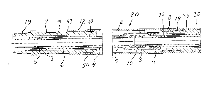
An embodiment of the invention is described below with reference to theaccompnying drawing in which fig 1 shows a drilling device comprising a rotary
device, two drill string components according to the invention and a down-the-
hole drilling machine. Fig 2 shows a longitudinal section through a drill stringcomponent according to the invention and partly through an adjacent drill string
92006.utl

component. Fig 3 shows a detail of~he~de5v91ce according to fig 2. Fig 4 shows the
detail according to fig 3 with the included parts in another relative position.
The drilling device shown in fig 1 comprises a liquid driven down-the-hole
drilling machine 1, two drill string components 20,30 and a rotary device 9 for
rotation of the drill string. The drill string can, of course, contain an arbitrary
number of drill string components.
Drill string component 20 comprises an outer tube 2 in which an intermediate
tube 4 is guided by means of spacers 3. An inner tube 6 is by means of spacers 5guided in the intermediate tube 4. The three tubes define three channels 41, 42
and 43. These can for example be used in the following way. Channel 41 is used
for supply of pressure liquid to the down-the-hole drilling machine 1. Channel 42
is used for transport of liquid after the liquid has done its work in the down-the-
hole drilling machine. Channel 43 is used for supplying flushing medium, air or
water, to the drill bit for flushing the bore hole.Inner tube 6 and intermediatetube 4 are at the right end of figure 2 provided with seals 10 and 11 respectively
for sealing cooperation with inner tube 36 and intermediate tube 34 in the
adjacent drill string component 30. Corresponding cooperation exists also
between rotary device 9 and down-the-hole drilling machine 1 respectively and
the adjacent drill string component.
Outer tube 2 is provided with a first end piece 7 and a second end piece 8. The
first end piece is by means of a threaded connection 12 a~ally movable relat*e
to outer tube 2 between an inner position, shown for drill string component 30,
and an outer position, shown for drill string component 20. By tightening the
threaded connection in either direction axial locking of the first end piece
relative to the outer tube is obtained.Through this end piece 7 will protect inner
tube 6 and intermediate tube 4 when the drill string component is not screwed
into a drill string. First end piece 7 is provided with a thread 19 for connection of
the drill string component with an adjacent drill string component, the rotary
device or the down-the-hole drilling machine. As is shown in figs 3 and 4 first
end piece 7 is provided with projections 14 and the outer tube 2 with grooves 13.
92006.utl

2~9 :3~ 06
These are positioned at about the position marked by the reference numeral 50
in fig 2.As is shown in figs 3 and 4 threaded connection 12 is made such that one
has a certain axial movability between first end piece 7 and outer tube 2. In the
position shown in fig 3 the first end piece is displaced towards its outer position.
In this position the first end piece is turnable relative to the outer tube so that
the threaded connection 12 can be tightened by means of the rotary device 9. In
the position shown in fig 4 first end piece 7 is displaced towards its inner
position. In this position projection 14 is pushed into groove 13 so that the first
end piece and the outer tube are nonturnably coupled to each other so that
thread 19 can be screwed into an adjacent drill string component, the rotary
device or the down-the-hole drilling machine by rotary device 9.
In the shown example tubes 4 and 6 are axially fixed relative to tube 2 so that
the first end piece 7 functions as protection for tubes 4 and 6. It is, of course,
also possible to fix tubes 4 and 6 axially relative to the first end piece 7 so that
the second end piece 8 functions as protection for tubes 4 and 6. It should also be
possible to arrange the tubes such relative to each other that both end pieces
function as protection for the two inner tubes when the drill string component is
not situated in a drill string. In the shown example one has a threaded
connection between the first end piece 7 and outer tube 2. This threaded
connection can be replaced by any guide which allows that the first end piece
and the outer tube in some position are nonturnably coupled with each other so
that the drill string component can be connected with an adjacent drill string
component before the inner tubes are moved into the corresponding tubes of the
adjacent component. The connection of the outer tubes hereby forms a guide for
the moving together of the inner tubes. In addition the first end piece and the
outer tube must be axially lockable relative to each other so that the inner tubes
remain protected when the drill string component is not situated in a drill
string.
The shown device works in the following way when a drill string component is
added to the drill string. The thread 19 arranged at the left end of fig 2 is moved
into an adjacent component. After that the drill string component is pushed to
92006.utl

2~9~906
the left so that the first end piece 7 and the outer tube 2 take the relative
positions shown in fig 4. The first end piece and the outer tube are hereby
nonturnably coupled with each other so that the thread 19 is tightened to the
adjacent component by means of the rotary device 9. The drill string component
is then drawn to the right so that the first end piece 7 and the outer tube 2 take
the relative positions shown in fig 3. Rotation of the rotary device 9 hereby
results in the tightening of threaded connection 12. During this tightening the
two inner tubes are guided into the corresponding tubes of the other component
for sealing cooperation with these tubes.
92006.utl

Dessin représentatif
Une figure unique qui représente un dessin illustrant l'invention.
États administratifs

2024-08-01 : Dans le cadre de la transition vers les Brevets de nouvelle génération (BNG), la base de données sur les brevets canadiens (BDBC) contient désormais un Historique d'événement plus détaillé, qui reproduit le Journal des événements de notre nouvelle solution interne.

Veuillez noter que les événements débutant par « Inactive : » se réfèrent à des événements qui ne sont plus utilisés dans notre nouvelle solution interne.

Pour une meilleure compréhension de l'état de la demande ou brevet qui figure sur cette page, la rubrique Mise en garde , et les descriptions de Brevet , Historique d'événement , Taxes périodiques et Historique des paiements devraient être consultées.

Historique d'événement

Description Date
Inactive : CIB de MCD 2006-03-11
Demande non rétablie avant l'échéance 2004-12-06
Inactive : Morte - Aucune rép. dem. par.30(2) Règles 2004-12-06
Réputée abandonnée - omission de répondre à un avis sur les taxes pour le maintien en état 2004-05-10
Inactive : Abandon. - Aucune rép dem par.30(2) Règles 2003-12-05
Inactive : Dem. de l'examinateur par.30(2) Règles 2003-06-05
Lettre envoyée 2000-03-10
Inactive : Renseign. sur l'état - Complets dès date d'ent. journ. 2000-03-10
Inactive : Dem. traitée sur TS dès date d'ent. journal 2000-03-10
Exigences pour une requête d'examen - jugée conforme 2000-02-25
Toutes les exigences pour l'examen - jugée conforme 2000-02-25
Demande publiée (accessible au public) 1993-11-20

Historique d'abandonnement

Date d'abandonnement Raison Date de rétablissement
2004-05-10

Taxes périodiques

Le dernier paiement a été reçu le 2003-04-07

Avis : Si le paiement en totalité n'a pas été reçu au plus tard à la date indiquée, une taxe supplémentaire peut être imposée, soit une des taxes suivantes :

  • taxe de rétablissement ;
  • taxe pour paiement en souffrance ; ou
  • taxe additionnelle pour le renversement d'une péremption réputée.

Les taxes sur les brevets sont ajustées au 1er janvier de chaque année. Les montants ci-dessus sont les montants actuels s'ils sont reçus au plus tard le 31 décembre de l'année en cours.
Veuillez vous référer à la page web des taxes sur les brevets de l'OPIC pour voir tous les montants actuels des taxes.

Historique des taxes

Type de taxes Anniversaire Échéance Date payée
TM (demande, 5e anniv.) - générale 05 1998-05-11 1998-04-28
TM (demande, 6e anniv.) - générale 06 1999-05-10 1999-04-15
Requête d'examen - générale 2000-02-25
TM (demande, 7e anniv.) - générale 07 2000-05-10 2000-04-18
TM (demande, 8e anniv.) - générale 08 2001-05-10 2001-04-05
TM (demande, 9e anniv.) - générale 09 2002-05-10 2002-04-10
TM (demande, 10e anniv.) - générale 10 2003-05-12 2003-04-07
Titulaires au dossier

Les titulaires actuels et antérieures au dossier sont affichés en ordre alphabétique.

Titulaires actuels au dossier
ATLAS COPCO ROCKTECH AB
Titulaires antérieures au dossier
BERNDT EKWALL
KURT ANDERSSON
MARTIN PETERSON
Les propriétaires antérieurs qui ne figurent pas dans la liste des « Propriétaires au dossier » apparaîtront dans d'autres documents au dossier.
Documents

Pour visionner les fichiers sélectionnés, entrer le code reCAPTCHA :


Pour visualiser une image, cliquer sur un lien dans la colonne description du document. Pour télécharger l'image (les images), cliquer l'une ou plusieurs cases à cocher dans la première colonne et ensuite cliquer sur le bouton "Télécharger sélection en format PDF (archive Zip)" ou le bouton "Télécharger sélection (en un fichier PDF fusionné)".

Liste des documents de brevet publiés et non publiés sur la BDBC .

Si vous avez des difficultés à accéder au contenu, veuillez communiquer avec le Centre de services à la clientèle au 1-866-997-1936, ou envoyer un courriel au Centre de service à la clientèle de l'OPIC.


Description du
Document 
Date
(aaaa-mm-jj) 
Nombre de pages   Taille de l'image (Ko) 
Dessin représentatif 1999-02-21 1 22
Abrégé 1994-03-04 1 18
Revendications 1994-03-04 2 58
Dessins 1994-03-04 1 36
Description 1994-03-04 4 162
Rappel - requête d'examen 2000-01-10 1 119
Accusé de réception de la requête d'examen 2000-03-09 1 178
Courtoisie - Lettre d'abandon (R30(2)) 2004-02-15 1 168
Courtoisie - Lettre d'abandon (taxe de maintien en état) 2004-07-04 1 175
Taxes 1997-04-23 1 80
Taxes 1995-04-25 1 75
Taxes 1996-04-22 1 83