Note: Descriptions are shown in the official language in which they were submitted.
~oooo~~
Process for Manufacturing Reinforced Duroplastic Pipes in a
Centrifugal Process and Tnstallation for Carrying Out tine
Process
DESCRIPTION
There exists a prior art installation for manufacturing
reinforced duroplastio pipes, that is, pipes made of a resin,
to which a filler may be added, the appropriate catalyst, as
well as glass fibre inserts and a sand in a centrifugal pro-
eess. This prior art installation has an injection carriage
provided with a feed arm and is suspended, in the manner of a
stock crane, on a vertically displaceable frame, i.e. on two
tracks disposed one on each column, and contains all the
starting materials, except the liquid resin, for feeding the
rotating, cylindrical mould, namely 1 1/2 to 3 m3 sand, the
~;l
glass fibres and the liquid catalys t. To refill the sand the
carriage must be brought to a special loading point and filled
there, which always pauses a considerable interruption in the
operation. To supply the electrical energy required to drive
the travel mechanism, the liquid pumps, the feed devise for
the sand, the cutting device fox the glass fibres, and to feed
the latter into the interior of the mould, towed cables, which
are expensive to install and maintain, but which cannot be
replaced by anything less expensive, are used for eadh of the
two displacement devices.
When a pipe is manufactured, the individual components which
go to make up the pipe, that is, the liquid resin, which may
contain a fine filler, the corresponding catalyst, the glass
fibres and the sand, are introduced from the outlet at the
free end of the feed arm into a rotating, drum-shaped mould
and the appropriate mould speed, injection carriage advance-
ment rate and quantity of individual components conveyed are
CA 02096015 1999-09-20
._
~ 24610-17
r-A
selected according to the required composition. During careful
quality checking of the pipes manufactured with these prior art
installations, small fluctuations in the uniformity of the
composition of the wall were noted, consisting essentially of
an irregularity in the distribution of the sand, both as
regards the thickness and the graining. Although these
fluctuations lie below a tolerance level and are therefore
harmless, they ought to be avoided to improve quality.
However, since they could not be systematically reproduced, it
was not possible to establish the cause and to eliminate them.
Detailed studies and intermediate measurements revealed that
the fluctuations in the regularity of the sand granulation,
that is the accumulation of course grained sand at certain
points and of fine grained sand at other points are probably
caused by the sand separating out in the sand container due to
the vibration of the container, and that the cause of the
irregularities in the distribution of the sand might be due to
the fact that the height of the feed arm outlet of the
injection carriage is not constant.
These disadvantages are now to be overcome with this
invention. This is made possible on the one hand by a new
process which is characterized in that the sand is fed
continuously from a fixed bin to an intermediate container
disposed in the injection carriage and is then introduced from
there into the mould according to the production program preset
to the required pipe composition.
Although the basic ideas from the prior art
installation were adopted in the installation according to this
invention, they are implemented in a significantly more
advantageous manner, so that in addition to the intended
improvement in quality, it was also possible to achieve a
reduction in the set-up and maintenance costs of the
installation and also, due to the much shorter down-times, a
considerably higher production rate.
CA 02096015 1999-09-20
,,i-.
- 3 -
SU~~ARY OF THE INVENTION
This invention seeks to provide a process for
producing a composite pipe, this process comprising the steps
of: providing a pipe mold; providing a movable injection
carriage with a working bin; providing a stationary bin;
moving filler from said stationary bin to said working bin to
maintain a level of filler in the working bin substantially
constant; moving said injection carriage in an injection
direction into and out of said mold; feeding said filler from
said working bin into said mold when said injection carriage
is in said mold.
This invention also seeks to provide an apparatus
for producing a plurality of composite pipes, this apparatus
comprising: a plurality of pipe molds; an injection carriage
movable in a mold direction from one of said plurality of
molds to another, said injection carriage including a working
bin and a feed arm means movable in an injection direction
into and out of each of said molds and for feeding filler from
said working bin into said each of said molds; a stationary
bin with respect to said injection carriage and spaced from
said injection carriage; flexible filler delivery means for
moving filler from said stationary bin to said working bin,
independent of a position of said injection carriage in said
mold direction; control means for controlling said filler
delivery means to maintain an amount of filler in said working
bin below a volume that would cause separation of the filler
in said working bin, said control means also maintaining said
amount of filler in said working bin sufficiently constant
during each of said feedings of filler into each of said molds
to substantially identically distribute the filler in each of
said molds.
An embodiment of the invention will be described
below with reference to the accompanying drawings, in which:
Figure 1 shows a purely diagrammatic top-plan view
of an installation according to the invention with four moulds
and one injection carriage,
Figure 2 shows the same view, with the injection
carriage in a different position,
CA 02096015 1999-09-20
- 4 -
Figure 3 is a side elevation of the installation,
Figure 4 is a side elevation of the injection
carriage on a larger scale.
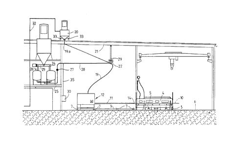
The installation illustrated in Figures 1 to 3 has
four centrifugal drums 1, 2, 3, and 4 for manufacturing
plastic pipes. Even though in the drawings, these drums all
have the same diameter it is certainly possible to dispose
centrifugal drums with varying diameters adjacent to one
another. These centrifugal drums are rotatably mounted on
purely diagramm-
r..
~C~~~!~~
- 5 -
atically illustrated bearings 5. Motors, (not shown), serve
to rotate these drums at the required number of revolutions.
As can be seen in Figure 3, the bearings 5 stand on the floor
6 of the production hall. On this same floor 6, or contrived
therein, two or more tracks ? are also disposed for the
wheels, tnot shown in the drawing), of the chassis 9, The
chassis 9, which is provided with motor-driven wheels, is
thereby displaceable in a direction transverse to the dir-
ection of the drum axis 10. Standing on this chassis 9 is the
injection carriage, which is provided with a feed arm 11, and
is designated as a whole by 12. Also by means of motor-driven
wheels, the latter is displaceable on the chassis 9 in its
longitudinal direction, that is, in the direction of the drum
axis 10. As can be seen in Fig. 4, it contains a small, i.e.
comprising 150 to 500 litres, working bin 13 serving as an
intermediate container for the sand, as well as a feed screw
15, (represented in the drawing by two straight lines only),
provided with a variable revolution motor, designed as a
dosing device and extending up to the free end 14 of the feed
arm 11, for conveying the sand from the working bin 13 to the
outlet 14a of arm 11. Furthermore, the carriage contains two
catalyst bins 1b and 1?, each provided with a dosing pump, as
well as the reels of glass fibre 18. In the free end 14 of
the feed arm there is a device provided with rotating cutting
knives to draw the glass fibre thread more or less quickly, as
needed, to the free end to cut it there into pieces of the
required length. Because the chassis 9 stands on the floor,
where it is displaceable on two or three or even four tracks,
it is preventing from bending downwards in the middle.
Because the injection carriage is significantly lighter, due
to the smaller sand bin, than in the previous prior art
installation, the risk of bending is much less than in the
prior art installations, even if only two tracks ? are used.
If the chassis 9 were to bend, it would not only cause the
height of the free end 14 of the feed arm 11 with the outlet
- 6 -
14a to change when the injection carriage 12 is displaced on
its chassis 9, it would also mean that this change would
depend on the momentary content level, i.e. the weight of the
injection carriage. Once it had been realized that certain
irregularities were caused by these unperiodiaal changes, they
were able to be completely eliminated by 'the new arrangement. '
A further step, namely the essential one, in avoiding
sporadically oaaurring deviations in precision was achieved
due to the fast that in the installation of the invention, the
injection carriage 12 oontains only one intermediate container
for the sand, namely the relatively small working bin 13, that
is, a bin with a volume of 150 to 500 litres, and due to the
fact that the latter is connected via a flexible line 19 with
a bulk bin 20 fixed on a higher storey, in this case on the
ceiling 21, from which the sand is conveyed continuously into
the working bin 13 by means of compressed air. The transport
air can flow back to the bulk bin via a flexible line disposed
parallel to flexible line 19. Because the sand now remains
for only a short time in the working bin serving as the
intermediate container it does not separate out, and this was
determined by an examination of the finished product.
The bulk bin 20 is itself provided with a conveying device
which is merely diagrammatically represented in Fig. 3 as line
32 and which may be any sand conveying device known per se,
for example, a conveyor belt or a conveying device driven by
compressed air or a differently designed device. Both the
bulk bin 20 and the working bin 13 are fitted with weight
measurement cells, the first being designated by 33 and the
others by 34. 30 designates a calculating and control appar-
atus which switches on the aforementioned conveying device 32
for filling the bulk bin 20 when an adjustable minimum weight
or volume is reached, and switches it off when an adjustable
maximum weight or volume is reached, but blocks it for the
Cro o ~1 r i ~ y ~t ('~
!, ~ ~; . r i 1 i i j.. V
time during which sand is introduced into one of the rotating
moulds by means of the feed screw 15. This calculating and
control apparatus also serves to control the rate of advance-
ment of the injection carriage 12 according to a preset
program, said program being of course designed for manufac-
turing a pipe with a quite definite layer composition.
Furthermore, the calculating and control apparatus serves to
measure continously the weights of the bulk bin and the
working bin and add the two weights and measure the reduction
of this total weight whenever sand is introduced into the
mould and then to control, accarding to the preset program,
the conveying and dosing installation, that is, in this case,
the feed screw 15 whenever sand is delivered so that the
specific quantity delivered, that is, the quantity delivered
per unit of time, and also the duration of the individual sand
feed operation run according to the preset program.
The following advantages result from the process of the
invention and the arrangement of the invention:
1. The sand is prevented from separating out by being conveyed
and stared in such a way that there is no longer any
possibility of a separation, thus guaranteeing a perfectly
homogenous distribution of sand in the finished product.
2. Since the injection carriage can only contain maximum 500
litres sand it is significantly lighter than an injection
carriage containing 1 1/2 or even up to 3 m' of sand.
Thus, much less energy is required to advance the carriage
and to brake it.
3. Since, due to the constant supply of sand, the weight of
the injection carriage varies only insignificantly, the
change in speed at the beginning and the end of each
displacement movement can be controlled so that it may be
_8_
exactly reproduced, which gives greater accuracy and
uniformity in the distribution of all components and thus
in the pipe manufacturing process.
4. The down-times previously required to fill up the bin
housed in the injection carriage no longer occur since it
can be refilled at any time from the bulk bin 20,
regardless of whatever operating condition the injection
carriage 12 is in.
All these advantages, by means of which a qualitatively
significantly improved product can be manufactured in
comparison with the manufacturing processes of the old
installations, are certainly, with hindsight, clear and
obvious although it was almost impossible to determine the
cause for the sporadically occurring irregularities in the
pipes manufactured with the prior art processes and
installations.
As can be seen in Fag. 3, the flexible line 19 is affixed to
a support 22 which, in this case, i$ a runner mechanism
suspended on a horizontal runner rail 29 suspended from the
ceiling 21 at a distance thereto. As can be seen in Figures 1
and 2, the runner rail ~29 is circularly curved in such a way
that its centre 29a lies below the point 19a at which the
flexible line 19 leaves the hulk bin 20. Furthermore, it is
disposed so that. the middle of the rail 29b lies in the area
above the centre between two extreme positions of the
injection carriage 12. Naturally, the definitive design of
the support 22 could be slightly different. As can be seen in
Figures 1 and 2, the support 22 can easily be displaced in
this manner to allow continuous feeding of the working bin 13
in injection carriage 12, regardless whether the injection
carriage is in an extreme position, as shown in Figure 1, or
in a more central position, as shown in Figure 2.
~~~~i~~.5
In Figure 3 of the drawings it can furthermore be seen that
a tank or a tank installation 26 for the liquid resin is
housed in a space 24, wflexible floor 25 is located abave the
floor 6 of the building. This installation may, as can be
seen in Figure 3, additionally contain a mixing station 29, by
means of which fine additives such as calcium carbonate can be
added to the liquid resin. An electrically driven conveying
and dosing pump 2? connected to the calculating and control
apparatus 30 conveys 'the liquid resin through a second flex-
ible line 28 to the injection carriage 22. This second
flexible line is also affixed to the support 22 and from there
accompanies the first flexible line 19 to the injection
carriage 12, where additional control elements 31 control the
flow to the outlet 14. Because the liquid resin supply bins
are not housed in the injection carriage it is possible, by
means of a simple valve operation, to modify the liquid resin
or to use a different liquid resin, thereby avoiding further
shutdown time.
Together with the two flexible lines 19 and 28 and the
reflex line for the air serving to transport the sand, the
control lines 32 from the calculating and control apparatus 30
as well as one or several electric cables for supplying all
the drive motors housed in the injection carriage 12 can now
be led to the injection carriage without any additional aid.
When the process described in the introduction for manufac-
turing a plastic pipe is complete, the drum sealing element
consisting, for example, of a circular ring disk situated at
the end of the centrifugal drum furthest from the injection
carriage 12 is removed so that the finished pipe can be drawn
out there from the centrifugal drum serving as the mould. Due
to the fact that the finished pipe is removed from the mould ...
on this side a very practical operating sequence can be
achieved, an operating sequence in which the starting mater-
~~~'~~)1'~
- 10 -
ials are supplied on one side of the moulds whilst further
processing of the finished pipes, such as sectioning for
example, can take place on the other side.