Language selection

Search

Patent 2096259 Summary

Third-party information liability

Some of the information on this Web page has been provided by external sources. The Government of Canada is not responsible for the accuracy, reliability or currency of the information supplied by external sources. Users wishing to rely upon this information should consult directly with the source of the information. Content provided by external sources is not subject to official languages, privacy and accessibility requirements.

Claims and Abstract availability

Any discrepancies in the text and image of the Claims and Abstract are due to differing posting times. Text of the Claims and Abstract are posted:

  • At the time the application is open to public inspection;
  • At the time of issue of the patent (grant).
(12) Patent: (11) CA 2096259
(54) English Title: DYNAMICALLY BALANCED SCREW WITH CONCEALED LOADING WEIGHTS
(54) French Title: VISSE SANS FIN EQUILIBREE AVEC LESTES DISSIMULES
Status: Expired
Bibliographic Data
Abstracts

English Abstract


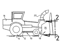
An endless spiralling screw for a snowblower comprising
a rotatable elongated shaft, to be power driven; a first,
elongated, rigid sheet, integrally mounted to the shaft at a
radially inward edge of the sheet and spiralling lengthwisely of
the shaft, the main portion of the sheet having a substantially
straight section, the external marginal portion of the sheet being
folded relative to the main portion thereof, the plane of the main
portion being located downstream relative to the direction of
rotation of the endless screw; at least a few reinforcing struts
being anchored to the spiral sheet and having a smaller external
diameter than the spiral sheet, and being fixedly connected thereto
short of the radially outward edge of the spiral sheet at its
external marginal portion and fixedly secured to the shaft at its
radially inward edge at an area spaced from the securing area of
the radially inward edge of the spiral sheet to the shaft; and at
least a few counterweights, located inside the hollow of the spiral
and integral to a portion of the reinforcing struts, wherein the
counterweights are positioned at selected locations whereby dynamic
axial balancing of the rotating spiralling screw is achieved.


French Abstract

is sans fin hélicoïdale pour souffleuse. Elle comprend : un arbre tournant de forme allongée, à entraînement mécanique; une première plaque rigide et allongée, intégralement et radialement fixée à l'arbre sur un bord pour former une spirale sur la longueur de l'arbre, la plus grande partie de la plaque étant composée d'une section plutôt droite, alors que la partie du bord externe de cette plaque est repliée par rapport à la partie principale, le plan dans lequel se situe cette partie principale se trouvant en aval par rappport au sens de rotation de la vis sans fin; au moins quelques entretoises de renfort fixées à la plaque hélicoïdale et dont le diamètre externe est inférieur à celui de la plaque hélicoïdale, ces entretoises étant fixées à la plaque hélicoïdale sauf au niveau de son bord radial externe, dans sa partie marginale, et fixées à l'arbre au niveau du bord radial interne de la plaque en dehors de la région où le bord radial interne de la plaque hélicoïdale est fixé à l'arbre; et au moins quelques contrepoids, situés à l'intérieur de la partie creuse de l'hélice et incorporés à une partie des entretoises de renfort, ces contrepoids étant placés en certains points choisis pour donner de l'efficacité au mouvement de rotation de cette vis hélicoïdale grâce à un bon équilibrage axial.

Claims

Note: Claims are shown in the official language in which they were submitted.


I claim:

1. An endless spiralling screw for a snowblower collector,
comprising:
(a) a rotatable elongated shaft, to be power driven;
(b) an elongated, rigid sheet member, integrally mounted to said
shaft at a radially inward edge thereof and spiralling along the
lengthwise axis of said shaft, the main portion of said sheet
member having a substantially straight section, the radially
outward marginal portion of said sheet member being folded relative
to said main portion thereof;
(c) rigid, reinforcing, strut members, extending transversely of
said shaft and of said sheet member, said strut members being
provided for preventing deformation of said sheet member under high
load strains; each said strut member having a radial length smaller
than that of said spiral sheet member, and being fixedly connected
to the latter short of but proximate to the radially outward edge
of said sheet member and being fixedly secured to said shaft at its
radially inward edge at an area spaced from the securing area of
the radially inward edge of said sheet member to said shaft; and
(d) counterweight means, located inside and completely concealed
within at least some of said rigid strut members, whereby dynamic
axial balancing of the spiralling screw is achieved once the screw
is submitted to a rotating bias.


2. An endless spiralling screw as defined in claim 1,
wherein each said strut member is anchored to the leading face of
the spiral sheet, i.e. on the leading side of the spiral hollow
defined relative to the spiralling direction defined by said spiral
sheet member.

3. An endless spiralling screw as defined in claim 1,
wherein each said reinforcing member defines a flat, helical
surface.
4. An endless spiralling screw as defined in claim 1,
wherein each said reinforcing strut member defines a generally
triangular shape in plan view.


Description

Note: Descriptions are shown in the official language in which they were submitted.


2~6~
FIELD OF ~HE ~Nv~ ION
This invention relates to the snow removal equipment used
by municipalities, and particularly to the auger screws o~
snowblowers.
CRO~8-REFERENCE DATA
The subject matter of Canadian patent No 704,837 issued
March 2, 1965 in the name of the present assignee, is hereby
incorporated by way of reference to the present patent application.
BACKGROUND OF ~HE l~v~ ON
Canadian patent No 704,837 issued in 19~5 to the present
assignee, discloses an automotive snow blower truck, provided with
a front collector frame unit, 1, defining a front mouth. When the
truck moves forward, incoming ground-standing snow enters into the
collector unit through the front mouth thereof. Two horizontal
endless screws, 6 and 7, superimposed over one another, are carried
inside the collector unit for capturing and crushing incoming snow
and ice, and for conveying the crushed snow and ice toward a snow-
ejecting fan outlet 9 made intermediately of the back wall of the
collector unit 1. Each endless screw includes a power-driven shaft
12 and two elongated sheet members, 18 and 19, integrally mounted
to the shaft 12 and spiralling therealong. ~dditional spiralling
sheet members 25 and 26 are provided to reinforce the first sheet
members 18 and 19. The claimed purpose of the reinforcing sheet
members 25 and 26 is to positively prevent structural deformation
o~ the spiralling sheet members 18 and 19, when the rotating sheet
members 18 and 19 are operatively crushing the incoming snow and

20~62~9
ice .
It is natural for (unloaded) one-entry endless spiralling
screws of snow blower trucks not to be balanced, which means that
these screws will vibrate and jump upon rotation thereof. To
alleviate this problem, weight members are conventionally added to
the exterior face of the spiralling screw, at selected locations,
in order to compensate for the imbalance. However, such weight
members, because they project exteriorly of the outer surface of
the spiralling screw, do form physical obstructions to the free
movement of the ice and snow conveyed by the spiralling screw.
Such obstructions decrease the efficiency and durability of the
spiralling screw.
OBJECTB OF THE lNv~..ION
The gist of the inventior. is therefore to provide axial
15balancing means for the spiralling auger screws of snow blower
trucks, of a type which will not decrease the efficiency and
durability of the spiralling screw.
A corollary object of the invention is to improve upon
the spiral screw disclosed in Canadian patent No 704,837.
20BUMNARY OF TNE Ihv~h~lON
Accordingly with the objects of the invention, there is
disclosed an endless spiral screw for a snowblower collector,
comprising: a rotatable elongated shaft, to be power driven; an
elongated, rigid sheet member, integrally mounted to said shaft at
25a radlally inward edge thereof and spiralling lengthwisely of said
shaft, the main portion of said sheet member having a substantially


209~2~9
straight section, the radially outward marginal portion of said
sheet member being folded relative to said main portion thereof; at
least a few rigid, reinforcing, strut members, extending
transversely of corresponding sections of said shaft and of said
sheet member, said strut members being provided for preventing
deformation of said sheet member under high load strains; each said
strut member having a radial length smaller than that of said
spiral sheet member, and being fixedly connected to the latter
short of the radially outward edge of said sheet member at its
radially outward marginal portion and being fixedly secured to said
shaft at its radially inward edge at an area spaced from the
securing area of the radially inward edge of said sheet member to
said shaft; and counterweight means, located inside and completely
concealed within at least selected ones of said at least a few
rigid strut members, whereby dynamic axial balancing of the
spiralling screw is achieved once the screw is submitted to a
rotating bias.
Preferably, each said strut member radially inward edge
is spaced upstream from the corresponding shaft securing area of
said strut member radially inward edge, relative to the spiralling
direction defined by said spiral sheet - her.
Profitably, each said reinforcing member defines a flat,
spiralwisely~ tilted surface.
Advantageously, each said reinforcing strut member
defines a generally triangular shape in plan view.

~- 2~2~9
BRIEF DESCRIPTION OF THE DRAWINGS
Figure 1 is a side elevation of a snow blower truck according to
the invention;
Figure 2 is an enlarged front elevation of the snow blower truck,
taken from perspective 2-2 of figure 1;
Figure 3 is an enlarged sectional view of the collector screw of
the snow blower of fig 1, taken along line 3-3 of fig 2;
Figure 4 is an enlarged cross-section of the spiral screw, taken
about line 4-4 of fiy 3;
Figure 5 is a perspective view of the collector screw, clearly
showing the integral weight loading mass forming the balancing
means according to the teachings of the invention; and
figure 6 is a cut-away cross-sectional view of the portion of
collector screw bearing the balancing means collector screw.
DE~TT.~n DE8CRIPTION OF TNE l~v~ ION
The snow blower truck 10, illustrated in figures 1-2, is
of generally conventional construction. Truck 10 includes a
chassis 12, carried over ground by wheels 14, a power train 16, a
front loaded snow collector 18, and a snow chute 20 for ejecting
the snow having engaged the snow collector 18. The snow collector
18 defines a back wall 22, a leading edge bottom wall 24, two
opposite lateral (vertical) side walls 26, 28, and an (inclined)
top wall 30. A snow outlet 32 is defined at an intermediate
section of the back wall 22. Two horizontally-extending,
superimposed, endless screw members 34, 36, are rotatably mounted
to the collector unit side walls 26, 28, by known mounting means,


2~2~9
38. Each screw member 34, 36, defines a power driven shaft, 40,
and an elongated, spiralling sheet member 42 of constant pitch
throughout the length of the spiral screw 34 or 36.
According to the invention, each sheet member 42 includes
an intermediate discontinuity, or gap, 44, in facing register with
the snow-ejecting fan outlet 32 of the back wall 22, whereby each
spiral 42 is divided in two laterally spaced half-sections. The
two spiral screw half-sections are not of equal lengths. To each
half section of spiral 42 is fixedly anchored at least a few
transversely extending, lengthwisely spaced, reinforcing strut
members 46. Each transverse strut member 46 is anchored to the
leading face of the spiral sheet 42, i.e. on the leading side of
the spiral hollow relative to the spiralling direction of the
spiral screw. Moreover, each strut member 46 is radially shorter
in length than the spiral sheet 42, so that the radially outward
edge 46a of the strut member 46 is anchored to a (leading face)
section of the spiral sheet 42 which is short of the radially
outward edge 42a of the spiral sheet 42.
As illustrated in figure 5, each strut member 46 may
consist of a number of generally triangular plates 46', 46'',
46''', ..., spacedly interconnected to one another and to tthe
shaft 40 and spiral sheet 42 e.g. by welding W.
According to the heart of the invention, each core body
of the interconnected strut plates 46', 46'', ... of selected ones
of said strut members 46, is integrally ~ormed with a weight
loading mass, 48. The loading mass is concealed within the body of


20~2~9

the strut member 46, and does not project outwardly therefrom in
any way, e.g. the loading mass 48 does not project radially
outwardly of the radially outward edge 42a of the spiral 42, nor
axially of the reinforcing strut members 46. Therefore, the
loading mass 48 does not hamper nor obstruct in any way the free
circulation of snow or ice packs conveyed by the rotating screw 42
toward the snow-ejection fan outlet 32.
The loading mass 48, e.g. a high-density material
embedded into the core of the strut plates, may be for example
lead, or the like, material, provided they are rustproof-treated.
Loading masses 48 are therefore integrally made part of at least
some selected strut members 46. The strut members 46 so selected
are chosen as a matter of balancing the rotating screw, i.e. to
prevent the single-entry screw from vibrating or worse jumping as
the one-entry screw builds up rotating speed. As already explained
hereinabove, ssuch vibrations are the normal outcome of an unloaded
(unbalanced) one-entry rotating spiral screw, which is why weight
loading masses anchored at selected portions of the spiral screw is
essential in view of providing a high performance, substantially
vibration-free spiral screw. It is not required that each and
every strut member 46 include an embedded weight loading mass, but
at least some of the strut members 46 should be loaded in this way,
so as to achieve the axial balancing of the spiral screw. ~low are
the strut members to be loaded selected ? Any acceptable way is
envisioned, for example empirically, i.e. manually, via the trial
and error technique.


Representative Drawing
A single figure which represents the drawing illustrating the invention.
Administrative Status

For a clearer understanding of the status of the application/patent presented on this page, the site Disclaimer , as well as the definitions for Patent , Administrative Status , Maintenance Fee  and Payment History  should be consulted.

Administrative Status

Title Date
Forecasted Issue Date 1997-08-12
(22) Filed 1993-05-14
(41) Open to Public Inspection 1994-11-15
Examination Requested 1995-06-13
(45) Issued 1997-08-12
Expired 2013-05-14

Abandonment History

There is no abandonment history.

Payment History

Fee Type Anniversary Year Due Date Amount Paid Paid Date
Application Fee $0.00 1993-05-14
Registration of a document - section 124 $0.00 1993-10-26
Maintenance Fee - Application - New Act 2 1995-05-15 $50.00 1994-12-15
Maintenance Fee - Application - New Act 3 1996-05-14 $50.00 1996-03-28
Final Fee $300.00 1997-04-11
Maintenance Fee - Application - New Act 4 1997-05-14 $50.00 1997-04-11
Maintenance Fee - Patent - New Act 5 1998-05-14 $150.00 1998-04-09
Maintenance Fee - Patent - New Act 6 1999-05-14 $150.00 1999-04-12
Maintenance Fee - Patent - New Act 7 2000-05-15 $150.00 2000-03-30
Maintenance Fee - Patent - New Act 8 2001-05-14 $150.00 2001-03-16
Maintenance Fee - Patent - New Act 9 2002-05-14 $150.00 2002-04-15
Maintenance Fee - Patent - New Act 10 2003-05-14 $200.00 2003-04-03
Registration of a document - section 124 $50.00 2003-05-08
Registration of a document - section 124 $50.00 2003-08-18
Maintenance Fee - Patent - New Act 11 2004-05-14 $250.00 2004-04-14
Registration of a document - section 124 $100.00 2004-04-20
Maintenance Fee - Patent - New Act 12 2005-05-16 $250.00 2005-04-14
Maintenance Fee - Patent - New Act 13 2006-05-15 $250.00 2006-04-20
Maintenance Fee - Patent - New Act 14 2007-05-14 $250.00 2007-04-12
Registration of a document - section 124 $100.00 2007-06-18
Maintenance Fee - Patent - New Act 15 2008-05-14 $450.00 2008-04-10
Maintenance Fee - Patent - New Act 16 2009-05-14 $450.00 2009-04-30
Maintenance Fee - Patent - New Act 17 2010-05-14 $450.00 2010-04-15
Maintenance Fee - Patent - New Act 18 2011-05-16 $450.00 2011-05-09
Registration of a document - section 124 $100.00 2011-10-25
Maintenance Fee - Patent - New Act 19 2012-05-14 $450.00 2011-12-08
Owners on Record

Note: Records showing the ownership history in alphabetical order.

Current Owners on Record
TENCO INC.
Past Owners on Record
177197 CANADA LTEE
LES MACHINERIES TENCO (CDN) LTEE.
VOHL (1992) INC.
VOHL INC.
VOHL, JEAN-RENE
Past Owners that do not appear in the "Owners on Record" listing will appear in other documentation within the application.
Documents

To view selected files, please enter reCAPTCHA code :


To view images, click a link in the Document Description column. To download the documents, select one or more checkboxes in the first column and then click the "Download Selected in PDF format (Zip Archive)" or the "Download Selected as Single PDF" button.

List of published and non-published patent-specific documents on the CPD .

If you have any difficulty accessing content, you can call the Client Service Centre at 1-866-997-1936 or send them an e-mail at CIPO Client Service Centre.


Document
Description 
Date
(yyyy-mm-dd) 
Number of pages   Size of Image (KB) 
Representative Drawing 1997-08-13 1 5
Cover Page 1995-06-09 1 58
Abstract 1995-06-09 1 43
Claims 1995-06-09 2 65
Drawings 1995-06-09 3 125
Description 1995-06-09 6 270
Abstract 1997-03-04 1 36
Description 1997-03-04 6 239
Claims 1997-03-04 2 53
Cover Page 1997-08-13 1 63
Claims 1998-08-21 2 53
Correspondence 2007-08-21 1 2
Fees 1998-04-09 1 34
Fees 2006-04-20 1 33
Fees 2003-04-03 1 22
Assignment 2003-05-08 17 536
Assignment 2003-08-18 1 43
Fees 2000-03-30 1 30
Fees 2002-04-15 1 29
Fees 2001-03-16 1 28
Fees 1999-04-12 1 29
Fees 2004-04-14 1 26
Prosecution Correspondence 1995-06-13 1 48
PCT Correspondence 1997-04-11 2 92
Examiner Requisition 1996-08-27 2 62
Prosecution Correspondence 1996-12-11 1 45
Prosecution Correspondence 1995-10-20 1 34
Assignment 2004-04-20 19 912
Fees 2005-04-14 1 31
Assignment 2007-04-23 2 66
Fees 2007-04-12 1 32
Assignment 2007-06-18 3 73
Assignment 2007-06-18 3 71
Fees 2008-04-10 1 29
Fees 2009-04-30 1 32
Fees 2010-04-15 1 34
Fees 2011-05-09 1 37
Assignment 2011-10-25 4 147
Fees 2011-12-08 1 32
Fees 1994-12-15 1 38
Fees 1996-03-28 1 42
Fees 1997-04-11 1 40