Note: Descriptions are shown in the official language in which they were submitted.
2~282
A closing system for controlling a flow with precision
This invention relates to a method for closing and opening a
closing system of the gate wall type valve, for controlling with
precision a flow of fluid, either gases and/or li~uids, or of relativ-
ely finely divided loose materials. The invention relates in parti-
cular to gate walls or valves withstanding relatively high pressures,
comprising a closure memher slidable across an opening to control and
regulate the flow of liquid therethrough with precision and without
substantial friction from translational displacement of the closure
member.
A gate wall is usually understood to include a closure member
generally rectangular, a frame surrounding an opening, in which the
closure member is arranged to slide therein and sealing strips bet-
ween the closure member and the frame. Major problems, encountered
with this type of construction, are generally related to the absence
of control regarding the compression of the closure member on its
seat, since only the pressure or mass of the ~luid acts on the clo-
sure member. Also, the friction exerted on the seal, results in seal
wearing, deformation and leakages. Generally, leakage is controllable
on the base portion of the seal: tightness being increased by increa
sing the vertical pressure exerted on the closure member. However, for
the lateral sections, vertical pressure has no influence on the
tightness of the lateral seals. This leakage problem is even more
acute in the upper portion of the seal. Due to the sliding movement,
it is impossible to use sandwich seal strips.
In positive prassure situation, when the pressure is pushing a
losure member against the opening, this type of construction is
acceptable. However, when the pressure is negative, as the closure
member moves away from the opening, serious leakage problems are
- -.
,.:, . : ::,
: . ' . ~: ~ :'
- .: . ,.
: :~
.: : :
.
: .,
2~2g2
encountered with the lateral and upper seals.
Also, in high negative pressure situations, the opening is
difficult, the gate is jammed unless and until pressure egualiæation
is obtained on both sides of the gate, generally by releasing the
pressure in the conduit.
In United States Patent 3,337,178 dated Aug. 22, 1967, Gordon
teaches a valve for finely divided dry particulate matters, positi-
vely closed by a movement toward and away from a valve seat by provi-
ding leaf springs. The valve is operated by changing the convexity of
the springs. Reproducibility is ~unction of the springs, which is
resilient. The stanching could be affected under paxticular circums-
tances such as high pressure or temperature fluctuations. Also, on
increasing o~ convexity of the leaf springs, an oblique displacement
of the closing member is obtained. This non-axial motion produce6
friction of the closing member on the valve sQat and thereby wearing,
deformation and deterioration of the said sealO
In United States Patent 4,524,950 dated June 25, 1985, Vitas et
al., teach improved lateral seals by modifying their position/ propo-
sing oblique fixing with truncated V-shape seals to take advantage of
the vertical pressure on lateral seals.
In United States Patent 4,738,432 dated Apr. 19, 1988, Gardner et
al. tsach two part sealing strips of sandwich type, consisting of a
resilient layer and a superimposed bearing portion arranged to limit
the maximum compression of the resilient portion in closed position.
In United States Patent 4,204,662 dated May 27, 19~0, Reynolds
teaches a valve wherein a negative pressure exerted, on the closure
member, is converted on the peripheral seal in a positive pressure by
using a fulcrum which is located closer to the periphery than to its
center. However, this approach does not solve the sealing problem of
the upper joints or seals when rectangular closure member is used.
.
: ~ ' ...
. :
209~
Also, it is impossible to slide the closure member when a negative
pressure is exerted over it.
In United States Patent 2,999,666 dated Sept. 12, 1961, Sjogren
teaches a valve having a circular closure member pivotally mountad
along its side to an arm fixed to a stem, whereby the stem actuates a
closure member.
In United States Patent 2,767,956 dated Oct. 23, 1956, Rubin
teaches a deformable diaphragm for another type of valves.
In Canadian Patent 1,036,571 dated Aug. 15, 1978, Connor et al.
teach special sealing means for sliding valvesO
In Canadian Patent 803,875 dated Jan. 14, 1969, Combes teaches a
valve with variable gauge portions.
The present invention provides a means to overcome at least some
of the problems enumerated above.
Broadly stated the invention is directed to a closing system of
the gate-wall type valve operating against both positive and negative
pressures, for closing at least one flow opening, comprising-
- a substantially non-deformable closing member for closing at least
one flow opening, said closing member having an axis of symmetry,
- a carriage for translational displacements of said closing member to
and from said at least one flow opening,
~ and mounted on said carriage and operatively connected to said
closing member, non~resilient means for axially displacing said
closing member to and from said at least one flow opening, respec-
tively against said at least one flow opening for closing it, and away
a minimal distance thereof for clearance from said at least one flow
opening,
and cooperating with said carriage and said closing member, a damper
for confining and maintaining said closing member substantially
,: : .. ~
2~9~
perpendicular to axial displacements of said closing member and ensur-
ing said axial displacements, damping and stopping vibrations of said
closing member directed towards said carriagel and transferring or
shunting from said closing member to said carriage via said damper, at
least some of the forcas of said vibrations,
- said carriage being slidably mounted over a pair of sliding guides~
each of said sliding guides being disposed parallel to each other,
adjacent opposite sides of the periphery of said at least one flow
opening, one of the sliding guides being d.isposed on opposite sides o~
said at least one flow openingl said guides acting simultaneously as
supporting means to support said carriage and thereby to counter-
weight a force exerted by a flow against said closing member, ir-
respective of whether said force exerted on said closing member is
subject to positive and negative pressures from said at least one flow
opening,
- non-resilient means for the translational displacement of said car-
riage along said guides and thereby said closing member and operating
independently of said non-resilient means for axially displacing said
closing member,
whereby said damper is damping vibrations of said closing member
toward said carriage and said closing member so damped, is closing
without rotational movements said at least one flow opening by first
axial alignment of said closing member with respect to said flow ope-
ning, by actuation of said non-resilient means for displacing said
carriage and thereby said closing member,
and then said non-resilient means for axially displacing the
closing member is actuated independently of said non-resilient means
for displacing said carriage and free from side displacements of said
carriage to urge said closing member against said flow opening, while
inhibiting translational, side and rotational displacements of said
',
'' ' ~'. ' ~ ' ~
2~628~
closing member on the flow opening,
said flow opening is opened by first actuating said non-resilient
means for axially displacing the closing member away from, but within
a minimal distance of said flow opening, for clearance from said at
least one flow opening, while inhibiting trans].ational, rotational and
side displacements,
and then said non-resilient means for displacing said carriage
and thereby said closing member is actuated to reduce or enlarge said
at least one flow opening, with precision and without substantial
friction from translational displac~ments on the flow opening,
any axial displacement of said closing member being essentially
perpendicular with respect to said flow opening and inhibiting trans-
lational, side and rotational displacements of said closing member.
The vibrations on said closing member due to turbulence are
dampened by said damper always positioned at least within said minimal
distance.
By "non-resilient means'l throughout the disclosure and claims, it
is meant those which are non-elastic, non-springing and are accu-
rately reproducible.
In a preferred embodiment, the system includes a sealing means
cooperating between said closing member and said at least one flow
opening, whereby said means for axially displacing the closing member
is actuated to displace said closing member against and away from said
sealing means, without translational displacement of said closing
member on the sealing means.
Preferably, the closing member is a cupola.
In a preferred embodimPnt the invention is directPd to a closing
system of thP gate-wall type valve operating against both positive and
negative pressures, ~or closing at least one flow opening, compris-
ing:
: :
: . ~ - ..
.~ ~' . . ;~,
:,
:, ~ , ..
~............. .
2~962~2
- a substantially non-deformable cupola for closing at least one flow
opening, said cupola having an axis of symmetry,
- sealing means cooperating between said cupola and said at least one
flow opening,
- a carriage for translat.ional displacements of said cupola to and
from said at least one flow opening,
- and mounted on said carriage and operatively connected to said
cupola, non-resilient means for axially displacing said cupola to and
from said at least one flow opening, respectively against said sealing
means of said at least one flow opening for closing said flow opening,
and away a minimal distance of said sealing means for clearance from
said sealing means of said at least one flow opening,
- and cooperating with said carriage and said cupola, a damper for
confining and maintaining said cupola substantially perpendicular to
axial displacements of said cupola and ensuring said axial displace-
ments, damping and stopping vibrations of said cupola directed towards
said carriage, and transferring from said cupola to said carriage via
said damper, at least some of the forces of said vibrations,
- said carriage being slidably mounted over a pair of sliding guides,
each of said sliding guides being disposed parallel to each other,
adjacent opposite sides of the periphery of said at least one flow
opening, one of the sliding guides being disposed on opposite sides of
said at least one flow opening, said guides acting simultaneously as
supporting means to support said carriage and thereby to counter-
weight a force exerted by a flow against said cupola member, ir-
respective of whether said force exerted on said cupola is subject to
positive and negative pressures from said at least one flow opening,
- non~resilient means for th~ translational displacement of said car-
riage along said guides and thereby said cupola and operating in-
dependently of said non-resilient means for axially di.splacing said
. ................................... .: ~
.. ~........................ .
', ' ` ~ ' ,,
. ~ " '.
' ' . ; ' ~. ,' ,
' ' ' ,~ ' '
'~..'.
cupola, 2 ~9 6 ~ 82
whereby said damper is damping vibrations o said cupola toward
said carriage and said cupola so damped, is closing without rotatio-
nal movements said at least one flow opening by first axial alignment
of said cupola with respect to said flow opening, by actuation of said
non-resilient means for displacing said carriage and thereby said
cupola,
and then said non-resilient means for axially displacing the
cupola is actuated, independently of said non-resilient means f3r
displacing said carriage and free from side displacements of said
carriage, to symmetrically contact and urge the periphery of said
cupola against said sealing means and said flow opening, while provi-
ding a substantially uniform peripheral pressure on the sealing means,
and inhibiting translational, side and rotational displacements of
said cupola on the sealing means and the flow opening,
said flow opening is opened by first actuating said non-resilient
means for axially displacing the cupola away from, but within a
minimal distance of said sealing means for clearance from said sealing
means of said at least one flow openi.ng while i.nhibiting translation-
0 al, rotational and side displacements,and then said non-resilient means for displacing said carriage
and thereby said cupola is actuated to reduce or enlarge said at least
one flow opening, with presision and without substantial friction from
translational displacements on the sealing means of the flow opening,
any axial displacement of said cupola being essentially perpendi-
cular with respect to said flow opening and inhibiting translational,
side and rotational displacements o said cupola.
The invention is also directed to a method to close a closing0 member of the gate wall type valve, comprising:
,.
`:,. ' ' : ` ~ . . ,
,, .
.~. . :
~: :
.. . .~ ' .
2~28~
providing a substantially non-deformable cupola for closing at least
one flow opening, a carriage for translational displacements of said
cupola, means mounted on said carriage to axially displace said cupola
to and from at least one flow opening and a damper mounted on said
carriaga and responsive to said cupola,
actuating said means to axially displace said cupola to and from said
at least one flow opening, respectively against said at least one flow
opening for closing it and away a minimal distance thereof for clear-
ance from said at least one flow opening,
while simultaneously confining said cupola substantially perpen-
dicular to the axial displacements of said cupola, damping vibrations
of said cupola directed towards said carriage, and transferring from
said cupola to said carriage, at least some of the forces of said
vibrations, directly from said cupola to said carriage, via said
damper, thereby said damper reducing vibrations on and extending the
life of said non-resilient means for axially displacing said cupola
and inhibiting translational, side and rotational displacements of
said cupola.
This closing system is able to open with precision the closing
member even when the negative pressure is high. Also, the closing
member can be removed quickly in the front of the flow opening to
permit a quick ~low.
In a particular embodiment, an object of the present invention is
to provide better sealing for a valve of the slide gate type, where
the closing member never acts in friction on sliding on a seal sur-
rounding the flow openingl but only in compression, thereby reducing
wearing, deterioration and deformation of the seal. Also as shown in
all the drawings a damper is provided for damping vibrations of said
closing member toward said carriage. Other objects and advantages of
this invention will be apparent from the accompanying drawings and
; . ., . ;
, : : .
descriptions.
2~6~
In the drawings which illustrate particular embodiments of
the invention,
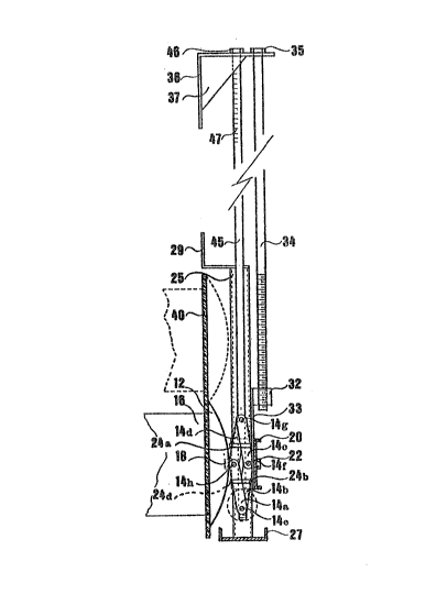
Fig. 1 is an elevational view of a closing system or valve;
Fig. 2 is a detailed sectional view along line 2-2 of FIG. 1
with the closing member in closed position;
Fig. 3 is a cross-section taken a:Long lines 3-3 of Fig. 1
with enlarged portion encircled;
Fig. 4 is an enlarged side view of an other preferred type
of non-resilient means for axially displacing the closing member;
Fig. 5 is a detailed sectional view along line 5-5 of Fig.
4;
Fig. 6 is a view similar to Fig. 5 showing ball bearings
instead of frictionless panels;
Fig. 7 is a top plan view of a closing system using mean for
axially displacing the closing member shown in Fig. 4;
Fig. 8 is a side elevation view where a closing system is
used to close alternatively two flow openings horizontally placed and
using a cable system displacement;
Fig. 9 is a top plan view of a closing system using another
type of sliding guide and means for axially displacing the closure
member;
Fig. 10 is a detailed sectional view along line 10-10 of
Fig. 9;
Fig. 11 is an enlarged perspective view of a portion of the
sliding guide of FigO 9;
Fig. 12 is an enlarged side elevation view of the screw~jack
of Fig. 9;
. .
.
:
.
Fig. 13 is a side fâce view of an other preferred type of a
closing syst~m or valve;
Fig. 14 is a top view of Fig. 130
Figures 1 to 3
Referring to the drawings which i]lustrate some of the
preferred ways of carrying out the invention, and particularly to Fig.
1, a closing system or valve 10 comprises a closing member 12 (prefe-
rably in the form of a cupola as will be discussed herein below),preferably fixedly mounted on a non-resilient means 14 for substan-
tially axially displacing the closing member, for closiny a flow
opening 16, better shown in Fig. 2. The closing member is substantial-
ly non-deformable or rigid.
This non-resilient means, that is one which is non-elastic, non
springing may take numerous forms. In Fig. 1, and better shown in Fig.
3, the closing member 12 is fixedly mounted in its axis of symmetry or
center to a type of jack 14 with a fastening means, for instance a
bolt 18. The jack itself, is fixedly mounted to a carriage 20 with
fastening means, such as bolt 22, between resilient washers sandwich
the cupola. Aside from the stopping means such as 24 which act as a
damper as discussed in the following paragraph, the resilient washers
also damp cupola vibrations and thus act as secondary or auxiliary
dampers thereby protecting by the same way the jack components~
I~ desired as one of the examples only, pins, rods or other
stoppers such as 24a/ 24b, 24c and possibly 24d and more, are sym-
metrically mounted on a carriage 20 with respect to the axis of
symmetry of the closing member, but also other stopping means or dam--
pers may be used as will be discussed herein below, to confine the
axial displacement of the closing member such that any of said axial
.
, .` ` `' ' . ~' '
,
,
:. ,
2~9~2~2
displacements is along an extension o~ said axis of symmetry of said
closing member and to support it: and thereby cooperating between said
carriage and said closing member as a damper or one means to damp
vibrations of said closing member, directed towards said carriage, and
to transfer or shunt from said non-resilient: means for axially dis-
placing said closing member to said damper, at least some of the
forces of said vibrations, directly from said closing member or cupola
to said carriage, via said damper and to confine said cupola substan-
tially perpendicular to said axial displacements of said closing
member, to said carriage, therPby to reduce vibrations on said non-
resilient means for axially displacing said closing member. At least 3
members selected from the group consisting of pins, rods, stoppers and
other dampers similar thereto, are required for a 3-dimension damping
action, said members being mounted on said carriage, in space relation
to the closing member, or cupola as the case may be, and symmetrically
with respect to the axis of symmetry of said cupola or closing member.
The carriage 20 is slidably mounted along a pair of slidiny
guides or columns 25 and 26 defining the carriage track or sliding
guide as well as acting as a supporting means to counterweight the
force exerted against the closing member irrespective of whether said
force on said closing member is subject to positive or negative
pressures, as they themselves are each respectively fixed in a channel
27 at one end and fastening pieces 28, 29 at the other end. In a
particular embodiment, the carriage 20 slides to and from said flow
opening by means of bushings 30, 31 (better shown in fig~ 2) mounted
through said carriage. A positioning nut 32, better shown in Fig. 3,
fixed onto the carriage 20 via bracket 33, receives a threaded stem
3~.
As one of the examples of non-resilient means for the transla-
tional displacement of the carriage along the sliding guides, the
11
:.
.
,
,
: ~ :
2~3~82
other end of th~ stem 34 is provided with a translational displac~-
ment control lever 35 which is seated or mounted on the supporting
bracket 36. The bracket 36 is strengthened with fulcrums 37 which may
be fastened to a wall by using holes 38, 39 or other fastening means.
This translational displacement control lever 35 may be manual or
motor operated.
~ seal 40 cooperates between the periphery of the cupola or of
other closing member for closing at least one flow openin~, and the
periphery of said flow opening. In a preferred embodiment, the seal is
mounted on a wall surrounding the flow opening. As a way of example
only, it may be a medium or high density, high molecular weight poly-
ethylenP sealing panel or a more resilient layer foamed material. Such
panels may be fixed with an adhesive and sealant such as an urethane
adhesive and sealant and the like. Sealing strips and other sealing
means may be used instead of panels, if desired. In some cases, the ~``
sealing means are not necessary, for instance with relatively finely
divided loose materials one can do away with it.
The jack may take various forms, in one of the ways shown in fig.
1 to 3, U-shaped arms 14a, 14b, 14c and 14d are pivotally mounted
ahout shafts, pivots, stub axles, bolts and the like 14e, 14e1, 14f,
14fl, 14g, 14g1 and 14h, 14h1, to define a parallelogram whose arms
are axially displaceable without translational dlsplacement by means
of threaded female members 41 and 42 (better shown in Fig.1) pivotal-
ly mounted about pivots, shafts, stub axles or bolts 14e, 14el, 14g,
14gl: such as, a lozenge, a diamond or a square. The threaded female
members 41 and 42 have respectively holes 41a and 41b, and 42a, 42b to
receive the pivots, shaft, stub axles, bolts and the like 14e, 14el
and 14g, 14gl and threaded holes 41c, 42c to receive a threaded stem
45. The portion of the stem 45 in the region near the threaded female
member 41 and the portion of the stem near the threaded female member
12
~' ~
~ . .
'
:
~6~82
42 are, one clocXwise and the other, counterclockwise in order to
obtain axial displarement without translational displacement. Axial
displacement is ensured by rotation of the adjusting element 46. At
the free end of the stem 45, measuring marks 47 may be provided for
fine tunin~ of the flow control in the conduit. The holes 4la, 4lb,
42a, 42b are shaped as desired, for instance to receive stub axles or
threaded to receive screws or bolts.
The U-shaped arm 14a may be pivotally mounted to the U-shaped arm
14b and to threaded female member 41 in numerous ways: for instance,
as shown in circle of Fig. 3, one side of the U-shaped arm 14a may be
placed against one side of the U-shaped arm 14b, the pivot, shaft,
stub axle or bolt 14e, pivotally mounted to said two sides, is fixed
into hole 41a of said threaded female member 41. The other side of the
U-shaped arm 14b joining the other side of the U-shaped arm 14a are
pivotally mounted about pivot, shaft, stub axle or bolt 14el, said
pivot, shaft, stub axle or bolt being fixed into hole 41b of the
threaded female member 41. Similar arrangements may be provided for
the other pivots, shaft, stub axles or bolts 14g, 14g1 receiving the
threaded female member 42. An other method is to have one end of the
arm 14a larger then one end of the U-shaped arm 14b whereby the side
of the U-shaped arm 14b are positioned within the U-shaped arm 14a and
the threaded female member 41 is positioned within the U-shaped arm
14b. Junction of U-shaped arms 14a, 14d is provided with pivots,
shaft, stub axles or bolts 14h, 14hl and junction 14b, 14c with 14f,
l and are joined together as seen above. The jack 14 is an articu-
lated parallelogram, articulated about pivots. A pair of opposite
articulations has threaded female members mounted about pivots and
fixed into this pair of opposite articulations. Threaded female
members have respectively clockwise and counterclockwise threads and
receive threaded stem 45 in order to produce symmetrical displacement
13
.: , :
:,: - ;: :: . ;. :
' ~ ',
. . ..
: :
' .'
.:
a9~,2
and thereby, substantial axial displacement of the cupola 12. The term
pivot is intended to mean axle joining the opposite sides of the U
shaped arms as well as, stub axles.
OPERATION
As shown in Fiy. 3, the closing member which is in a closed
position, is in open position upon rotation of the adjusting element
46 to increase the distanc~ in size between the stub axles cr bolts
14e, 14el and 14g, 14g1 and thereby decreasing the distance between
the stub axles or bolts 14f, 14fl and 14h, 14hl and producing a reduc-
tion of the compression generated axially against the sealing means
and the closing member. Upon counter rotation of the adjusting ele-
ment 46, the closing member is compressed and urged against the
sealing means 40. In order to completely clear the flow opening, but
with a minimal distance thereof, the adjusting element 46 is rotated
to increase ~the distance in size between the stub axles or bolts 14e,
14el and 14g, 14gl until the ~losing member reaches, as shown in Fig.
2, the pins 24, ensuring this minimal distance from the seal o~ the
~low opening or in its absence, the flow opening. The closing member
becomes fixed to a given position substantially perpendicular to the
axial displacement of the closing member. The translational displa-
cement control lever 35 is then rotated for sliding or displacing the
closing member. This axial displacement is solely to close the flow
opening or to clear the seal or in its absence, the flow opening
away a minimal distance thereo~. When the closing member is displaced
with the carriage, the closing member should be as close as possible
to the sealing means without however exerting friction which might
cause deterioration of the sealing means. For closing systems operat-
ing sewers or water treatments containing pebbles or stones, in order
to let these fall and avoid their pinching between the closing member
14
,
,
..
''' ' ~. ,.
2~6~8~
and the sealing means, a spacing for clearance is used, as an example
only let us say about 1-3 millimeters. As is clearly seen from this
operation, the closing member is closing without rotational movements
flow openings, whila inhibiting translational, side and rotational
displacements on the flow openings. As is clearly seen from Figure 2,
the vibrations on said closing member due to turbulence are dampened
by said damper which is always within said minimal distance for
damping vibrations of said closing member 12. This damper, embodied
for instance in pins, rods or other stoppers such as 24a, 24b, 24c,
protects the non-resilient means for axially displacing the closing
member and particularly the bolt 18, from the stress or pressure
exerted against the cupola, and thus at any time the cupola is damped
from pressures or vibrations exerted on it, because of the damper or
pins, rods stoppers and other dampers, such as 24. The damper may be
embodied in numerous ways, some of which will be discussed herein
below~
This closing system or valve may be used as a flow regulator,
since the closing member may be partially closed. In such a case, the
stem measuring marks 47 of the Fig. 3 may be calibrated with preci-
sion with respect to the size opening. Moreover, this closing system
or valve may be used to control alternatively two flow openings placed
one nsxt to the other. When the flow openings are placed one over the
other, (shown in Fig. 3 by the ~ull line and the doted line) the stem
measuring marks 47 may be used to define the exact position of the two
openings.
Figures 4 to 7
In another preferred embodiment shown in Fig. 4 and 5, the jack
50 comprises slanted nuts 51, 52 axially displaceable and mounted res-
pectively clockwise and counterclockwise about a threaded stem 53. The
stem-extension 54 is secured to the stem 53 with coupling 55. The stem
, ~ , : .
.
; ' 1 .
.. ..
. . ..
: :. ' - '
2096282
53 is mounted onto a U-shaped carriage 56 through carriage wings 56a
and 56b respectively. The stem is rotatively mounted on the carriage
56 with retaining disks 57 and 58, provided with friction- less
washers 59, 60 or ball bearings in order to ease rotation of the stem.
The cupola 67 is secured to the rider 63 with bolt 68. The rider has,
in his center, a threaded hole for receiving bolt 68. Bolt 68 is leak-
proo* with resilient washers 69 and 70 sandwich in between the cupola.
These washers 69, 70 have also a minor contribution to damp cupola
vibrations and to that extent protecting the jack components. The .
rider is secured into slanted nuts 51 and 52 with rails or track 64,
better shown in Fig. 5O In between the rider and the slanted nuts,
frictionless panel 65 or ball bearings 651 (better shown in Fig. 6) or
other compatible means to overcome friction is provided. An other
frictionless panel 66 or ball bearings 661 (better shown in Fig. 6) or
other means to overcome friction positioned between slanted nuts and
carriage 56 ease the sliding movement of nuts on the carriage.
Instead of the pins 24 shown in Figures 2 and 3, if desired, the
damper also acting as stopping means, is at least and preferably, 2
sets of male-~emale devices, devices including arrangements, teles-
copically or slidably, and symmetrically mounted on, and with respect
of the axis of s~mmetry of the cupola, to bridge the cupola or other
closing member to the carriage: 72a, 72b is an example illustrating
such a set.
For each of the male-female arrangements or devices, one of the
elements male or female, is operatively connected to the carriage and
the other to the closing member~ For example in each pin-tube or rod-
tube arrangements, one of these elements is connecting the periphery
of the cupola (the pin such as 72 in the Figure 4) slidable in or over
the other element secured to the U-shaped carriage 56 (slidable in the
tubes such as 72a and 72b in the Figure 7).
lÇ
: '
: , :
2Q9~2
These dampers are used to confine and maintain the axial dis-
placements o~ the cupola, to ensure said axial displacements and to
add further peripheral support of the cupola when the cupola is
resting against it, to cooperate between said carriage and said
closing member to damp at least some of the vibrations of said closing
member, directed towards said carriage, and to transfer or shunt said
vibrations from said closing member or cupola to said carriage, via
said means to damp, thereby by-passing and extending the life of said
non-resilient means to axially displace the cupola or the closing
member.
It should be noted that the minimal distance for clearance of the
closing member is given by the female elements, for instance the tubes
such as 72a, 72b, which stop short of the cupola, as seen in Figures 7
and 4.
Rotation of the stem 53 generates the axial displacement of the
rider 63. The rider has, opposite to the cupola 67, a V-shaped sur-
~ace. The apex of the V-shaped surface and the cupola center are in
the same axis of symmetry. The rider slides into slantsd nuts rails 64
and is confined thereto. The slanted nuts, tapering toward the same
axis of symmetry, upon a clockwise or counterclockwise rotation of the
stem 53 are displaced symmetrically away from each other or toward
each other, with respect to the same axis of symmetry, producing the
axial displacement of the cupola 67. As shown in Fig. 7, the carriaga
56 is slidably mounted on the sliding guides 74 and 75, acting simul-
taneously as a supporting means to counterweight the force exerted
against the cupola 67, irrespective of whether said force exerted on
said closing member is subject to positive or negative pressures and
to cooperate with a mechanism producing the translational displacement
of the cupola. In order to avoid undue repetition, detailed descrip-
tion of the sliding guides 74 and 75, which correspond to the descrip-
17
, ', '' " '~ :
tion here and below in figures 9 and 11 of sliding guides 123 and 124is not given~
Figure 8
As shown in Fig. 8, the flow opening 97 and a similar one 98,
covexed by the closing member 90, may be vertically or horizontally .-
positioned. The closing member 90, is mounted on the carriage 89
having sliding guides 91, 92 themselves horizontally mounted on a
surrounding wall. The translational displacement may be obtained with
a mechanism comprising a pair of member selected from the group con-
sisting of drivenly mounted continuous belts, endless chains or cables
93 and 193 mounted on idle, pulleys, toothed wheels or guiding drums
94 and 194 and driving pulleys, toothed wheels or guiding drums 95 and
195. The carriage 89 mounted on said mechanism travels between, pul-
leys, toothed wheels or guiding drums 94, 95 and 194, 195. The pair of
pulleys, toothed wheels or guiding drums are synchronized by the
rotation of the stem 96 mounted onto holder 197. Stem 96 may be
operated with a hand handle or a motor dri~e 99.
Figures 9 to 12
The non-resilient means for axially displacing the closing member
need not to be a jack of the type shown above, though preferred, but
could be mechanic, including cam, or fluid operated including hydrau-
lics and pneumatics systems: as a way of example only, in Fig. 10-12,
a screw-jack type is used as an alternative mechanic system in as-
sociation with a diffusing ring, a cupola 102 is Eixedly and axially
mounted onto a diffusing ring 103 at one of its open end ~better shown
in the circle of Fig. 10).
The diffusing ring 103 is provided at its opposite open end with
radial elements such as 103a, 103b, 103c, 103d equally disposed such
18
'
2~2~
that a uniform pressure about the central portion of the ring is
equally distributed along the periphery of the ring and thereby
e~ually distributed on the cupola and on which radial elements said
means for axially displacing said cupola is acting to push said
cupola.
This diffusing ring 103 is slidably or telescopically mounted
onto a carriage 104 with fastening means such as pins or rods 105, 106
s~mmetrically disposed and receiving female elements such as slots or
tubes 107, 108 provided on the carriage. In between the diffusing ring
and the carriage a jack 109 is axially mounted and fixed on the
carriage only, for reducing over loading on jack with closing member
as well as the vibrations caused on the closing member in hiyh pres-
sure situation, thereby extending the life of the jackO
This arrangement is another example of damper to confine and
maintain said cupola substantially perpendicular to said axial dis-
placements of said closing member and ensure said axial displacements,
cooperating between said carriage and said closing member as one means
to damp vibrations of said closing member, to transfer and stop at
least some of the forces of said vibrations, from said closing member
or cupola to said carriage, via said damper, by-passing and extending
the life of said non-resilient means for axially displacing said
closing member.
It should also be borne in mind that inversely the pins or rods
might be secured to the carriage and the receiviny element defined in
the diffusing ring.
If the pressure exerted against the cupola 102 is high, the
cupola will automatically be pushed away by said pressure. If the
pressure is low, biassing means such as spring 110 tenlarged in the
circle of Fig. 9~ may be used to move away the closing member.
As can be easily seen, in summary in a particular embodiment, the
19
.. : ,.. . ..
, ;.
. '. ': :.':
. .. ,, -
': ' ~
2 8 2
cupola is mounted on a diffusing ring, said ring having opposite open
sides, one of said opposite open sides being coaxial with said axis of
symmetry of said cupola, and said ring on the other of said opposite
open sides being slidably mounted on said carriage,
the non-resilient means for axially displacing said cupola being
disposed along the axis of symmetry of said cupola and thereby said
ring slidably mounted on said carriage acting as said damper.
As shown in Fig. 10 and 12, the screw-jack 109 is fixedly mounted
onto the U-shaped frame of the carriage 104. It is actuated via one
wheel of gearing system or bevel gear 110 by actuating a connecting
rod 111 generally terminating into a manually operated handle or a
motor operated system. The threaded stem 112 is fixed to the other
wheel of the gearing system causing axial displacement of the threaded
piston 113. The piston 113 pushes on the diffusing ring at its center,
axially displacing the closing member 102 with respect to the flow
opening 114, without translational displacement.
Instead of screw-jack, a fluid operated jack, having a positive
driving action to axially displace the closing member to and fro the
flow opening, could be used.
A sealing means 115 cooperates between the closing member and the
flow opening.
The closing system may also comprise other types of non-resi-
lient means for the translational displacement of the means for
axially displacing the closing member. As shown in Fig. 9 and 11, the
carriage 104 is provided with reinforcing beams such as shown at 11
which may join the opposite inner sides of the U-shaped frame. Two
parallel brackets 117 and 118 are fixedly mounted along one of their
respective longitudinal ends, onto the opposite outer sides of the
U-shaped frame of the carriage 104, and a band 119 and 120 of their
;: ' ` ' ' :
.....
2V9~3'~
respective outer~ost free ends is bent outwardly at an obtuse angle,
as to define a V-shaped cro~s-section at said free ends. Reinforcing
brackets 121 and 122 respectively cooperate to strengthen said V-sh-
aped cross-sections at the free ends.
The two parallels rails or sliding guides 123 and 124 are fixedly
mounted onto a wall surrounding the flow opening~ Each of the rails or
guides has a band 125 and 126 along one of it longitudinal end bent
oukwardly at an obtuse angle corresponding to the obtuse angle of the
bands llg and 120, as to define a V-shaped cross-section for confining
bands 119 and 120 within the bands 125 and 126 as well as enabling
sliding thereon and as counterweight of force against said cupola.
Fulcrums 127 and 128 strengthen the "V" parts of those rails. Although
reference is made to a V-shaped, it should be understood that U-
shaped and other tongues and slits may be used if desired. Also other
sliding guides or railing systems may be used for confining the car~-
riage, enabling sliding thereof and acting as supporting means to
support said carriage and thereby to counterweight a force whether
positive or negative exerted by a flow against said closing member.
Figures 13 and 14
In Figures 13 and 14, for closing the flow opening 151, a cupola
152 is axially fixed to a plate 154. A diffusing ring 1~3 which may be
non-resilient or slightly resilient, is positioned between the cupola
152 and the plate 154. The ring 153 has opposite open sides, one of
said opposite open sides being coaxial with said axis of symmetry of
said cupola and fixed thereto by said fastening device 269 which
comprises a nut and bolt with a single resilient washer 268. The ring
on the other of said opposite open sides is slidably mounted on a car~
riage 1580 The plate 154 which is a part of the damper, as will be
21
:: . : !
: ' ' : "' ` :' ,
:, , , ~:.
~: :,, :
2~9~2
explained herein below, comprises opposite parallel walls or exten-
sions 155, 156 away from the cupola. These walls may be integral with
the plate or fastened to the plate. As an example only, the walls may
be ultra~high molecular weight polyethylene and the like.
The non-resilient means to axially displace the cupola has a
threaded rod or stem 157 rotatably mounted through opposite walls of a
U-shaped carriage 158 by means of retaining disks 257 and 258. A pair
of blocks 161 and 162, at least one of the block, e.g. 162 is provi-
ded with inner threads for engaging the threaded rod 157. These
blocks are operatively connected, via their respective links 165a,165b
provided at both ends with a shaft~ to a pushing block 163 slidable
between L-shaped slotted guides 164 secured to the plate 154,for
urging the pushing block against the plate 154 and thereby the cupola.
One shaft of each link extends through the pushing block 163 and the
slot of the guides 164. It should be noted that the other block e.g.
161, may either be eliminated by directly joining the link to the
carriage 158 or secured to the carriage as shown in Figure 13 or
provided with inner threads for engaging the threaded rod 157, in such
a case one of the block has clockwise and the other counterclockwise
threads and is functioning as already discussed with the stem of the
non-resilient means to axially displace the cupola of Figure 3. In
these first and third choice the link is idle, the damper controlling
th~ axial displacement of the cupola. The rod at its end opposite said
carriage, is threaded and slidable through a supporting bracket 168,
the threaded end receiving a double action bolt. This double action
bolt comprises a first bolt element 169 used for displacing the
carriage and a second bolt element 166 preferably in the form of a
truncated cone, for releasably locking or fastening the first bolt
element 169 to the stem or rod 157, upon rotation to axially displace
22
.~. : ,:
:; .,,.: . , ;,
.. ": `
. ': '
2 ~ 2
the cupola, and upon sliding of the stem to displace the carriage, the
same rod operating independently said carriage and said non-resilient
means for axially displacing said closing member.
The carriage 158 is slidably mounted and withheld in rails 223,
224 which are similar to the rails ~23, 12~ of Figure 11 described
herein above, but other rails to withhold and to slide the carriage
may be used.
The damper comprises the free end of the opposite walls of the U-
shaped carriage 158 receiving respectively the opposite walls or
extensions 155 and 156 of the plate 154 to enable sliding of said
opposite walls or extensions over said U-shaped carriage. The gap
between the plate 154 and the free end of the opposite walls of the U-
shaped carriage 158 when the cupola is closed, determining the minimal
distance of clearance of the cupola. This damper is confining and
maintaining said cupola substantially perpendicular to any axial dis-
placement of said cupola and ensuring said axial displacements,
damping and stopping vibrations of said cupola towards said carriage,
and transferring at least some of the forces of said vibrations,
directly from said cupola to said carriage via said damper, by-passing
and thereby extending the life of said non-resilient means for axially
displacing said cupola.
If desired, instead of the diffusing ring 153 rods, pins, tubes
or other discontinuous protruding elements may be used for equally
distributing to said plate 157 some of the forces exerted against the
cupola towards said non-resilient means to axially displace the
cupola.
23
:.. .:: .,;:
2~9~'~8~
With the present closing systems, the counter pressure exerted on
the closing member is more effective to close the flow opening com-
pared to the conventional one. The force or pressure exerted is more
equally distributed, even more so when a cupola is used instead of the
reckangular gate. Also, the axial displacement of the closing member
coupled with the rails or sliding guides ease closing member transl-
ational displacement irrespective of the flow pressure exerted. Also
it should be appreciated that. without the damper the non-resilient
means to axially displace the cupola would have a r~latively short
life expectancy as the cupola would tend to move in all directions. If
present, seal means would also deteriorate.
In accordance with this invention a new method to close a closing
member of the gate wall type valve is obtained by:
providing a substantially non-deformable cupola for closing at least
one flow opening, a carriage for translational displacements of said
cupola, means mounted on said carriage to axially displace said cupola
to and from at least one flow opening and a damper mounted on said
carriaga and responsive to said cupola,
actuating said means to axially displace said cupola to and from said
at least one flow opening, respectively against said at least one flow
opening for closing it and away a minimal distance thereof for clear-
ance from said at least one flow opening,
while simultan~ously confining said cupola substantially perpen-
dicular to the axial displacements of said cupola, damping vibrations
of said cupola directed towards said carriage, and transferring from
said cupola to said carriage, at least some of the forces of said
vibrations, directly from said cupola to said carriage, via said
damper.
24
' :,:...
'` ~
:: :
2~6~2
Without elaborating further in explanations inherent to the
parent application but given to ease understanding, and while some of
the preferred embodiments have been described herein above, it is to
be understood that the invention is not to be construed as limited to
these preferred embodiments, as many modifications are possible within
the spirit and scope o the appended claims.
,: ~ : ' i: . , : ~