Language selection

Search

Patent 2096290 Summary

Third-party information liability

Some of the information on this Web page has been provided by external sources. The Government of Canada is not responsible for the accuracy, reliability or currency of the information supplied by external sources. Users wishing to rely upon this information should consult directly with the source of the information. Content provided by external sources is not subject to official languages, privacy and accessibility requirements.

Claims and Abstract availability

Any discrepancies in the text and image of the Claims and Abstract are due to differing posting times. Text of the Claims and Abstract are posted:

  • At the time the application is open to public inspection;
  • At the time of issue of the patent (grant).
(12) Patent Application: (11) CA 2096290
(54) English Title: PIPETTING DEVICE
(54) French Title: DISPOSITIF DE PRELEVEMENT PAR PIPETTE
Status: Dead
Bibliographic Data
(51) International Patent Classification (IPC):
  • B01L 3/02 (2006.01)
  • B01F 11/00 (2006.01)
  • G01N 35/10 (2006.01)
  • G01N 35/00 (2006.01)
(72) Inventors :
  • KRESSIRER, RUDOLF (Germany)
(73) Owners :
  • DADE BEHRING MARBURG GMBH (Germany)
(71) Applicants :
(74) Agent: BERESKIN & PARR LLP/S.E.N.C.R.L.,S.R.L.
(74) Associate agent:
(45) Issued:
(22) Filed Date: 1993-05-14
(41) Open to Public Inspection: 1993-11-16
Examination requested: 2000-05-01
Availability of licence: N/A
(25) Language of filing: English

Patent Cooperation Treaty (PCT): No

(30) Application Priority Data:
Application No. Country/Territory Date
P 42 16 128.2 Germany 1992-05-15

Abstracts

English Abstract


Abstract of the disclosure

Pipetting device

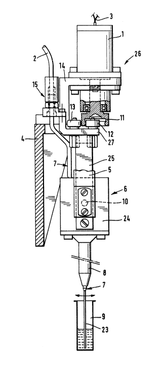
In the pipetting device for mixing liquids, a pipetting
tube (7) is located in a receiving arrangement (6), and
the receiving arrangement (6) is rotatably (10) mounted
in a mounting device (5) and connected via a coupling
(12, 13) to an eccentric drive (26).


Claims

Note: Claims are shown in the official language in which they were submitted.


- 4 -
THE EMBODIMENTS OF THE INVENTION IN WHICH AN EXCLUSIVE
PROPERTY OR PRIVILEGE IS CLAIMED ARE DEFINED AS FOLLOWS:
1. A pipetting device for mixing liquids, wherein a
pipetting tube (7) is located in a receiving
arrangement (6), and the receiving arrangement (6)
is rotatably (10) mounted in a mounting device (5)
and is connected via a coupling (12, 13) to an
eccentric drive (26).

2. A device as claimed in claim 1, wherein the coupling
comprises two pressure rollers (12, 13) and the
eccentric drive (26) comprises an eccentric (11)
which is arranged on the shaft of a motor (1).

3. A device as claimed in claim 1, wherein the eccen-
tric drive (26) is arranged on the mounting device
(5) for the receiving arrangement (6).

4. A device as claimed in claim 1, wherein the pipet-
ting tube (7) is provided with a heating device (16,
17) and is divided into two zones (21, 22), where
the first zone (21) contains the pipetting tip (23)
which has a relatively small pipetting volume, and
the second zone (22) connected thereto has a pipet-
ting volume larger than the first zone.

5. A device as claimed in claim 4, wherein the pipet-
ting tube (7) is straight in the first zone (21) and
coiled in the second zone (22).

6. A device as claimed in claim 4, wherein the pipet-
ting tube (7) is in contact with a heat-conducting
heat transfer means (16) in the region of the second
zone (22).

7. A device as claimed in claim 1, wherein the pipet-
ting tube is provided with a coupling (15) for a
feedline (2) which is located on the receiving
arrangement (6).

Description

Note: Descriptions are shown in the official language in which they were submitted.


2~962~
BEHRINGWERKE AG ~OE 92~B 012 DPh. HS/we

Description

Pipetting device

The invention relates to a pipetting device for mixing
liquids.

For quantitative protein determination in body fluids
such as, for example, serum, urine or spinal fluid, the
latter are diluted where appropriate and mixed with
reagent (anti6erum) in a defined ratio by volume, and the
turbidity occurring owing to the reaction is measured.
The liquids are manipulated with pipetting devices and
mixed with a separate stirrer. The disadvantages con-
nected with this are the additional space required for
the stirrer, and the additional cross-contamination with
sample material, which influences the accuracy of the
result3 mea~ured in sensitive assays. A further disadvan-
tage i6 the additional heat introduced by the stirrer,
which interfere~ with keeping the reaction temperature
con~tant and thus likewise influences the accuracy of the
results measured.

The intention of the invention is to remedy this. The
invention achieves the object by a pipetting device in
which a pipetting tube is located in a receiving arrange-
ment, and the receiving arrangement i8 rotatably mounted
in a mounting device and connected via a coupling to an
eccentric drive.

The coupling can comprise two pressure rollers and the
eccentric drive can comprise an eccentric arranged on the
shaft of a motor. The eccentric with motor can be
arranged on the mounting device for the receiving
arrangement. The pipetting tube can be provided with a
heating arrangement and be divided into two zone6, where

- 2 - 2~62~
the first zone contain~ the pipetting tip which has a
relatively small pipetting volume, and the second zone
connected thereto has a larger pipetting volume than the
first zone. The pipetting tube can be straight in the
fir~t zone and be coiled and in contact with a heat
transfer means in the ~econd zone. The pipetting tube can
furthermore be provided with a coupling for a feedline
which is located on the receiving arrangement.

The advantage~ of the invention are essentially to be
regarded as the possibility of achieving metered volumes
for the individual components aR far as 2 ~l with an
accuracy of 1%, and mixing of the components.

The invention is explained in detail hereinafter hy means
of an exemplary embodiment from which other important
features are evident. Figure 1 shows the pipetting device
from the front, partly in section, and Figure 2 show~ the
pipetting device from the side, partly in section.

The pipetting tube (7) is located in a receiving arrange-
ment (6). The receiving arrangement (6) is composed of a
U-shaped ~rame (25) and a casing (24). The ~rame (25) is
rotatably mounted on a mounting device (5) via a link
(10) and connected via a coupling, for example pressure
rollers (12, 13), to an eccentric drive (26). The eccen-
tric drive (26) i8 es~entially compo~ed of the eccentric
(11) and the motor (1) with feedline (3). The eccentric
drive (26) is located on the mounting device (5), and the
mounting device (5) is provided with a support plate (4).
The frame (25) is provided with a cross arm (27) which
supports the pressure rollers (12, 13) and a coupling
(15) which establishes the connection of the pipetting
tube (7) to an elastic feedline (2). The pipetting tube
(7) has a first zone (21) which is designed to be
straight and supports the pipetting tip ~233 with a
relatively small pipetting volume, and has a ~econd zone
~22) which is connected thereto and is designed a~ a


.
.

'. - . . ~................ - .
- . . -- : - .

2~2~
coil. The pipetting tu~e (7) is provided with a heating
device (17) in the first zone (21) and with a heat
transfer means, a heating cartridge (16), in the second
zone. The heating devices (16, 17) can operate separately
from one another. (8) indicates a supporting tube for the
straight part (zone 21) of the pipetting tube (7), (18,
19) indicates the fPedlines for the heating devices (16,
17), (14) indicates the mounting device for the motor
(1), and (20) indicates a temperature sensor. The ec
centric drive (26) causes the pipetting tube (7), as
indicated by the arrow, to execute a backwards and
forwards oscillatinq motion, which agitates, and thus
mixes, the contents of the cuvette (9).


.

' . ' ' .- ' .
- . ........... ' , ' ~ ' ~ , ,
.- . . - . . ~ .
Representative Drawing
A single figure which represents the drawing illustrating the invention.
Administrative Status

For a clearer understanding of the status of the application/patent presented on this page, the site Disclaimer , as well as the definitions for Patent , Administrative Status , Maintenance Fee  and Payment History  should be consulted.

Administrative Status

Title Date
Forecasted Issue Date Unavailable
(22) Filed 1993-05-14
(41) Open to Public Inspection 1993-11-16
Examination Requested 2000-05-01
Dead Application 2002-05-14

Abandonment History

Abandonment Date Reason Reinstatement Date
2001-05-14 FAILURE TO PAY APPLICATION MAINTENANCE FEE

Payment History

Fee Type Anniversary Year Due Date Amount Paid Paid Date
Application Fee $0.00 1993-05-14
Registration of a document - section 124 $0.00 1993-11-30
Maintenance Fee - Application - New Act 2 1995-05-15 $100.00 1995-05-01
Maintenance Fee - Application - New Act 3 1996-05-14 $100.00 1996-05-01
Maintenance Fee - Application - New Act 4 1997-05-14 $100.00 1997-04-25
Registration of a document - section 124 $50.00 1997-10-27
Maintenance Fee - Application - New Act 5 1998-05-14 $150.00 1998-04-24
Registration of a document - section 124 $50.00 1998-12-07
Maintenance Fee - Application - New Act 6 1999-05-14 $150.00 1999-04-29
Maintenance Fee - Application - New Act 7 2000-05-15 $150.00 2000-04-25
Request for Examination $400.00 2000-05-01
Owners on Record

Note: Records showing the ownership history in alphabetical order.

Current Owners on Record
DADE BEHRING MARBURG GMBH
Past Owners on Record
BEHRING DIAGNOSTICS GMBH
BEHRINGWERKE AKTIENGESELLSCHAFT
KRESSIRER, RUDOLF
Past Owners that do not appear in the "Owners on Record" listing will appear in other documentation within the application.
Documents

To view selected files, please enter reCAPTCHA code :


To view images, click a link in the Document Description column. To download the documents, select one or more checkboxes in the first column and then click the "Download Selected in PDF format (Zip Archive)" or the "Download Selected as Single PDF" button.

List of published and non-published patent-specific documents on the CPD .

If you have any difficulty accessing content, you can call the Client Service Centre at 1-866-997-1936 or send them an e-mail at CIPO Client Service Centre.


Document
Description 
Date
(yyyy-mm-dd) 
Number of pages   Size of Image (KB) 
Cover Page 1994-03-12 1 20
Abstract 1994-03-12 1 10
Claims 1994-03-12 1 41
Drawings 1994-03-12 2 61
Description 1994-03-12 3 112
Representative Drawing 1998-08-27 1 17
Assignment 1993-05-14 8 288
Prosecution-Amendment 2000-05-01 1 57
Prosecution-Amendment 2000-07-12 1 31
Fees 1996-05-01 1 45
Fees 1997-04-25 1 81
Fees 1994-05-01 1 89