Note: Descriptions are shown in the official language in which they were submitted.
2Q96557
HOSE CLAMP INCORPORATING TIGHTENING SCREW
The present invention relates to a hose clamp
incorporating tightening screw.
A hose clamp is already known, particularly by
S Patents US 2,522,494 and DE-A-41.08.852 or by published
International Applications W080/01199 and W087/00602,
which is constituted by a band of flexible material,
generally metal, wound on itself. One of the ends of
the band presents, at least on its outer surface, a
regular succession of crests and/or troughs forming a
rack. On the other end of the band is fixed a housing
essentially presenting two lateral sides and
constituting the support of a screw which is mounted to
pivot about its axis. This latter is itself
substantially parallel to the longitudinal direction of
the band, i.e., to a tangent to the clamp when the band
is wound on itself. The longitudinal position of the
screw with respect to the housing is variable and
determined by at least one stop, axially mobile with
respect to the housing, against the action of a spring.
On this stop there abuts an appropriate zone of the
tail of the screw. In certain cases, the screw is held
in the housing thanks to an approximately cylindrical
shape of the latter; in other cases, two bearings may
be provided, receiving the threaded shank of the screw,
respectively near its head and its tail.
Finally, the housing presents a transverse slot
via which penetrates the free end of the band whose
relief elements come into mesh with the threads of the
screw, this allowing the band to be tightened by
rotation of the screw with the aid of an appropriate
tool.
This type of clamp incorporating tightening screw
is much used in industry, particularly if it is desired
- 2 2096557
automatically to compensate a possible reduction in the
diameter of the object tightened, but it generally
presents at least one serious drawback.
In fact, the known clamps do not allow the
clearances to be taken up at the moment of tightening;
in certain cases, it may be observed that the threads
of the screw are disengaged from the rack of the band,
thus preventing continued tightening of the clamp.
The present invention is directed towards the
provision of a hose clamp incorporating tightening
screw of the type which has just been recalled, whose
design avoi3s the drawback which has been set forth
hereinbefore.
According to the invention, there is provided a
hose clamp including a tightening band, one of the ends
of the band forming a rack and the other end of the
band affixe~~ to a tightening means, wherein the
tightening means includes: a housing affixed to the
band; a screw having a longitudinal axis, the screw
having a tail portion at one end and a head portion at
the other e:zd, and mounted in the housing in such a
fashion to ~~ermit pivotal and axial movement of the
screw relative to the housing; and a curved spring
blade havin~~ first and second ends mounted in spaced
apart relation to the housing, the first end provided
with an opening adapted to receive the tail portion of
the screw, i_he second end provided with an opening to
at least partially surround the screw in the vicinity
of the head portion thereof, the second end of the
spring bladE~ being mounted to the housing to permit
relative sliding movement therebetween.
The invention will be more readily understood on
reading the following description with reference to the
accompanying drawings, in which:
2a 2 0 9 6 5 5 7
Figure 1 is a view in elevation from the side of
the hose clamp according to the invention;
Figure 2 is a view similar to Figure 1, a lateral
wall of the housing having been torn away; and
S Figure 3 is a view in the direction of arrow F of
Figure 1.
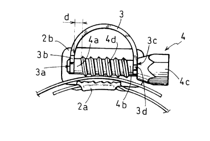
Referring now to the drawings, Figures 1 to 3 show
_.. 2~,,,9,~J~,..'
-3-
a hose clamp incorporating tightening screw, constituted
by a generally metal band 1 wound on itself and presenting,
at least at its outer end la, troughs and crests forming
a rack lb. On the inner end lc is fixed a housing 2 consti-
tuted by a simple U-shaped stirrup of which the web 2a,
located in the central zone of the housing, is assembled
on the band by a.ny appropriate means, such as welding
or riveting, or even by passage of the band in slots
in said web.
Between the lateral sides 2b of the housing is dis-
posed a curved ~~lade 3, generally made of spring steel,
for example of semi-circular profile, whose concavity
faces the inside of the clamp. The ends of the blade
are in contact with the sides of the housing and the
blade is thus captive therebetween.
A first end, designated by 3a and located to the
left in Figures 1 and 2, is fixed to the housing. To
that end, the blade 3 presents two lateral extensions
3b which penetrate in holes 2c made on each of the sides
2b. The projections of the lateral extension 3b are prefe-
rably hammered on the outer face of the walls 2b or present
a hook shape to ensure locking thereof on these sides.
At its opposite end 3c, the blade 3 advantageously
presents two lateral extensions 3d disposed in elongated
slots 2d in the lateral sides 2b of the housing.
In this way, the blade 3 is axially immobilized
with respect to the housing 2 at its end 3a, but is axially
mobile at its end 3b, at least over the axial length
of the slots 2d forming slideway. For reasons which will
appear hereinbelow, the lower edge 2e of the slots 2d
is advantageously inclined in the direction of the central
zone of the housing.
Finally, a screw 4 is disposed between the lateral
sides 2b of the housing and its axis is substantially
parallel to the web 2a of the housing, i.e. to the longitu-
2G9~5~':'
-4-
dinal direction of the band in this region; it is main-
tained in its housing by the judiciously shaped ends
3a and 3c of the blade 3.
In fact, the end 3a presents an at least partially
circular opening 3e, forming bearing, in which is engaged
the cylindrica:_ end of the tail 4a of the screw 4. On
the other hand,. the end 3c is shaped in similar manner
and may likewise receive a cylindrical portion 4b of
the shank of tree screw, located in the vicinity of its
head 4c.
It will be emphasized here that the cylindrical
portion 4a of t:he tail of the screw extends, this side
of the end 3a of the blade 3, over a certain distance
d when the head 4c of the screw is in abutment, before
the clamp is tightened, on the mobile end 3c of the blade.
In practice, it. will be advantageous, for reasons which
will be apparent hereinbelow, if the distance d is close
to the axial length of the slideway 2d.
Between the inner ends of the cylindrical portions
4a and 4b, the threaded zone 4d of the screw is located.
Band 1 being fixed to housing 2 as described, its
outer end la i~; introduced, by the left in Figures 1
and 2, in the =;lot located between web 2a of the housing
and the threaded zone 4d of the screw. By rotating screw
4 in the suitable direction, the end la advances from
left to right a.nd reduces the diameter of the clamp.
then the clamp is mounted on the object to be tigh-
tened, the continuing movement of rotation of the screw
4 provokes tightening, the head 4c of the screw abutting
on the stop constituted by the end 3c of the blade 3.
As tightening ~~ecomes more intense, blade 3 deforms under
the effect of the force exerted by the screw head 4c
on the end 3c, the latter moving somewhat closer to the
end 3a fixed tc the housing 2.
The characteristics of the blade 3, which thus forms
l~r~~~JJ~h
-5-
spring, will be determined as a function of the tightening
effort which must be applied to the object to be tightened;
similarly, the screwing torque exerted on the head of
the screw 4 will take into account the desired tightening
effort, particularly if it is obtained by means of a
motorized screw driver. It is thus possible to limit
the tightening effort to any suitable value.
On the oth?r hand, after appropriate screwing, the
distance d visible in Figure 2 will have notably decreased,
with the result that blade 3 will be compressed.
If, during use, the diameter of the object tightened
were to decrease, blade 3 would tend to resume its initial
shape, thus ensuring maintenance of a sufficient clamping.
As the man skilled in the art will already have
understood, manufacture of the clamps according to the
invention is particularly simple.
The housing essentially presents holes or the like
intended to rec~sive the lateral extensions of the ends
of t?~e blade to ensure immobilization of one of these,
ends and to allow axial displacement of the other. The
web of the housing and the band of the clamp, as well
as the blade and the screw being assembled, these two
sub-assemblies are fastened on each other by a simple
folding of the lateral sides of the housing; this single
operation constitutes the stirrup which imprisons the
blade and the screw, the clamp then being ready for use.
However, this operation which may be effected on
automatic presses by a succession of folding and stamping
operations, nonetheless leaves "clearances", for example
for the ends 3a and 3c of the blade between the lateral
sides 2b of the housing and for the lateral extensions
3b in the holes 2c. During tightening, the inclination
of the threads of the screw with respect to the axis
of the band causes a slight lateral displacement of the
screw, enabling the clearances to be taken up; simultaneous-
2C~9~ i i i'
-6-
ly and especially by reason of the radial point of abutment
constituted by the fixed bearing 3e, the deformation
of the blade 3 tends to cause the head 4c of the screw
to pivot towards the band since the extensions 3d can
move in the slideways 2d. Thanks to this effect, the
threads of the ;crew are more and more strongly applied
on the rack during tightening. Such pivoting of the head
4c of the screw is facilitated by the inclination of
the lower edge of the slideways 4d.