Note: Descriptions are shown in the official language in which they were submitted.
2n,96~61
BACKGROUND OF THE INVENTION
Single-blade and multi-blade belt scrapers or cleaners
are frequently used with belt conveyors in mining and mineral
storage operations and in a wide variety of other
applications. Single-blade cleaners (the blade may be formed
of a plurality of abutting segments) are usually used in
primary cleaners, scraping conveyed material from a part of
the conveyor belt backed up by the head pulley. These
conveyor belt cleaners usually operate in an environment that
can only be described as hostile. The working conditions are
frequently wet, dirty, and even corrosive. Continuing
maintenance activity is a necessity due to inevitable wear on
the cleaner blades, but is often rendered difficult by
limited access space and the aforementioned adverse working
conditions. In excessively wet or corrosive environments,
maintenance is made more difficult by corrosion of metal
mounting bolts, clamps, and the like. All of these
difficulties are likely to be present in mining operations
and also in industrial applications.
2~9~561
In a primary belt cleaner the scraper blade must
accommodate mechanical belt joints and heavy, clinging,
localized accumulations. The primary cleaner blade should
afford an effective, consistent scraping action despite
extensive wear and continuing movement of belt joints
(splices) through the cleaner. Corrosion should be
precluded, along with effective shock protection for
individual blades. Moreover, overly compliant or excessively
stiff blades should be avoided to preclude excessive
vibration.
SUMMARY OF THE INVENTION
It is an object of the invention, therefore, to provide
new and improved constructions for primary conveyor belt
cleaners, and for cleaner blades usable in either primary or
secondary belt cleaners, that effectively eliminate or
rinir;ze the problems discussed briefly above while providing
for extended operating life in a belt cleaner of minimum
cost.
Another object of the invention is to provide a new and
improved primary belt cleaner blade construction that permits
use of two primary cleaners on one head pulley for improved
cleaning in applications in which the conveyed material
adheres to the conveyor belt.
In one aspect, the invention relates to a primary
conveyor belt cleaner for cleaning the outer surface of a
209E561
conveyor belt traversing a head pulley. The belt cleaner
comprises an elongated support extending transversely of a
conveyor belt of given width W, in spaced relation to a belt
surface to be cleaned, the support having a length Ll; a
stiff guide of predetermined cross-sectional configuration on
the support member extends for approximately the full length
of the support member. A scraper blade, having a length L2,
is mounted on the support and is engageable with the conveyor
belt surface to be cleaned, the blade having a short base
wall, incorporating a first elongated, stiff reinforcement,
and two longer curved side walls, both curved in the same
direction, extending away from the base wall and converging
at a belt scraping edge, with L2~ Ll~W. One blade side
wall, facing the belt conveyor and head pulley, is concave
toward the belt conveyor and head pulley; the other blade
side wall, facing away from the belt conveyor and head
pulley, is convex away from the belt conveyor and head
pulley. The scraper blade is removably mounted in the belt
cleaner with the belt scraping edge of the blade engaging the
belt conveyor surface to be cleaned and the blade base wall
engaging and supported by the support member, the guide
constituting a second stiff reinforcement interfitting with
the first stiff reinforcement in the base wall of the blade.
The torsion bias means resiliently urge the support toward
rotation in a direction to maintain the belt scraping edge of
209~61
~ the blade in continuous engagement with the conveyor belt
surface to be cleaned. Flexure of the scraper blade,
ad~acent the belt scraping edge, permits a mechanical splice
in the conveyor belt to pass through the belt cleaner with no
appreciable damage to the splice, the belt, or the blade.
In another aspect the invention relates to a primary
conveyor belt cleaner system for cleaning the outer surface
of a conveyor belt traversing a head pulley having a given
axis, the system including two primary belt cleaners disposed
sequentially peripherally around the head pulley, below the
head pulley axis. Each primary belt cleaner comprises an
elongated support extending transversely of a conveyor a belt
of given width W, in spaced relation to belt surface to be
cleaned, the support having a length L1; a stiff guide of
predetermined cross-sectional configuration, on the support,
extends for approximately the full length of the support
member. In each belt cleaner there is a scraper blade having
a length L2, mounted on the support and engageable with the
conveyor belt surface to be cleaned, the blade having a short
base wall, incorporating a first elongated stiff
reinforcement, and two longer side walls extending away from
the base wall and converging at a belt scraping edge, with
L2 ~Ll~W. The blade is removably mounted in the belt
cleaner with the belt scraping edge of the blade engaging the
belt conveyor surface to be cleaned and the blade base wall
engaging and supported by the support member; the guide
2096561
- includes a second stiff reinforcement interfitting with the
first stiff reinforcement in the base wall of the blade.
Each belt cleaner has torsion bias means resiliently urging
the support toward rotation in a direction to maintain the
S belt scraping edge of the blade in continuous engagement with
the conveyor belt surface to be cleaned. Flexure of the
scraper blade, adjacent the belt scraping edge, permits a
mechanical splice in the conveyor belt to pass through the
belt cleaner with no appreciable damage to the splice, the
belt, or the blade.
In a further aspect, the invention relates to a
replacement blade unit for a primary conveyor belt cleaner of
the kind comprising an elongated support extending
transversely of a conveyor belt of given width W, in spaced
relation to the belt surface to be cleaned, the support
having a length L1, a guide of predetermined cross-sectional
configuration on the support extending for approximately the
full length of the support member, and a scraper blade having
a length L2 mounted on the support and engageable with the
conveyor belt surface to be cleaned, the scraper blade being
removably mounted on the guide projecting into engagement
with the belt conveyor surface to be cleaned, with Ll ~L2 ~W.
The replacement blade unit comprises a flexible blade of
molded, resilient elastomeric resin having a short base wall
incorporating an elongated stiff reinforcement and having two
longer curved side walls, both curved in the same direction,
~09~
- extending away from the opposite sides of the base wall and
converging at an elongated belt scraping edge. The blade
reinforcement and guide dimensions are such that with the
blade unit in place on the guide the base wall of the blade
unit engages and is supported on the support member. One
blade side wall, facing the belt conveyor and head pulley,
is concave toward the belt conveyor and head pulley; the
other blade side wall is convex away from the belt conveyor
and head pulley. Flexure of the scraper blade, adjacent the
belt scraping edge, permits a mechanical splice in the
conveyor belt to pass through the belt cleaner with no
appreciable damage to the splice, the belt, or the blade.
In yet another aspect the invention relates to a blade
unit for a conveyor belt cleaner comprising a flexible blade
of molded, resilient, elastomer resin having a short base
wall incorporating a stiff, elongated reinforcement, with two
longer curved side walls, constituting a convex outer blade
wall and a concave inner blade wall, extending away from the
base wall; the outer blade wall further includes a short
outer transition wall surface at the edge of the outer blade
wall opposite the base wall, and at an oblique angle to the
convex curve of the outer blade wall, the outer transition
wall surface converging with the concave inner blade wall at
an elongated belt scraping edge. A stiff mounting member is
molded integrally into the blade to afford a stiff
reinforcement longitudinally of the base wall of the blade.
2096~61
- Flexure of the scraper blade, adjacent the belt scraping
edge, permits a mechanical splice in the conveyor belt to
pass through the belt cleaner with no appreciable damage to
the splice, the belt, or the blade.
BRIEF DESCRIPTION OF THE DRAWINGS
Fig. 1 is a front elevation view of a primary conveyor
belt cleaner constructed in accordance with one embodiment of
the invention;
Fig. 2 is a side elevation view, partly in cross
section, taken approximately as indicated by line 2-2 in Fig.
l;
Fig. 2A is an enlarged view of the encircled portion of
Fig. 2;
Figs. 3A-3D illustrate, schematically, successive stages
of wear for the blade of the primary cleaner of Fig. l;
Figs. 4A-4D illustrate, in a partial, cross-sectional
view, successive positions of the belt cleaner blade and its
scraping edge during passage of a mechanical belt joint or
splice; and
Fig. 5 is a partly schematic side elevation view of a
dual primary conveyor belt cleaner system constructed in
accordance with another embodiment of this invention.
2096561
-~ DESCRIPTION OF THE PREFERRED EMBODIMENTS
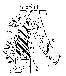
Figs. 1, 2 and 2A illustrate a primary conveyor belt
cleaner 120 for cleaning a conveyor belt 21 of width W. Belt
21 is driven in the direction of arrow A, Figs. 1 and 2,
around the longitudinal axis L, Fig. 1, on the surface of a
head pulley 70.
Belt cleaner 120 comprises two shafts 22A and 22B that
are aligned with each other and that are joined by an
elongated support 24. Support 24 preferably comprises a
rigid metal sleeve that extends transversely of belt 21 in
spaced relation to the outer surface to be cleaned. Support
24 has a length L1 approximately equal to the belt width N;
they are shown equal in Fig. 1. The left-hand end of shaft
22A, Fig. 1, is journalled in a bearing 25 supported by a
fixed frame (not shown). Inwardly from bearing 25, shaft 22A
is affixed to the elongated sleeve or support 24 by suitable
means (not shown). If desired, the shaft segments 22A, 22B
may be a continuous shaft through the interior of support
sleeve 24.
The right-hand portion of shaft 22B, Fig. 1, extends
through another bearing 28 mounted in the fixed frame (not
shown) that affords general support for primary conveyor
cleaner 120. Bearing 28 is connected to a flange 29 on a
torsion tube 31 that is part of a torsion bias mechanism 30.
Another flange 32 on the other end of torsion tube 31 is
connected to a collar 33. Collar 33 is connectable to the
2096561
- outer end of shaft 22A through an angularly adjustable
connection comprising a shear pin 34.
As shown in Fig. 2, there is an inverted T-shaped
mounting member or guide 42, shown as formed by two angle
irons, affixed to support sleeve 24. Mounting member 42
preferably extends for the full length of sleeve 24. Guide
42 is also a blade reinforcement, as described hereinafter.
Guide 42 may be welded or otherwise firmly secured to
transverse support 24. Noreover, guide 42 may be continuous
or intermittent along sleeve 24, depending on the blade
construction employed.
In primary belt cleaner 120, a single, unitary scraper
or cleaner blade 136 is mounted directly on support 24. As
shown in Fig. 1, blade 136 may have a length approximately
equal to the length L1 of support member 24 and the width W
of belt 21. Alternatively, a plurality of blade segments
(not shown) may be utilized, abutting each other, with the
same overall length.
Scraper blade 136 has a short base wall 151 and two
substantially longer side walls 155 and 156; see Fig. 2.
Thus, blade 136 is generally triangular in cross-sectional
configuration. Walls 155 and 156, however, are curved, in
the same direction, and blade 136 is mounted on support 24 so
that the one side wall 156 of the blade that faces belt 21
and head pulley 70 is concave toward the belt and pulley.
With that alignment the other wall 155 of blade 136 is
2096561
concave outwardly of pulley 70 and belt 21. In the
preferred construction for primary blade 136, the outer
(concave) wall 155 of blade 136 projects inwardly toward wall
156 from a break line 157 (Figs. 2 and 2A).
Break line 157 is preferably somewhat rounded, affording
a smooth corner which joins the convex wall 155 to a second,
short transition wall surface 158 that extends to the upper
edge of the concave wall 156. The intersection of transition
surface 158 of wall 155 with the inner concave wall 156
defines the scraping edge 137 of blade 136. That is, surface
158 affords a truncated or curtailed transition of wall 155
to wall 156 in blade 136. With this blade configuration, the
outer end or tip portion 138 of blade 136 is thicker than
would have been the case if the wall 155 did not have the
break line 157 ending in the inwardly directed transition
surface 158. As explained below, the tip portion 138 in a
new, unworn scraper blade provides a significant improvement
during inception of blade operation, particularly during
movement of a mechanical belt splice past cleaner 120.
Primary blade 136 has a rigid metal reinforcement 139
molded into the base wall 151 of the blade. Reinforcement
139 is of inverted U-shaped configuration, affording a
receptacle 153 facing outwardly of the base wall 151 of the
blade. Receptacle 153 receives the upwardly projecting
portion of guide 42, so that the guide serves as a
reinforcement for the base portion of blade 136 in addition
20~6~61
- to providing a guide to align the blade on support 24.
Inasmuch as primary cleaner 120 works on the surface of belt
21 in that part of the belt that is in contact with head
pulley 70, there is no need to provide for varying angular
configurations other than an incremental and instantaneous
adjustment in angular position of the blade which is absorbed
by the torsion bias mechanism 30, as explained below. On the
other hand, support 24 is provided with a torsion bias device
such as the device 30, Fig. 1, to bias support member 24 in
the direction of the arrow X, Figs. 1 and 2.
The wear pattern for blade 136 of primary belt cleaner
120 is illustrated in sequential views in Figs. 3A-3D. Fig.
3A shows blade 136 at a position 136A approximately
corresponding to that illustrated in Fig. 2. To indicate
relative disposition of blade 136, a plane P is shown in
Figs. 2, 3A, 3B and 5 and is defined as a horizontal plane
which includes the longitudinal axis L of head pulley 70.
Blade 136 is shown well below plane P in Figs. 3A-3D, for
purposes of illustration.
At the outset, as in Fig. 3A, there is little or no wear
on the scraper blade; blade 136A is assumed to be new. Figs.
3B, 3C, and 3D show successive stages in the wear life of the
primary cleaner blade, with additional increments of wear of
the blade illustrated by the blades 136B, 136C, and 136D. As
shown in Fig. 3D, blade 136D is worn to the point at which it
requires replacement. These figures also illustrate the
2096561
substantial changes in angular alignment between the blade
and the belt 21 on the surface of head pulley 70.
In all embodiments of the present invention, the shape
of the scraper blade, with elongated curved walls tapering
toward each other from a short base wall, allows for longer
wear than with previously known constructions. With
increasing wear, there is less tendency for the blade to bend
or "give" in response to minor disturbances, a characteristic
of this construction that increases blade longevity. On the
other hand, the blade shape allows for the use of appreciably
"softer" and more resilient blade materials than with
previously known curved blades. As a consequence, belt
cleaners using the blade shape of the present invention can
accommodate mechanical belt splices and other like belt
obstructions better than heretofore known belt cleaners, and
last longer in many applications. Moreover, the shape of
blade 136 permits use of plural primary cleaners in a single
system as discussed in connection with Fig. 5.
Thus, the shape of blade 136, with its converging curved
walls 155 and 156 and the thickened tip portion 138 in an
unworn blade, provides a resilient spring back feature when
the blade end section 138 and scraping edge 137 undergo
stresses which arise from debris adhered to the belt or from
a mechanical belt joint. This feature continues to play a
role in blade operation even after substantial blade wear, in
part because a relatively soft, more resilient resin can be
20~61
- and is used in molding blade 136. This can be quite
important for any belt 21 on which debris has adhered and
which is especially difficult to scrape and for any belt 21
that employs mechanical splices.
Figs. 4A-4D are similar to Fig. 2; they afford a cross-
section view of belt 21, head pulley 70, and blade 136 as a
mechanical joint 180 in belt 21 moves past the scraping edge
137 of blade 136. The belt splice 180 comprises an inner
plate 182 and an outer plate 184 located on opposite sides of
two segments 2lX and 2lY of conveyor belt 21. The two
segments 21X and 21Y of belt 21 are joined by the mechanical
joint 180 to provide a part of the endless belt used in the
conveyor. There may be several such mechanical joints 180 in
belt 21; the number of splices depends to some extent on the
length of the conveyor belt. Plates 182 and 184 are secured
to each other by pins or rivets 186 between the plates; pins
186 also go through the ends of belt segments 2lX and 2lY.
Thus, plates 182 and 184 of mechanical joint 180 sandwich the
two ends of the belt 21 between them to retain the belt ends
together.
Figs. 4A-4D show successive intervals of time which
mechanical joint 180 passes the scraping edge 137 of a newly
installed, unworn blade 136. Of course, the duration of
those time intervals depends upon the speed of movement in
the direction of arrow A and hence cannot be stated
precisely. This particular example, that of a mechanical
2096~6 1
- joint meeting the scraping edge of the resilient blade, is
used because it occurs at least once and usually several
times for each revolution of belt 21 around the conveyor.
However, operating principles featured in the discussion of
mechanical joint 180 are equally applicable in the case of
adhered debris or any other anomaly which may occur in the
smoothness or flatness of belt 21.
Fig. 4A shows the position of a new blade 136 and its
scraping edge 137 as joint 180 first contacts the scraping
edge 137 of the blade. The outer surface of belt 21 is
displaced away from the outer surface of head pulley 70 to
accommodate the increased thickness of belt 21 caused by
splice 180. Because of the resilience of the blade
material, scraping edge 137 and a local portion of the blade
tip 138 are first bent toward the left, outwardly from the
normal blade position, Fig. 2. At this point (Fig. 4A) the
main body of the blade 136 has moved a short angular distance
against the tension, in direction X, from the torsion bias
mechanism 30 (Fig. 1). The angular displacement of the
support 24 relative to a normal or index position, line P',
is indicated as angle a in this and the succeeding views
(Figs. 4B-4D). Angle a indicates the difference in angular
position of support 24 from that normal or index position,
Fig. 2.
In Fig. 4A, angle a is approximately 10. In a
preferred actual installation, the scraping edge 137 would
~ 2096~61
contact the head pulley 70 some small distance (e.g., two
inches) below the plane P (Figs. 2, 3A, 3B). Plane P' is
parallel to plane P. Accordingly, the contact point of the
scraping edge 137 and belt 21 on head pulley 70 occurs
beyond the point where the belt 21 has begun to return toward
the right in the direction of rotation A.
Fig. 4B illustrates the next instant of the belt cleaner
operation; joint 180 has rotated to a point just a short
distance lower than that shown in Fig. 4A. Because of the
elasticity of the material of blade 136, and due to the shape
and dimensions of blade 136, the scraping edge 137 of the
blade maintains its position relative to the outer plate 184
of joint 180. As the outer plate 184 of joint 180 rotates
with the head pulley in the direction A, the scraping edge
137 of blade 136 is compressed downwardly; the main body of
blade 136 does not come under tension and is not thrust
radially outwardly from its position relative to the surface
of the head pulley 70 to any appreciable extent. Rather,
blade 136 bends slightly. Thus, in Fig. 4B the angle a
changes only infinitesimally; it is approximately 10l'.
Fig. 4C illustrates the instant when the resiliency of
blade 136 causes its scraping edge 137 to be released by the
edge of the upper joint plate 184 and to spring back to an
extended position. The configuration of the main body of
blade 136 is bent as it returns toward its normal, non-
stressed configuration. At this point belt 21 is greater in
~1 ~ 2096~61
thickness, at joint 180, due to the presence of plates 182
and 184. This greater thickness causes blade 136 to rotate
somewhat farther against the angular force X applied by the
torsion bias mechanism, in order to compensate for the
difference in angular position. However, the main body of
blade 136 has not yet experienced the effects of the outward
motion of the blade end section 138. Thus, the base of the
blade 136 maintains the "bowed out position (Fig. 4B); angle
a in Fig. 4C is approximately 118'.
Fig. 4D illustrates the relationship of the belt cleaner
components as the mechanical position of the joint 180
continues its movement past the scraper blade edge 137. In
this figure, blade 136, and especially the base, experiences
the full effect of the sudden release of compressive tension
which was caused by the downward displacement of the end
section 138. Thus, the base of the blade 136 indicates only
a slight angular displacement because the base of the blade
is undergoing the overreaction of the resilient springing
force of the blade with the release of tension compressive
force on scraping edge 137, which is suddenly set free.
Accordingly, although the end section 138 of blade 136 is
angularly displaced more than normal, angle a is back to
about 10l', as in Fig. 4B. Once splice 180 clears scraping
edge 137, blade 136 and support 24 return to their initial
positions, Fig. 2.
16
20~S~I
~ Figs. 4A-4D illustrate a significant feature and
distinct advantage of the inventive blade. The combination
of a relatively soft" resilient material as the constituent
material for blade 136 and the configuration and placement of
blade 136 and its support mechanism, together with the
continuous resilient bias X from mechanism 30, provide an
ability to maintain the scraping edge 137 of the blade 136
flush against the surface of the belt 21 even when
encountering anomalies, such as joint 180, in the belt
surface. Moreover, the transition blade surface 158 is
angled relative to walls 155 and 156 of blade 136 so that any
material engaging surface 158 is deflected from blade 136.
Thus the shape, dimensions and configuration of the blade,
the support and the head pulley provide a most efficient
scraping function for the cleaning system, and withstand
mechanical splices and other anomalies without damage to the
scraper blade.
Fig. 5 illustrates another embodiment of the cleaning
system of this invention. The system shown in Fig. 5
includes a primary cleaner 120, as described above, with its
support 24 biased in direction X, and blade 136 with its edge
137 engaging a conveyor belt 21 passing over a head pulley
70. There is no secondary cleaner of the conventional kind.
Instead, the system of Fig. 5 comprises a second primary
cleaner 120' having a blade 136' with its tip edge 137'
engaging belt 21. The components 136', 137', and 24' of
209~5~1
- cleaner 120' may have the same length, shape and dimensions
identical of the corresponding components of belt cleaner
120. Indeed, belt cleaner mechanism 120' is preferably a
duplicate of cleaner 120.
The blade 136' of the second primary cleaner 120' is
positioned further along the path of the belt 21, beyond
blade 136 of cleaner 120, in the direction A of conveyor
belt movement. For an unworn blade 136, the preferable
distance from plane P down to the contact point of the blade
scraping edge 137 with belt 21 is approximately two inches.
The second scraper 120' may be mounted to contact belt 21
quite close to cleaner 120. For a blade height of six
inches, therefore, the distance between plane P and the
contact point of scraping edge 137' of the secondary cleaner
blade 136' may be approximately eight inches. Of course,
substantial variation is permissible, depending in part on
the diameter of head pulley 70.
The close relative positions of blades 136 and 136'
(Fig. S) provides for a more efficient belt cleaning function
than usual with a more conventional primary and secondary
belt cleaner configuration. The uppermost blade 136 usually
has an angle of incidence which approximates a vertical
tangent to the cylindrical surface of the head pulley. Even
after blade 136 has become worn to a degree where the
transition surface 158 is no longer on the blade (see, for
example, blade 136B, Fig. 3B), the angle between the head
2096~61
~ pulley 70 and the inner blade wall 15S remains an obtuse
angle.
Moreover, the inwardly curved concave configuration of
the outer blade wall 156, relative to the base wall 151,
permits blade support 24 to be disposed close to the head
pulley 70 without interfering with operation of the
conveyor. This is advantageous because it enables the blade
to maintain an obtuse angle between its outer wall 156 and
the head pulley and belt surface even after considerable wear
of the blade; see blades 136C and 136D in Figs. 3C and 3D
respectively.
Referring again to Fig. 5, because the blade 136' of the
second primary cleaner 120' is disposed at a point further
along the path of arrow A in which the belt 21 is driven,
that blade 136' is disposed at an even greater angle to the
vertical than is blade 136. Thus, if any debris continues to
adhere to belt 21 after it has passed blade 136, the
secondary cleaner comprising blade 136' will be more apt to
dislodge and remove the debris because of the added force
resulting from gravitational pull at the point of engagement
of edge 137' with the surface of belt 21. Blade 136', which
cleans the outer surface of the belt across its whole width,
provides an efficient second cleaning capacity for the
system. In particularly adverse applications conveying
material that adheres strongly to belt 21, a blade 136' may
be used in conjunction with a secondary cleaning system of
` 20965~1
~ the kind described in application Serial No. 07/877,229 filed May 1, 1992.
For blades 136, polyurethane is the preferred resin,
though other resilient resins can be used. Polyurethane in a
durometer range of 75 to 85 Shore A is preferred. For the
rigid elements (support 24, guide 42, etc.), metal is
preferred, though rigid resin or laminate members could be
employed in some instances, as for reinforcements 42 and 139.
In all of the embodiments described above, blade 136 is
shown as one integral, continuous member having a length L1
approximately equal to belt width W. It should be
understood, however, that the blade 136 may be assembled as a
sequence of shorter blade segments, as shown in the
applicant's earlier patent No. 4,533,036. Reference to a
blade in the appended claims is intended to include such an
assembly of shorter blade segments.
; 20