Note: Descriptions are shown in the official language in which they were submitted.
g6698
OPTICAL TF~ANSMITTER AND RETURNER
This invention relates to a device for llallc,lllil~illg and returning light and an
apparatus for and method of marlufacture thereof. More particularly, this invention is
concerned with a device wherein a retunner or reflector is embedded in the end of an
elongate light transmissive member made with an apparatus and by a method whereby
the retumer and the elongate light l.c"~",~ member are aligned along an axis in
a tube wherein they âre heated and urged together.
U.S. Patent No. 5, 047,208 discloses an optical sensor fcr blocd gâs
measurement comprising a pH sensitive absorption dye between the end of an opticai
fiber and a minror. The mirror is located by a tubo which carries the mirror spaced from
and coaxially aligned with the fiber wherein the dye is located in the space.
U.S. Patent No. 5,005,676 discloses an optical sensor for blood gas
measurement capable of measuling pH, pO, and pCO~ with light absorption dyes
between the ends of an optical fiber and a reflector unit.
U S. Patent No. 5,047,627 discloses a multi-analyte sensor comprising optical
fibers with associated indicators crranged in a sheath with light reflectance material
disposed adjacent to the indicators.
U.S. Patent No. 4,889,407 discloses an optical waveguide sensor for
d~tl",i"i"g an analyte in a medium which sensor comprises an optical waveguide
having a plurality of cells arranged in an array which substantially covers the cross
sectional area of the waveguide, each of the cells containing an indicator sensitive ~o
the analyte.
In accordance with the l~resent invention there is provided a device for
l-c":,",illi"g and returning light C~ i"~.
an elongate light llall~ member having an axis aiong the longitude
thereof, which elongate light 1, cl1SI ";s~ivc member is a flexible polymer fiber having first
and second ends substantially normal to the axis for passing light ~ . " and
a returner shaped and sized to fit the second end with a face positioned
forretunninglightl,c,~s,,,illt!~ithro~lghtheelongatelighttransmissivemembertheface
disposed substantially nonmal to the axis and embedded within the second end.
Theinventionalsoprovidesamethodformanufacturingadeviceforl,c,,~,,,illi,,g
and returning light, which device comprises an elongate light ll~)s", \~ flexible
member having an axis along the longitude thereof, which elongate light ~lall~llli'::,;, ~e
.
-2- ~0~698
member Is a flexible polymer fibel having first and second ends substantially normal to
the axis for passing light therebetween; and a returner shaped and sized to fit the
second end with a face positioned for retuming the light llalls",i~l~d through the
elongate light llall:,llli:,s;~c memlber, which returner has a melting point substantially
higher than the melting point of the elongate light l, ~ ,~" ~ h~ member, the face being
disposed substantially normal to the axis and embedded within the second end, which
method comprises the following steps:
placing a tube having a cross-sectional shape similar to that of the
elongate light ll al la" lis~ memt~er along the axis, the tube being sized to receive the
elongate light l,c":,",;~ :;c meml~er for telescopio conjugation therewithin;
aligning the returr~er along the axis with its face substantially normal
thereto for placement upon the s~cond end of the elongate light ll a~ c member;
s~-~pi~ y urging the tube, the elongate light transmissive member
and the returner wlth the tube corixially about the elongate light l~ ~s" 1i65~VC member
and wlth the returner against the second end;
heating the tube, the elongate light llc~ is_;~c member and the
returner, and
~:"~L,eddi"g the rsturner within the second end without melting or
deforming the tube.
The invention further provides an apparatus for manufacturing a device for
transmitting and returning light, v~hich device comprises an elongate light ll al l~
flexible member with an axis along the longitude thereof, which elongate light
lla,ls",i~:,:Je member is a flexible polymer fiber having first and second ends
substantially normal to the axis for passing light l~ 2n, a returner shaped and
sized to fit the second end with t~ face positioned for returning a substantial portion of
the light llall~llli~l,:d through the elongate light llallSIIli~ C member, the returner
having a melting point substanti~lly higher than the melting point of the elongate light
Il Gl 1511 lia~ ~'C member, the face disposed substantially normal to the axis and embedded
within the second end, the elongate light transmissive member and the returner each
having cross sections of a similar size, and a holder placed substantially parallel to the
returner to secure the embedded returner at the second end; which apparatus
comprises a tube having a cross-sectional shape sirnilar to that of the elongate light
llall~ ;s~.v~ member posltioned along the axis, the tube being sized to receive the
~096~98 64680-685
elongate light transmissl-~e member for telescopic conjugation
therewithin; means for aligning the face along the axis
substantially normal thereto for placement upon the second end
of the elongate light trarlsmissive member; means for telescopic-
ally urging the tube, the elongate light transmissive member and
the returner with the tube coaxially about the elongate light
transmissive member and wi th the returner against the second end;
and a heater placed about the tube, the elongate light trans-
missive member and the returner thereby allowing the returner to
be embedded within the second end without melting or deforming
the tube.
The elongate light transmissive member in the device
according to the invention preferably is a clad polymer fiber
with a longitudinal axis ~;~ith first and second ends substantially
normal to its axis . The f iber passes light between the ends .
The elongate light transmissive member preferably has a core of
polymethylmethacrylate polymer and a cladding of fluorinated
polymer .
A returner, i.e., a mirror, light emitter, fluorescor,
absorber, reflector, scatterer or a combination thereof, prefer-
ably shaped and sized to fit the second end has a face positioned
for returning substantially all of the light transmitted through
the elongate light transmissive member. The returner preferably
has a- melting point which is substantially higher than the
elongate light transmissive member and is disposed with its face
normal to the axis and embedded within the second end. The elongate
light transmissive member and the returner each preferably has a
substantially circular cross-section each with a substantially
-3a- 2~3~698
64680-685
equal diameter. Preerably a holder is placed substantially
parallel to the returner to secure the embedded returner at the
second end and terminate the second end with a polymer
encapsulating the returner and the holder completing the iber.
The method acco]-dlng to the invention preferably
includes the steps of aligning the returner along the axis with
its face substantially no]^mal thereto ior placement upon the
second end of the elongate light transmissive member, and
telescopically urging the elongate light transmissive member
and the returner together with the tube coaxially about the
elongate light transmissive member and with the returner against
the second end. The step of heating the tuber the elongate light
transmissive member and t~le returner embeds the returner within
the second end without melting or deorming the tube. Applying
the holder with the heated vacuum pickup to the second end
secures the returner.
2~9~698
In the apparatus according to the invcntion, the tube is sized internally largerthan the elongate light ~, al ,al "ia~ e device to permit insertion and removal of the device
for llalls",i~i"g and retuming ligllt from the tube. The tube preferably is made of a
relatively nonconductive material. The tube and elongate light llallallli~_:v~ member
conjugatQ ~ P~CO~ IIY and pre~erably are circular in cross-section.
The apparatus includes means for ~ s~ol,i( "~ urging the elongate light
1,~,:"" ;;:~ member and the retumer together with the tube coaxially about the
elongate light llallal,,ic,_:a. member and with the returnerfor placement of the retumer
normal to and against the second end. A heater placed about the tube, the elongate
light transmissive member and the returner allows the returner to be embedded within
the second end without melting or deforming the tube. A vacuum pickup holds the
returner in alignment with the axis during placement on the second end.
Preferred embodiments o ~ the invention will be more particularly described withreference to the accompânying drawings in which:
Figure 1 is a perspective view of a device for 1, al lalllilLil ,9 and returning light;
Figure 2 is a side elevatiol~ in (partial) cross-section of the device of Figure 1 as
would be seen if the cross-section were taken along line 2-2 in Figure 1;
Figure 3 is an exploded perspective view of an apparatus for the manufacturing
of a device showing the assembly of a returner thereto;
Figure 4 is a side elevation in partial cross-secbon of the apparatus of Figure 3
as would be seen if the cross-section were taken along line 4-4 in Figure 3;
Figure 5 is an exploded perspective view of an apparatus for the application of
the holder during the manufacture of the device; and
Figure 6 is a side elevation in partial cross-section taken along line 6-6 of Figure
5 showing the tube, pickup and heater during assembly of the holder to the elongate
light ll a~ ;a~ member to embed the returner.
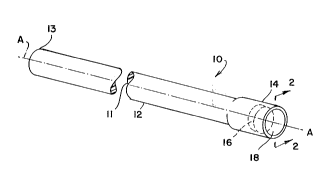
The embodiment illustrated in Fig. 1 is a device 10 for ~, al lal "illi"g and relurning
light o~" ,~ .il ,g an elongate light l, al~s" ,ia~ivc flexiblQ member 11 in the form of a clad
polymer 12. The elongate light ll a" ""ia~hr~ flexible member 11 has a longitudinal axis
~A~ and a first end 13 and a second end 14 that is substantially normal to its axis "A-.
The elongate light transmissive member 11 is of a polymer capable of passing light
between the first end 13 and the second end 14.
Z O 9 6 6 9 8 64680-685
Figure 2 is a sLde elevation in ~partial) cross-section
of the device Qf Figure 1 as would be seen if the cross-section
were taken along line 2-2. The elongate light transmissive
member 11 pre~erably has a core 15 of polymethylmethacrylate
polymer and a cladding of f luorinated polymer . A returner 16,
i.e. a mirror, light emitter fluorescor, absorber, reflector,
scatterer, gas permeable device, or a combination thereof, is
shaped and si2ed to fit the second end 14 and with a face 17
positioned for returning a substantial portion of the light
transmitted through the elongate light transmissive member 11.
The returner 16 is .in the pre:Eerred embodiment a piece of medical
grade stainless stePl polished to be an PYrPl 1 Pnt ref lector . The
returner~ 16 is stamped to Lnake a circular disc from a thin sheet
of such metal and so has a melting point which is substantially
higher than the elongate light tr~n~i ss~ve member 11. The
returner 16 is disposed with its face 17 normal to the axis "A"
and the returner 16 is embedded within the second end 14.
In a preferred embodiment the elongate light transmissive
member 11 and the returner 16 each have a substantially circular
cross-section with the diameter of the returner 16 substantially
equal to the diameter of tlLe elongate light transmissive member
11. The returner is preferably positioned about 1 to 2 diameters
~rom the second end 14. A holder 18, when necessary or desirable,
is placed substantially parallel to the returner 16 to secure the
embedded. returner 16 at the second end 14. The holder 18
terminates the second end 14 so that polymer encapsulates the
returner 16 when the holder 18 completes the fiber.
-5a- 2ID9~i6g8
64680-685
Figure 3 is an exploded perspective view of an apparatus
19 for manufacturing a device by assembly of the returner 16 into
the device 10. The apparatus comprises a tube 20 having a cross-
sectional shape slmilar to that of the elongate light transmlsslve
member 11. The tube 20 is positioned along the a~is "A" and has
a cross-sectional shape slmllar to but lnternally larger than the
device 10 for permitting lnsertion into and removal of the device
from the tube 20. The elongate light transmissive member 11 is
recelved for telescopic conjugatlon within the tube 20. The
tube 20 is in the preferred embodiment of a relatively non-
conductive material such ~lS glass. The preferred cross-sectional
shape of tube 20 is circu] ar.
Figure 4 is a side elevation in partial cross-section
of the apparatus of Figure 3 as would be seen if the cross-section
is taken through the tube 20 and a heater 22 of the apparatus 19
when assembling the returner 16 to the elongate light transmlssive
member 11. The apparatus 19 includes means for telescopically
urging 21 the elongate
-6- 209~698
lightl,al~:,."is~:v~member11 andtheretumer16toge~herwhilethetube20iscoaxially
about the elongate light llall:,lll .~ member 11 when the returner 16 is broughtagainst the second end 14. The ~leater 22 is placed about the tube 20 and the second
end 14 of the elongate light llal,,",' '~c member 11 and the returner 16, which are
within the tube 20, thereby allowlng the retumer 16, under the force of the urging, to
be embedded wlthin the second end 14 without melting or deforming the tube 20. The
second end 14 is shown in Figure 4 with a slightly enlarged distâl diameter 23 which
is the direct result of the heat apl~lied through the tube 20.
The diametrical expansion resulting from the heat also prepares the second end
14 to receive the retumer 16 by softening the polymer. A vacuum pickup 24 aiigned
along the axis ~A~, is inserted ir~to tube 20 wlth retunner 16 held by differential air
pressure on the end thereof that faces second end 1~. While a specific " ,e~:l ,a"i~", is
not shown and although the n~eans for l~-les~ AIly urging 21 is illustrated as
ACSo~`iAt~d with the vacuum pickup 24, it should be ~,upl~,ial~d that the means for
t~ c~,pi~ ~lly urging 21 the elon~ate light l, al~l, lias!~ member 11 and the returner 16
together may employ a pressure sensitive drive applied against either the elongate light
llal,sr";ss~ member 11, the retl~rner 16 or both. Consequently, the heated second
end 14 and the face 17 of the ret~lrner 16 are pressed against each other to embed the
returner 16 in the second end 14.
Figure 5 is an exploded perspective view of an apparatus 25 for application of
the holder during manufacture of the device 10. The apparatus 25 includes vacuumpickup 24, means for l~-les~ lly urging 21 and tube 20. The apparatus 25 for
'. F n of the holder 18 is different as shown in Figure 5 wherein the placement of
heater 22 is about the vacuum pickup 24. The vacuum pickup 24 in axial alignmentwlth axis .Au inserts the holder 18 into the tube 20 as shown in Figure 6 which is a side
view in partial cross-section taken along the line 6-6 of Figure 5. Therein it is shown
that the tube 20, vacuum pickuF1 24 and the heater 22 are in line on axis "A- during
assembly of the holder 18 to the elongate light transmissive member 11.
The holder 18 is placed substantially parallel to the embedded retumer 16 to
secure the embedded returner 16 at the second end 14. The holder 18 temminates the
second end 14 and enc~rs~ the returner 16 when the holder 18 completes the
elongate light llall .ll~ c member 11.
7 2~96698
The method for manufactl~ring Ihe device 10 includes the step of placing the
tube 20 having a cross-sectional s hape similar to that of the elongate light I, a~
member 11 along the axis A. The larger intemal diameter of the tube 20 permits
Tnsertion and removal of the device 10 from the ~ube 20 before and a~ter manufacture.
5 The tube 20 receives the elon~ate light ~lall~lll;S:.~C member 11 for telescopic
conjugation therewithin.
The method also preferably includes the steps of aligning the retumer 16 alcng
the axis 'A' substantially with its ~ace 17 nonmal thereto for placement at the second
end 14 of the elongate light ~lal, ""' ,v~ member 11. The elongate light llal /~
10 member 11 ând the returner 16 together with the tube 20 coaxlally about the elongate
light ~, al 1~1 1 1' ' .'6 member 11 are then urged against the second end 14. The tube 20,
the elongate light transmissive member 11 and the re~umer 16 are then heated to
embed the returner 16 within the second end 14 without melting or deforming the tube
20. AT~plying the holder 18 with a heated vacuum pickup 20 to the second end 14
15 secures the returner 16.