Note: Descriptions are shown in the official language in which they were submitted.
f i 4 ~; ~
IMPROVEMENTS RELATING TO THE LINING OF PIPELINES aR
PASSAGEWAYS
This invention relates to the lining of pipelines and
passageways, and in particular concerns the lining of such
pipelines or passageways, with a tube or lining of thermo-
plastic material which is of a nature such ~hat it is
folded longitudinally in order to reduce its overall
dimensions, to enable the lining tube to be inserted into
the pipeline or passageway, and subsequently can be re-
expanded up to the pipeline or passageway size so as to
line the surface thereof, which constitutes its final
form.
:'
In order to enable the plastics material to go through
these stages, it needs to be heated so that it will be soft
when it is in position in the pipeline or passageway, but
before being expanded up to the pipeline or passageway
size.
There are already a number of methods for lining pipelines
or passageways using thermo-plastic lining pipes, and one
such method comprises extruding ~he plastic lining pipe
followed by the-immediate folding of same, followed by
cooling and coiling onto a storage drum. -The storage drum
is taken to the site where the pipeline or passageway,
which usually will be underground, has to be lined, where
at the folded and coiled lining pipe is unwound, and is
heated to soften same, and it is fed into the pipeline or
passageway down a man-hole and then along the pipeline or
pas~ageway to be lined.
When ~he hot folded lining tube is in position, its
interior is pressurlsed to expand same onto ~he pipeline or
passageway surface, followed by cooling of the lining pipe
so that it will solidify in place and remain in place when
the inflating pressure ie removed.
'' :~ .: .:
- ' ' . . :' '
Other sys~ems are known but generally speaking they
follow the lines of the me~hod described above. The
present invention is also concerned with the insertion of a
thermo-plastic pipe into a pipeline or passageway and, with
the expansion of the thermo-plastic pipe, when hot, onto
the pipeline or passageway surface but the present
invention provides that the method can be used for the
- lining of extremely long lengths of pipeline or passageway,
the known methods being limited to the length o~ coiled
10 pipe which can be taken to site.
In accordance with the general method of the invention, the
~hermo-plastic lining pipe is ex~ruded on site in a
substantially vertical downwards direction into a man-hole
15 and the extruded pipe is guided down the man-hole and into
the pipeline or passageway to be lined, whilst the exterior
of the extruded lining pipe is kept warm and the pipe
therefore soft by virtue of heating fluid surrounding the
extruded lining pipe, and the lining pipe either being
20 extruded in a folded form so th2t it is of reduced overall
dimension enabling it to be passed into the pipeline or
passageway, or being folded or formed after extrusion into
such reduced size, and the soft, hot and folded extruded
lining pipe being expanded when in the pipeline or
25 passageway onto the pipeline or passageway sur~ace and
eventually being cooled so as to remain in position on such
surface.
The extruded lining pipe may be applied to the pipeline or
30 passageway surface by being everted onto such surface, the
pipe expanding as it everts, or al~ernatively it may be
pulled into position, until it extends for the full length
of the pipeline or passageway to be lined. When it reaches
such posi~ion i~. may be expanded by introducing fluid under
35 pressure into the interior of the linins pi~e either
directly or by everting an expansion tube into the lining
pipe.
- . . ' ' ' '
. - - : - : . .- - - - :
.. -. . : : -
:
. - . , . . - ~ .:
- . ' ' ' ~
.
.
- ' ' : . , :
..
~'"0~ PC~/G~91/019~4
-- 3
It is preferred that the exterior of the extruded
lining pipe in addition to being kept warm by means Or
heated fluid, will also be kept under pressure by said
fluid in order for example to keep the lining pipe in the
said folded condition.
To assist in the pulling of the lining pipe into the
pipeline or passageway, a pull-rope may be fed ~hrough the
extruder so as to emerge in the centre of the extrudate
which, after folding, engages the central rope, and is held
suitably thereto by virtue Oe the friction which arises as
a result of pressuring ~he exterior of the lining pipe by
the said heated fluid.
By virtue of the said invention, theoretically infinitely
long pipelines or passageways can be lined, and the lining
pipe thickness can be accurately controlled. Additionaly,
the manner in which the pipe is folded can be controlled ~`
and varied with ease. It is particu~arly suitable for
example to old the pipe so that in its reduced outer size,
it will define a s~ar configuration. Such folding enables
the lining pipe to travel readil~ around bends and curves
in the pipeline to be lined~
Any suit~ble thermo-plastic may be used for the lining
pipe, such material to include p.v.c. or any of the
polyolefins.
Because an extruder which extrudes vertically downwards is
utilised, it is also po~sible ~to feed into the centre of
-the ex~ruder a fabric tube which forms reinforcement for
the interior of the extrudate, and if the extruded tube i~
eventually everted inside the pipeline or passageway, the
reinforcement tube will be presented to the pipeline or
passageway surface.
This fabric layer may form a useful anchoring means if the
- . ~
~ ~ o-7 /f)OQ~ R01 /~17 00 1
~,
extruded pipe is to be anchored to the pipeline or
passageway suface, for example using a curable synthetic
resin as adhesive or bonding medium.
An embodiment of the present invention will now be
described, by way of example, with reference to the
accompanying diagrammatic drawing, wherein the single
figure shows one method of realisation of the present
invention.
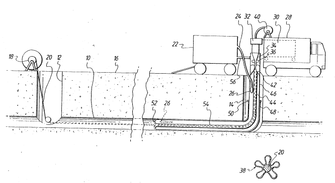
Referring to the drawing, an underground passage (10) to
be lined in accordance with this embodiment of the
invention extends between a pair of man-holes (12) and (14)
extending from the passage (10) to ground level (16).
At ground level adjacent the man-hole is a winch (18), the
purpose of which is to winch a pull-rope cable or the like
(20) to assist the lining operation as will be described.
At the other man-hole (14) at ground level there is a
generator and boiler unit (22) for electricity supply and
supply of hot water whiçh is in fact ejected through an
outle~ water pipe (24) to a head (26) whose function will
be described hereinafter.
; -
Also at the man-hole 114) is an operational vehicle (28)
housing an extruder (30) which supplies plastic material to
a cross-head extruder (32) as shown to exude an extrudate
(34) in a vertically downwards manner. The ex~rudate is in
the form of a circular pipe which is formed into folded
configura~ion by folding rollers (36), so that the
extrudate is for example formec into the star configuration
shown at (38). The thus formed axtrudate is folded around
a central rope (20) which extends entirely through the man-
hole and the passageway (10) to be lined and onto thewinch (18). The rope (20) is fed from a supply (40)
carried by the vehicle and passes through the centre of the
. . . : '
- - ,.. : : .: . :- . . : :
.
: . . , :: . - , : ,:
. . . . . . . .
::
.. . .
, . . . . . . .
_ ~ _ P~/(~1~91 /n1994
extruder cross-head (32).
An orifice valve arrangement (42) enables ~he downstream
chamber (44) which is defined by a pipe (46), and the end
of the extradate (48) which has been inverted and attached
to ~he pipe (46) by a clamp (50), to be pressurised with
water supplied from the head (26).
It will be appreciated that when the extrudate is initially
extruded, the leading end is turned upon itself and ~.
connected to the end of the pipe (46) at location (50), and
hot water is supplied through the head (26). Head (26) is
of a type which will be self propelled in that the hot
water issues from the rear of the head, and therefore the
15 head is forced forwards as far as possible so that as shown
on the drawing as the extrudate everts in the region of ~he
everting face (52), so the head (26) remains close to such
face and supplies hot water to assist in the eversion, and
also ~o keep the inwardly travelling portion (54) of the
2~ extrudate in a soft condition so that it will expand freely
at the evertin~ face ~52) as that face travels along the
passageway (10). ~;
The valve (42) serves ~o maintain the pressure in the
chaamber (44), but if there is any excess pressure water is
in fact bled upwardly through the valve (42), and will
return to ~he boiler via the return line (56).
The extruding operation will be discontinued w~en the
everting face (52) is approximately halfway alon~ the
passa~eway (10), so that the trailing end of the extrudate
will arrive in the region of the man-hole (12). Some
means may have to be provided in order to seal the trailing
end of the extrudate so that the pressure can be maintained
inside the extrudate and the hot water can be replaced wi~h
cold water in order ~o cure the extrudate material which is
thermo-plastic in nature.
- ' : , -
,, : - ::
.
,
7 /O~Q t' l~!rl?01,~
- 6
By virtue of keeping the inwardly travelling portion (54)
under heat and pressure, so there will be no tendency for
the folds of the extrudate to unfold prema~urely, and
furthermore the ex~rudate will be pressed firmly into
frictional contact with the rope (20) so that any pull in
~he rope will clearly assist the eversion process.
The extruda~e may be of any suitable material such as
p.v.c. or a polyolefin~
The use of the rope ~20) can be employed to assist in the
control oE the ~peed o~ extrusion.
Additionally, it is possible to feed other members into the
cross--head (32), such other members comprising for example
fabric tu~es which will eventually be everted with the-
extruded lining tube so as to lie between the tube and the
passageway surface. Such fabric tubes may be of assistance
when for example synthe~ic resin is applied to the everting
face or to the wall of the passageway (10) in order to
anchor the resulting lining to the passageway surface.
; The present invention has a number of advantages including
there is no theoretical length limitation on pipes which
can be lined using the. extrusion method.
Material handling and transport costs can be considerably
reduced.
. ~
By so forming the ex~rudate into folded ~orm, bends can be
negotiated, and the material can be readily everted.
: ' . ' :'
,.
';'
~ .
- . : ~ ~ : , -.. : . - , .
,' ,': ~ .:' , .:, ,: , ', ''......... :.
.... , , ~ :
' ~ : . . .: ' , . ' ~ : '