Note: Descriptions are shown in the official language in which they were submitted.
~ ~J V j ~J ~J j
IC~L T~C~`TOLOG~ P~O GSS ~OR ME~SURI~G THE BLOOD F~OW IN ~1
ORG~N, ~D ME~NS TH~REFOR
The present invention relates to a process for measuringthe blood flow in an organ, partic:ularly in human tissue,
employing the hydrogen clearance methcd, and suitable means for
performing this process.
Such processes and measuring inst.-uments for it are known
in the medical field and serve the pur~os2 of bo~h diagnos~ics and
monitoring of the course and success of therapy or of a surgical
operation. In this proc~ss, the blood of the su~ject is enriched
with hydrogen and used as an electrolyte, which with two
electrodes introduced into the tissue to be studied forms a
galvanic element. The electrical voltage of this ele~ent is
determinedby the concentration of the hydrogen in the blood, among
other factors. When this process is employed, the hydrogen is
introduced into the blood with the air of respiration or by
lnjec~ion. .~s soon as the voltage between the electr~des has
attained a ce~ain ii~it value, the delive-y of hyd_ogen is
. , .
discontinued and the decrease in voltage as a function of time is ~
observed. The steepness of the ~easured curve of this function is ~-
a measure for the tissue blood ~low, in which the hydrogen-
enriched blood is re~oved and -sDlaced by hydrogen-f~ee blood.
The theoretical bases of t.iis process, and in particular the
calculation or the potentials or the electrodes as a function of
the hydrogen ion concentration w~th the aid o~ Nernst's equat on
and the determination of the blood flow of a tissue volume from
the decrease in concentration of the hydrogen in the blood with `~
the aid of diffusion principles, are described in detail, for
instance by ~. Auc.~land e~ ai, in C -culation Research, Vol. ', ~;~
1964, pp. 16~ ff.
Although determining the blood flow of tissue with the aid
of inert gases such as hydrogen has been known .or at least 40
; ; !
years and has been discussed in many ublicaticns, the practical
applic~tion of 'his pr~c~ss was prev~ously lim~ed ~o animal
experimentation, or to measuring the blood flow rate at the tip of
the little finger or a human being. The reasons for this are
simple. With the e~uipment previously used to per.orm the process
desc~ibed, evaluatable and reproducible measurements could be
carried out only if the current intensity bet~een the electrodes
and hence in the blood as well, that is, in the tlssue to be
stud ed, was at least 1 x 10⁻⁶ A, a.value which s vhysiologically
objectionable or even impermissible for some ~issues.
One such measuring instrument is described, for instance,
in the article entitled "H2 Clearance ~easuremen~ of Blood Flow:
Review of Techni¢ue and Polarographic Principles"; ~ise Young,
in STROK~, Vol. 11, No. 5, September-October 1980, pp. 552-564.
~ n appar2tus ~lth which, for the first ti~.e, the
determination of tissue blood flow by the advantageous hydrogen
clearance method can be used without the measuring current that is
physiologically objectionable for human beings is described in
~urovean ~atsnt .~pplicatlon 0 ~52 276, f~r e~amvle.
~ lthough t;~e process desc~i~ed in ~his rarerence is a
suitable method for measuring the blood flow in human tissue, it
has been found in practice that in long-ter~ measurements, the
highly sensitive electrodes required for this process relatively
quic.~ly eithe- ~ecvme coatad ~lth endosenous anc especially
fibrin-containing substances, or oxidize, thereby impairing the
blood flow measurements made over a long period of time.
Another problem arises in the measurement of the spatial
distributlon of t~e blood flow in the tissue to be studied, which
is especiall~ desirable for long-tarm measurements. In such a
measurement, multiple sensors are introduced into the tissue at
multiple spa~ially separated points. I- usabia results are ~3 De
attained, several measuring instruments, at undesirably high
,. ' . . ~ . .
:, . , . ; . -
:- ,
,. , ; ,.
, , ~ . .
expense, are cur_entlv needed to evaluate the measured values
scanned ~y the var~ous sensors. Partlcularly in long-ter~
measurements, this spatial measurement is made more difficult by
the repeated insertion of new sensors and the calibration of these
newly inserted sensors. It is self-evident that inserting new
sensors at predetermined points in an organ to be studied involves
undesirably high ex?ense for equipment and can be done only by
suitably t_ained phvsicians. Particularly, it has also been found
that given the great number of measuring electrodes available,
technically untrained persons often us~ the wrong electrodes
and/or inappropriate elect-odes for the particular equipment,
which makes the measurements wrong. ~-
In professional circles, the need therefore exists tocreate a process and means for performing this process that do not
have these disadvantages and with which process long-term - -
measurements in particular can be carried out with high measuring
accuracy, in a simple and reliable way, even with spatial
measurements. Looking for mistakes during surgery, under sterile
external conditions, is flatlv unacce~table.
The object or tne presen~ invention is therefore to c-eate
a process for measuring the blood flow by the hydrogen clearance
method that overcomes the known disadvantages and in particular
makes possible reproduci~le long-term measurements with multiple
sensors and hl~hly sare mani~ulation. ~-
In particular, the object of the present operating process
is to make it possible to monitor whether the various sensors are
operative and whether the connection between the measuring
instrument and the sensors is proper, and to o~erate these sensors
simultaneously wlth a single measuring ins~rument. -
This object is attained by the present invention, which
envisages a process or the type àiscussed at the outset that has
the characteristics recited in the body of claim 1.
, . , ~
.
, ,. . :. . . : :.
: , :.......... '. . , "' ;, : . ,., ' ~ ' :,. .
,. ................. ~ , ~ . ' i : . .
.
In par~icular, the process ac~ording to ~he inventlon
envisages ~he US2 of ' nterc.~angeable sensors of whate~er t~pe, or
connecting elements or other medical technology utensils, which
are inseparably provided with codes, to enable monitoring their
origin, age and type, for lnstance, so that in the assemDled
state, in other words, when ready for use, their proper connection
can be monitored, or so that they can be operated by a single
measuring instrument and/or therapeutic equipment, or in addition
to enable ante-ograde and/or retrograde functional control and
monitoring.
The advant~ges attained by the invention are substantially
the increase in functional reliability and hence~atient safety,
particularly from tne monitoring of all the contac~s and functions
bet~een the measuring instrument and the arbitrarily disposed
sensors, medical technology instruments or utensils; the
capability of per~orming long-term measurements with increased
accuracy and multidimenslonal aisplay of the measurement values;
quality assurance; and versatility in use made possible by the
modular ccns~ruclion.
In addition, the sensors and/or connecting eiements may
feed back or transmit stored or measured information. This mode
of operation also enables purposeful control of special functions
of the sensors.
~ ~easuring inst-ument, or in this cas2 a monitor as ~ell,
which is suitable for performing the process of the invention has
at least the characteristics recited in present claim 4.
Essentially, the measuring electrode and the reference
elec~rode comprise metals whose chemical intrinsic potentlals are
close to one another. In order to form the difference between
their potentials, both the measuring electrode and the reference
electrode are connec~ed via suitable suppl~ leads to the inputs ~f
an operational amplifier. The measuring electrode, the reîerenc~
-4-
. .
-~
. ,: ., :. . . .
'-:' - '' .: ... '',' . ',''' '
.. : ~ , ., , . . . . : - : :
: : , ,: :. . : :
: .
- - : . .
elec~~ode and ~he neutral elec_-ode, with their supply leads, have
shielding agains~ eJ~ternal dis~u_~ance fields. ~o lnduce an
opposite potential in the tissue c~mpared with inductively or
capacltively coupled potential fluctuations, the shields of the
measuring and reference elect~odes and their supply leads are
connected on the one hand to the neutr 1 electrode via the
positive input of a voltage amplirier circuit, and on the other
hand, the negative input of this voltage amplifier circuit is
connec'ed to a voltage divider for forming the mean value of the
potential of the measuring and reference electrodes that is
connected bet-~een t~e suppl~ leads of these electrodes.
For using a plurality of sensors, particul~arly for
measuring the spatial dis~ribution of blood flow in an organ, the
measuring instrument is preferably equipped with an electronic
multiplexer, -~ith which the voltage applied to the various sensors
is scanned in succession, for example five times per second. `~
Since the measuring ~art of the instrument is galvanically -
separate from the other parts of the instrument, this apparatus
maXes it possiole to per~^or~ the hydrogen clearance method for
determining ~iood flow using pAysiologically unoojec=ionable ~-~
current intensities and in a reproducible manner. ~ -
~ n important factor for safely performing the process is
components that carry a code detectable by the aforementioned
measuring instrument. These codes may be provided with the aid of
electronic, electromagnetic or optical structural elements. It
will be understood that to enhance patient safety, these encoded
components may be affixed to all the medical technology utensils
needed or desired for the study. In any case, however, the
sensors necessarv r^or the process of the lnvention and their
connecting elements must be inseparably provided with such codes.
~ur-her prererred characteristics of the proces~ according to the
invention and of the means for performing this process are recited
--5--
. ' ; ' ' , ' . , :; ' ; :
. .. . .
in the claims.
The inventicn is desc~ bed in furt~e~ detail below in ter~s
of an exemplar~ embodiment.
Shown are:
Fig. 1, a flow chart with the method steps essential to the
invention;
Fig. 2, a block circuit diagram of a measuring instrument
suitable for performing the process;
Fig. 3, a circuit diagram of the analoq or measuring part
of a measuring instrument suitable for.performing the process;
Fig. ~, a more-detailed circuit diagram of the analog or
measuring part of a measuring instrument suitable-for performing
the process;
Figs. 5a-5q: connection pieces, connecting elements, ox
closure elements, of the kind that ar3 suitable for performing the
process of the invention;
Figs. 6a-60: sensors of the kind that are suitable for
performing the process of the invention;
Fig. 7: one ~ossible ~easuring setup for perfor~inq the
process according to the invention.
In Fig. 1, the various steps in the present process are
assembled into a flow chart. To measure the spatial distribution
of blood flow in a human organ, accord:ing to the invention, in a
step a), a plurali_y of detachable, indiv~dually encoded sensors
are implanted, in spatially distributed fashion, in a tissue to be
studied. As a rule, this step is ca~rie~ out by an experienced
.
pAysician. In a second step b), the various sensors, now
implanted, are connected via encoded connecting elements to a
measuring instrument for deter~ining the blood flow rate by the
hydrogen clearance method. Thanks to the present invention, this
second step can be carried out even by semis~ lled assistants. In
a third step c3, the various code values of the sensors,
-6-
, ~. . , , . :
: . ,, , ~:
: .~,: . .: .... :
h v ~J ù ~ v
connecting 2 lements, and generally o~her medical utensils are read
and chec~ed D~r =he ~easu~ing ins~rumen~ a corrQc connection
has not been made, then a fault report F is accordingly displayed
by the measu~ing instrument. If the monitoring car~ied out by the
measuring inst-ument does not lead to a fault report, the measured
value detection unit is enabled to detect signals at the measurin~
electrodes. Simultaneously with the measurement d), the measured
values, along with the associated code values, are stsred in
~emory, dis?layed, or delivered for evaluation .~.
Particularly once a first measurement has been made, the
sensors can be left in the tissue and method step c) can be
repeated at regular intervals. After a desired period of time, a
further measurement can be made, preferably by the hydrogen
clearance method. The measured values of the various measurements
are then subjec'ed to evaluation ~. The block ci-cult diagram
shown in Fig. 2 shows a power pack 100 that is connected to a
power source 200 that has a potQntial lock of at least 4 ~'~ and
supplies an analog part 300 with the necessary voltage. The
sensors ~ and ~ are connected to the analog part 300. The
likewise galvanically separate output of the analog part 300 is
connected to a digital part ~00.
For long-term measurements, catheter~ e sensors are
implanted, t~rough ~hose cannulas the electrodes necessary for the
desired measurement are introduced, preferabiy wi.h a needle.
Depending on the type of electrodes, thev may be removed again
and/or replaced after a measurement series has been performed, or
unsoiled electrodes can be used for measurement repeate~ly by
successively puiling out the needle.
This~flow chart may also be used for other measurement and
therapy techniques, such as O~, pH, glucose, potassium,
temperature, blood pressure and intrac.anial pressure
measurements, as well as for medication-infusion equipment.
~: . . . :
.. : . , ,
: - .. ~ ::: :-:
:: . : . . . .
1, , , ~ . , ~ ' , , ' , ' . ' , , . " ' ' ,, . , , ' ', 1 ,' " ; ' , ' ", ~ , , '
, ' . :; ' ' ~ `',,:
Fig. , s~ows the measuring ~ar~ of a measuring instrument
sui~able .or per 3r~1ng the pr~cess~ The measure~ Jalue detection
unit 46 is essential to the invention and is connected to a sensor
plug 52. TAe ~lxed resistor 54 together with the grounded coding
resistor 49 forms a voltage divider whose value is recognized by
the measured value detection unit 46. In this embodiment, the
measuring elect.ode 11, shielded at 25 from external dis.urbance
potentials, is connec_ed via a supply lead 12 to a first impedance
converter '~, whose output is conne~ted to t~e negati-~e input of a
measuring amplifier 13. A reference electrode 15~ shielded at 27,
is connected via a supply lead 17 to a second i~pedance converter
16, whose output is connected to the positive input of the
measuring amplifier 13 via a resistor that is variable for zero
balancing. The measuring instrument used preferentially for the
process of the invention also has a driving neut_al elect~ode 29,
with which opposed fields are actively coupled into the measuring
reason in order to compensate .or external disturbing fields. To
that end, the mean value of all the signals from the voltage
divider 31 is kept at 0 V Dy varying the common grour.d. The
ground feedback via the two inverting amplifiers 28 or via a PI
controller is done with high impedance, for instance with an
impedance of lO0 kn. The supply lead 24 for the disturbance
voltages is ln communication with the shields 25, 27. The output
of the differential amplifier 13 is connected to an analog/digital
converter 46 via a low-pass filter. The component 46 shown in
Fig. 3 detects six signals and has a 10-byte resolution (1024
component). Triggerlng on the digital side is done by a
microprocessor 41 via a data bus ~l having at least four leads
~hat are connected Vi2 optical couplers 7 to the A/D converter
46. For the supply, a suitable repeating coil 48 is provided.
It will be understood that even h-gher-resolution
components, such as a 4096 (12 byte) component may be used. The
. , : . .. ,, : .
,. ~, , , ~ ,
~ u ~ ~
free analog inputs 33, ~O c~n then derec~ fur her signals, such as
pH ~a ue, te-nper2tlrQ, or codes. 'iia ~he four dlgital leads ~1,
signals can be t-ans,erred to the analog part simply, using the
same connections. The transfer is done serially and may be
expanded at will. ror instance, the capability exists of
controlling the cur,ent for H2 production, per-orming a switchover
of measurement range, or of varying OFFSET and amplificatlon is
signal detection. The digital par, primarily comprlses the
processor 41, whose program `is stored in an EP~OM of the memory
42. A timer and an 8- to 32-kilobyte RAM memory is also provided,
whose operation is backed up with a built-in battery. In the R~,
a plurality of measurements can be stored and cal-led up again
later. The inter~ace components for the display 43; serial
interface 45, keyboard 44 and converters are well-known to one
skilled in the ar'. For the display, LC~s or complete monitors
can be used equally well. Acoustical warning signals may be built
in without any inventive erfort.
In a proven embodiment, the voltage of the sensors is
measured ~ ~ mes pe~ second. ~he current value is calcula_2d f~om
that and shown in the display. In addition, the signal or the
sensor is read and stored in the nonvo:Latile memory and made
available for evaluation. Preferably, for further illumination of
disturbances in the measured values, the mean value of the
exponential regression is calculat-d rrom ~ to 10 measured values.
This a~paratus is eaually suitable for flow measurement in
veterinary medicine, in laboratory work, and for industrial
applications.
Fig. 4 shows the circuit diagram of the analog or
measuring part ~or t-~o coded sensors, in detail. The sensors are
connected to the instrument by a multipole plastic plu~ connection
and a highly flexlble, sAielded sensor cable. Each of these parts
has a special code, which can be recognized by the instrument.
.. , , , . . - . .
.. .. .. .
'' ". ' ' ' ' ' . .'" ' ' , :
~ u ~ ~, ) u ~a
Figs. a-~q show varlous embodiments for connection pieces
and connec~ing ele~e.~s or clos~re e ements of the ~ind needed to
perform the process of the invention. Connection pieces and
connecting ele~ents of this kind and other are well-known in
medical technology and according to the invention are provided
with an electronically detectable code, or in other words if
- necessary include at least one shielded elect~ic~l lead ~ith a
suita~le contac_ point for producing an electrical connection
bet~een a code reader unit, which is independent cr lntegrated
into the m~asuring instrument, and the code-carrying element,
which is embodied for instance of a resistor element, a microchip,
or other elec~_onic components having a definable-value or state.
Figs. 6a-60 show examples of sensors and in par~icular
electrode carriers, of the kind that are possible for performing
the process of .he invention. Since in practical ter~s the area
of potential use in medicine is unlimited, the-sensors also have a
great many forms and properties. The following list is therefore
limited merely to several basic types, which in their embodiment
can naturally ce r~adily adapted ~3 e.Yi sting needs. In the
variant shown in Figs. 6f, 6g, 6k and 61, each electrode or each
measuring and/or therapy head is guided individually. ~s a result
of this embodi~ent, it is possible to place the various electrodes
locally independently. The result is accordingly three individual
electrode carriers with the associated electrode materials.
In the variant of Fig. 6m, the electrodes are combined in
one sensor. ~s a result of this embodlment, all the electrodes
are placed ~t the same location. The result is accordingly only a
single sensor, with the associated elec__ode materials. This
specialized emDodiment even makes i- possible to expose only the
sensitive measu-ing electrodes for the desired measurement, and
then to retrac_ them back into the protective sheath again.
In the variant of Figs. 6a and 6n, a plurality of
-10-
:: " . : : . . . : ::
',., :~ ~ :: . : , ~ . . . "
.
elec'~odes are c~ined in one sensor. Thls embodi~ent makes
three-dlme~siona me~surement possibla. Accor~in~ly, ~here is
only a sin~le sensor with the associated electrode materials.
In the variant of Fig. 6i, a plurality of elect-odes of the
same electrode ma~2rial are accommodated in one senscr. This
embodiment maXes three-dimensional area measurement possible. The
result is accordingly one area sensor with a plurality of
measuring elect~odes, and one neutral and one driving electrode
each, along ,iit~. the associa`ted e~ec.rode mate~ials.
It will be understood that all possible forms may be used
as the electrodes, for instance of the kind al~eady Xnown as
membrane-covered elect-odes, implantable electrodes for H2, 2 or
bioelectrical slgnals, stick-on electrodes, surface electrodes,
one-way electrodes, needle electrodes, brush electrodes, disk
mic.oelectrod2s, thin-film electrodes, and 3-D elect~odes. These
electrodes can equally well be integrated into ultrasound sensors
or catheters, such as venous catheters, central venous catheters,
arterial catheters, cardiac catheters, balloon catheters, shunt
meas~_ing ca_:~ete's, s'anosis meas~r ng c~thet~rs, liver
catheters, Port-a-cath catheters, intrac~anial pressure catheters,
drainage catheters, kidney~urine catheters, sensor catheters (for
temperature, blood pressure, H2, 2~ etc), or in biopsy and
aspiration instruments, of ~he kind also shown in Figs. 50-5q and
6a-6e. Examples of elect-ode mat~rials ~hat have proved
particularly suitable for the measurin~ tip are the following:
platinum, silver~silver chloride, silver, platinum-iridium,
iridium, platinum-iridium-based, film electrodes, platinum-~lack-
covered, microelectrodes, multibarreled electrodes, mic-opipette
electrodes, tlngsten, tungs'en glass fibers, platinum-rhodium-
quartz fibers, tantalum-on-sapphire multielectrodes, platinum-
tantalum polyimides, and metal-noble met~is. The suDstrate
materials preferably used are polyamide, p+-type silicone, n-type
.: .: ~ .
.
' '' ' ' ' `'" ~,'' ' ' ' ' ';. ~ " ~ ` ' .' '' , ' " ' ' ' ` ' '
silicone, silicone rubbers, Kapton (polyimide), ?yrex, Teflon,
Tri-.~ll insuia~- sil~er ~ire, Dac~on-.~esh matri~, car~on,
polyethylene, polyethylene glycol, polyurethane, borosilicates,
epoxy resin, Hysol epoxy, Epoxylite, cyanoacrylate, stainless
steel, Silast c, Parylene-N, polystyrene, polyepichlorohydrin,
cellulose acetate membrane, and PVC membrane.
The sensors or therapy heads may also have t- nsistors or
other sensors as well as controllable valves.
~ li the sensors used in connection with the _lcod flow
measuring instrument have integrated sensor detection. This
encoding has the advantage that the instrument automacically
recognizes the ap~licable sensor type, so that sensor-specific and
measurement-type-speciflc soft~are can be loaded. Furthe~more,
defacti~e or incompatlble products that produce incorrect
measurements can be recognized.
The sensor can select a defined filter value in the
measuring inst-ument. In the encoding, various circuitry
embodiments are possible. First, encoding with a resistor; with
this resistor a defined voitage potentlal is genera~ed that is
delivered to the microprocessor via A/D converters. The so~t-~are
processes the appllcable signal and automatically selects the
associated parameters. Second, encoding with ASIC (customer-
specific IC); a digitally enciphered signal is generated with the
~SIC and is like~ise delivered to the ~icroprocessor. The
microprocessor processes this signal and then again selects the
associated parameters. If the code cannot be deciphered by the
applicable reader or reader part, then an alarm signal can be
tripped. These codes are likewise in.egrated into the catheters
and so ~orth, thereby lnsurlng an unequivocal assignment to the
sensor tvpe. In other words, the ins~rument (measurinq and/or
application and/or monitoring instrument) is capable of
unequivocally recognizing the specifically coded electrode, ;
,
-12-
,... . . . . .. . .
- , .. . . . .
. - . . , ~ .
':: :' .
' . '
.
! , . .
r~r
micropipette, cathet-r, connecting element, and/or measuring and
therapy head and may be compatible ~nd ~ence capable of opera~ing
only with it. The code can provide the suitably programmed base
~lnit with the following inîormation, for example: electrode
manufacturer, electrode type, elect-ode function, operativeness of
the electrode, functional status of t~e electrode, location of the
electrode, age of the electrode, segment or sector identification
on the electrode or catheter, and elec~rode-specific baseline.
With an active code element, it is even possible to encode the
measurement signal itself. More simply, it is also possible for
some of the measuring electronics, in miniaturized form, to be
integrated with the applicable sensor and in par~cular with its
measuring tip.
The code element may have a preamplifier, monltoring and
cont-ol function and is a component of the measuring and/or
application sensor, micropipette, catheter, connecting element,
and/or measuring and therapy head. The code element is located in
the path between the measuring tip and the instrument and may be
mounted direc~ly on the sensor, mic-oplpet~e or catheter, etc., or
else is integrated directly with it. It can equally well be a
component of the suply or outgoing lead or of a corresponding
screw-type, plug-type or bayonet-type connection with the
instrument. -t will be understood that the code element may also
be a component of the sheathing or jac~et of the eiectrode,
micropipette or catheter, and so forth, and has a direct
connection with the electrode function, micropipette function or
catheter function, or in other words takes on control functions
for the particular application.
The advantages of the code are i~mediately apparent and
accordina to the inventlon reside in quality assurance, patient ~ ~
safety and reproducibility of the measurements, in particular -`
long-term measurements. In particular, by means of the code, ~ ~
:~ .
-13-
' , ~ ,. .
.'",. ' ' .. ''' ,' ' ' '.. '' ~ ' ~ I,.
.
,:. ' . . . : . '
material properties can be de~ined, the location of the
electrodes, mic.~pipect2s or ca~he~e~s and so for~~ can be clearly
defined, a basis for coordinate capability in multidimensional
measured value or measurement subject dis~lay can ~e attained, the
electrode-specific measured value range can be automatically
defined, limitation of the electrolysis current or stimulation
current (organ- or function-specific sa~resuarding) can be
achieved, and electrode-specific cali~ration value specifications
can be defined. Independently of this, encoding nedical
technology utensils opens up further advantageous applications of .
the aids according to the invention. For instance, with the
encoded connecting pieces, the leads of conventiGnal H2
explosimeters can be checked and monitored for whether they are
correctly sealed. Applications in technical fields, par.icularly
in laborator~ technology, vet2rinar~ medicine, etc., for instance
in combination with C02 or other sensors, are within the
competence of one skilled in tne art. In particular, the measuring
apparatus according to the invention can be combined with other
equipment, such as eauipment ~or the infusion of liquids and
medicines. It will be understood that in this case the measuring
elect odes can also be used as sensors for measuring the
concentration of applied medications, such as vitamin C complexes,
or for monitoring the pH value, glucose value, potassium value,
and so forth.
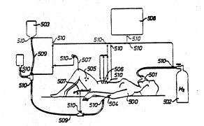
The measuring array shown in Fig. 7 shows a patient 500,
who is connected via a coded mask 501 to a hydrogen tank 502. An
infusion bottle 504 is connected by suita~le connecting elements `~
to an in~usion needle 504. Measuring sens~rs 506 and a surgical
instrument 507 are likewise connected to the measuring instrument
508 via connectina elements with corresponding connection ~ieces.
Implanted sensors 505 are provided with an electromagnetic,
readable code. All the utensils and instruments used are likewise
-14-
'
., . . ~ . . . . .
'' .; ' ; ' ~,:: ', ~', , :. " ,
provided ~ith a code ~10.
For long-te~m measurements, sensors with mul~iple
electrodes are preferably used, each of the elec~rodes for the
measurements being extended from a protective sheath or jacXet.
This jac~et may be of a resorbable material.
In the fur~her .eature, the sensors are provided with means
with which the electrodes can be bright sanded prior to each
measurement. It will be understood that this process and means
~or it may also be employed `in the technolosical and in industrial
fields.
In a proven embodiment, the sensors are connected to the
measuring instrument via five-oole electric leads-. In order not
to have to provide a separate electric lead for each of the coded
elements used, an I2 C-ous circuit, an RS 485, or an ~SB bus
system may be used, for instance, or the supply voltage for the -~
actlve coded elements or a cu~~ently commercially available TSS
400 signal processor may be clocked, in order to send the
measuring data over the same leads during the sleep mode of the
supply voltage. PALs (programmable logic arrays) are also
especially suitable for the encoding, because with them it is
again possible to make do with merely a two-wire lead. Explicit
reference is maàe here to the use of optical leads and
electrooptical components for the reading and measuring part of
the instrument. The most comfortable embodiment provides for an
integrated microprocessor in each case as coded elements. this
has recently made it possible to handle data transmission in the
form of a logical ring, hereina~ter described as "token ring H2".
The tokPn ring H2 is sent by active participants to
active participants in a numerically inc~easing order of -~
partl`cipant addresses, wi.h a token telegram. ~n e~ce2tion is the
par_icipant ha~ ng 'he highes_ address; ~ gi~/es a 'oken bac~ to ~-~
the central unit (which has the lowest address), to close the
~ ',
:; ''' ' '~
-15-
.~ , '
.
..... .
.' : , , . ' , :
:-' ' ' ., ., - . : . .
- . :. :. . .. . . ..
,:. ~ ~ : . . :: .
loglcal ring. ~hen one aclive par~icipant receives a token
tQlegram, addressed to it, from its predecessor, then it is
allowed to use the token and to handle message c~cles. Its
predecessor is determined on the basis of the entries in the list
of active stations (LAS), which was generated after power-on in
the list-token phase and later is updated continually upon receipt
of a token telegram. If the token sender is not the registered
predecessor, then the addressee must initially assume that an
error has occurred and ignores the token. Not until an ens~ing
repetitlon from the same predecessor dces acceptance occu-,
leading to token acceptance, since the receiver must assume that
the logical ring has changed. The receiver repla~es a list of
active stations (L~S) for the originally registe ed predecessors
with the new list. After po~er-on, the software of the active
participant changes to the list-token state, when it is ready for
the logical token ring. In this state, it must listen on the line
to ascertain which active participants are already in the logical
token ring. To do that, all the token telegrams received are
evaluated, and with the participant addresses contained in them
the list of active stations (L~S) is generated. .~fter t-~o
identical token cycles have been listened to in their entirety,
the so~tware s~i l remains in ~his s~ate until it is addressed by
its predecessor with a request status. It must acknowledge with
the status "rsadv for the ring" and then assume the active state.
If a request status is received during the LAS generation, then it
must acknowledge with the status "not ready for the ring". No ;-
other telegrams are processed in the list-token state; that is,
they are neither acknowledged nor answered. If, in detecting the
active participants, the soft~are recognizes its own address in
the source address or two token telegrams, then i~ ~ust assume
that a part-c~pant having the sa~e acdrQss is a'-eady locatQd in
the ring. It must then change to the of~-line state and send a
:
~:
-16-
... .. ," , ... , , ., ~, - . ,~ ., ~.; .... .
' , , ' ' 'I '' " ~' ' ' '
" '`' ' '
,, "' ~ ' ' "" '' "''' ' ''
repor~ to ~he manage~.nent (cen~~al unit).
If the soft~are perceives no bus activity over a relatively
long time, specificall~ during the time-out time, then it must
conclude from this that the token was lost and that the logical
ring must be rebuilt or restored, and it changes to the claim-
token state.
The soft~are assumes the claim-token state after the list-
token state or active state if its time-out period has elapsed, if
no bus ac~ivitv was ascer_ained dur ng a certain period of time,
and if it mus~ be assumed that the token was los.. In that state,
an attempt is made to reinitialize the logical ring or to start an
initialization. `~
The cent-al unit is accordingly capable at all times of
monitoring the nu~ber of active participants using the list of
active stations (LAS) and to trip an alarm immediately if there is
a change. With the management by means of a token ring as
desc-ibed above, the number of participants (hose, connecting
piece, sensor, etc.) is not limited to a certain number either,
and the various participants can be interconnected in an arbitrary
order. ~s a result, it Lollcws that for any conceivable
connection, only one processor type is used, always with the same
software, which naturall~ si~pliries the manufac_u~ing process
considerably. The ~arious components (hose, connecting piece, `~
sensor, etc.) are then me~ely additlonall~t loaded with some
component-specific data. These da-ta are stored in the EE~ROM
region of the processor and can accordingly be changed at any time
as needed. One possible requirement for change would be a change -~
of parameters because of empirical findings. These new parameters -~ ~
can then be loaced as a ne~ soft~are version (update) to the ~ :
central unit. If components that have not been loaded with the
~OSI recPnt data are ~hen incorpor~ed into the log~cal ring, ~he
central unit recognizes this from the version number, which once ~;
-17-
; . . , . ~
. . . ~ :,, ~ . .: :
.
,,: ~, ,, ~: . . : . :. , ,
~, .: , . .. . . . . .
:: : : :.: :
~':': ' . : : , :.
.. . . . .
again is stored in memory each time in the processor of the
various components, and can then chanqe the ent~ies in the
corresponding -~ROM via the token ring as needed. This assures
that even components that have not yet been loaded with the most
recent parameters can still be used.
The cent-al unit of the measuring instrument is thus
capable at any time of monitoring the active codes. In this
embodiment, t~e number o~ medical technology components used is
not subject to any soft-~are-dictated limitation, and they can be
connectad in an arbitrary, that is, non-specified, order and
combination without requiring that the software be adapted or
changed. Thus not only can basic data of the various medical
technology components be detec_ed, but e~piration dates, for
instance from preserved blood supplies, can also be stored in
memory and evaluated.
It will be understood that the above measuring and
monitoring process can also be done in a multiplexing mode or is
suitable for controlling medical manipulations, such as taking
periodic tissue samples, administering medication, etc.
-18-
.-:
,,
:: .. , . :
: , . .: :: : :