Note: Descriptions are shown in the official language in which they were submitted.
` ~ WO92/10334 PCT/AU91/0049~
f 2096959
MACHINE FOR USE IN THE MANUFACTURE OF POWER STEERING VALVES
This invention relates to apparatus for manufacturing
fluid control contours in components of rotary valves such
as used in hydraulic power steering gears for vehicles.
Such rotary valves include an input-shaft which
incorporates in its outer periphery a plurality of
blind-ended, axially extending grooves separated by lands.
Journalled on the input-shaft is a sleeve having in its
bore an array of axially extending blind-ended slots
matching the grooves in the input-shaft, but in underlap
relationship thereto, the slots of the one being wider than
the lands of the other so defining a set of axially
extending orifices which open and close when relative
rotation occurs between the input-shaft and the sleeve from
the centred or neutral condition, the magnitude of such
rotation henceforth referred to as the valve operating
angle. The edges of the input-shaft grooves are contoured
so as to provide a specific orifice configuration often
referred to as metering. These orifices are ported as a
network such that they form sets of hydraulic Wheatstone
bridges which act in parallel to communicate oil between
the yrooves in the input-shaft and the slots in the sleeve,
and hence between an engine driven oil pump, and right-hand
and left-hand hydraulic assist cylinder chambers
incorporated in the steering gear, thereby determining the
valve pressure characteristic.
The general method of operation of such rotary valves
is well known in the art of power steering design and so
will not be described in any greater detail in this
specification. A description of this operation is
contained in US Patent 3,022,772 (Zeigler), commonly held
as being the "original" patent disclosing the rotary valve
concept.
Such rotary valves are nowadays regularly incorporated
in firewall-mounted rack and pinion steering gears
WO9~/10334 PCT/AU91/0049~ ~
_ _ - 2 - 209~9~9
. .,
and, in this situation, any noises such as hiss emanating
from the valve are very apparent to the driver. Hiss
results from cavitation of the hydraulic oil as it flows
in the orifices defined by the input-shaft metering
edge contours and the adjacent edges of the sleeve slots,
particularly during times of high pressure operation of
the valve such as during vehicle parking manoeuvres. It
is well known in the art of power steering valves ~hat an
orifice is less prone to cavitation if the metering edge
contour has a high aspect ratio of width to depth, thereby
constraining the oil to flow as a thin sheet of constant
depth all along any one metering edge contour. Similarly
it is important that the flow of oil divides equally
amongst the aforementioned network of orifices, so further
effectively increasing the above aspect ratio. This
requires highly accurate angular spacing of the
input-shaft metering edge contours as well as the
precision of manufacture of each metering edge contour to
ensure uniformity of depth along their length. Precision
is most important in that portion of the metering edge
contour controlling high pressure operation of the rotary
valve associated with parking manoeuvres, where the
pressure generated is typically 8 MPa and the metering
edge contour depth only about 0.012 mm. This portion lies
immediately adjacent to the outside diameter of the
input-shaft, and is associated with the maximum normal
operating angle of the valve. However precision is also
required in order to avoid hiss further down the metering
edge contour where the pressure generated is typically 2
MPa and the contour depth about 0.024 mm. The remainder
of the metering edge contour towards the centred position
of the rotary valve is important in determining the valve
pressure characteristic, but not valve noise.
It is also well known that cavitation is less likely
to occur if the metering edge contour is of a wedge
~ WO92/10331 PCT/AU91/0049~
209~9~9
configuration having a slope of no more than about l i~ 12
with respect to the outside diameter of the input-shaft.
The low slope of the metering edge contour in the parking
region makes it difficult to achieve the abovementioned
highly accurate angular spacing of the metering edge
contours, the latter spacing which controls valve
operating angle and hence, not only valve noise, but also
the steering gear parking efforts.
Several manufacturers seek to achieve the above
described accuracy by grinding metering edge contours in
special purpose chamfer grinding machines in which the
input-shaft is supported on centres previously used for
cylindrically finish grinding its outside diameter. Such
machines have a large diameter grinding wheel, of a width
equal to the axial extent of the metering edge contours,
which s successively traversed across the edge of each
input-shaft groove thereby producing a series of flat
chamfers. In some cases each metering edge contour is
constructed from a number of flat chamfers, usually one,
two or even three flat chamfers per metering edge contour
requiring, for example, as many as 36 separate traverses
of the grinding wheel to manufacture the metering edge
contours of a six slot input-shaft. Such a manufacturing
method is therefore time consuming and expensive.
Other manufacturers adapt, for this purpose, grinding
machines termed cam grinders, similar to those used for
example in the manufacture of camshafts for automobile
engines, thread cutting taps, and router cutters, wherein
the workpiece is supported on centres and rotated
3Q continuously while being cyclically moved towards and away
from a grinding wheel under the action of a master cam.
The required amount of stock is progressively removed by
infeeding of the grinding wheel during many revolutions of
the workpiece. As in the case of chamfer grinding
machines, a large diameter grinding wheel is used, which
WO92/1033~ PCT/AU91/0049~ -
20969~9
makes it impossible to grind that part of the metering
edge contour towards the centreline of the groove where
increasing depth would cause the grinding wheel tO
interfere with the opposite edge of the same groove. This
steeply sloping and relatively deep portion of the
input-shaft metering edge contour will henceforth be
referred to as the "inner" metering edge contour and its
geometry generally affects the on-centre region of the
valve pressure characteristic. This portion is generally
manufactured by means other than the chamfer or cam
grinding machines just described which, for reasons
stated, are only capable of grinding the "outer" metering
edge contour. This previously described gently sloping
wedge shaped portion of the metering edge contour
determines the valve pressure characteristic at medium and
high operating pressures, as well as determining the Jalve
noise characteristic.
In the case of both chamfer and cam grinding methods
described, the outside diameter of the hardened
input-shaft is usually cylindrically ground on centres in
an operation immediately prior to grinding the outer
metering edge contours on these same centres. This is
required because these centres are necessarily turned in
the ends of the input-shaft workpiece prior to hardening
and hence are no longer concentric with respect to its
outside diameter after hardening, due to metallurgical
distortion. However, for the same reasons, this method of
processing inevitably results in the array of input-shaft
grooves, machined on the same centres by milling or
hobbing methods prior to hardening, being eccentric with
respect to the input-shaft outside diameter.
Present manufacturers who chamfer grind metering edge
contours by the methodology just described frequently true
the sides of the axially extending input-shaft grooves
using a small diameter, high speed grinding wheel, which
092/10334 PCT/AU91/0049
- 5
2û969S9
is plunged radially into each groove. Such a truing
operation, however, is not feasible in the case of cam
grinding machines. Another method sometimes used to true
the resulting eccentricity of the grooves after hardening
is to re-true the centres in the input-shaft workpiece
immediately after hardening by colleting the input-shaft
in a fixture which locates on the outside diameter of the
input-shaft adjacent to the grooves. Such re-trued
centres can then be reliably used for subsequent
cylindrical grinding of the outside diameter of the
input-shaft as well as for grinding the metering edge
contours. Whichever method is used for correcting the
eccentricity of the array of input-shaft grooves, however,
results in significant increases in time and therefore
cost in the processing.
However the major disadvantage of processing both the
input-shaft outside diameter and metering edge contours on
centres is that the former of these two steps, that is
cylindrically grinding the outside diameter of the
input-shaft on centres, is much less efficient than the
more commonly used centreless cylindrical grinding
process. Centreless cylindrical grinding is generally
more highly accurate than cylindrical grinding on centres,
and can be readily implemented as a "through feed" or
continuous process, leading to much reduced overall cycle
times. Moreover, the expected accuracy gains of
processing both the input-shaft outside diameter and the
metering edge contours on centres may not always
eventuate, and the array of metering edge contours may
still be eccentric with respect to the input-shaft outside
diameter. This residual eccentricity can be caused by
damage to the fragile female centres of the input-snaft
workpiece which are typically non-hardened.
It is apparent that many of the disadvantages of
processing the hardened input-shaft on centres could be
=
WO92/10334 PCT/A~191/0049~ -
2096959
overcome by carrying out all such post-hardening
operations in a centreless manner: that is centreless
cylindrically grinding of the input-shaft outside diameter
followed by centreless grinding of the metering edge
contours. In the latter process the so-called control
wheel would be moved in and out during grinding in a
manner co-ordinated with the rotation of the input-shaft,
so progressively grinding all contours around the outside
periphery of the input-shaft. However, as referred to
earlier, it is a necessary requirement that the valve
operating angle be closely controlled, and the angular
disposition of the points of intersection of the metering
edge contour and the input-shaft outside diameter also
accurately maintained. By using such a centreless
grinding method for the input-shaft metering edge
contours, the depth of any contour being ground would be
determined by the distance between such contour and the
diametrically opposite portion of the input-shaft outside
diameter (corresponding to the point of contact with the
control wheel). The depths of the metering edge contours
so ground would vary not only in accordance with any
errors in the contour grinding operation but also, in
addition, absolute diametral errors resulting from the
prior centreless grinding cylindrical operation carried
2~ out on the input-shaft outside diameter.
As far as is known such centreless grinding of
metering edge contours has never been carried out
commercially, perhaps due to this limitation associated
with compounding of the errors.
The present invention involves a method of supporting
of the input-shaft during centreless grinding of the
metering edge contours and enables the metering edge
contours to be accurately disposed with respect to the
immediate outside diameter of the input-shaft, as compared
3~ to the diametrically opposite portion of the outside
~ 092/1033~ : PCT/AU91/0049~
~ 7 ~ 20969~9
e
diameter. Absolute depths and angular dispositions of the
metering edge contours can therefore be maintained without
the compounding of errors earlier referred to. It is
therefore possible to take full advantage of the benefits
of centreless processing of the input-shaft.
The present invention consists in a machine for
grinding the metering edge contours on edges of axially
extending grooves of a power steering valve input-shaft
having support means for supporting said input-shaft for
rotation, a substantially cylindrical grinding wheel whose
working surface is dressed parallel to the axis of said
input-shaft, drive means to rotate said input-shaft, means
to increase and decrease cyclically the distance between
said axis of said input-shaft and said grinding wheel
several times during each revolution of said input-shaft
to grind said metering edge contours, each said metering
edge contour so ground having a contour which is a mirror
image of the contour of at least one other metering edge
contour around the periphery of said input-shaft,
producing symmetrical sets of clockwise and anticlockwise
metering edge contours characterised in that said support
means comprises support surfaces tangentially contacting
the outside diameter of said input-shaft, a first two of
said support surfaces being axially displaced on either
side of the ends of said grooves, and being arranged one
on each side of said grinding wheel on that side of the
input-shaft adjacent said grinding wheel and another said
support surface or other said support surfaces being
arranged substantially at right angles to said first two
support surfaces to constrain the input-shaft against
motion in a direction parallel to said first two support
surfaces, a pair of pressing members contacting said
outside diameter of the input-shaft, one each displaced
axially either side of the ends of said grooves and loaded
3~ so as to press said input-shaft in a direction generally
WO92/1033~ PCT/AU91/0049~ -
- 8 - 2096959
towards said first two support surfaces, thereby
centrelessly supporting the input-shaft during grinding of
the metering edge contours.
A further advantage of using the machine just
described relates to the widely used practice of selective
assembly during manufacture of power steering valves.
Because of the need to very closely control the diametral
fit between the input-shaft and its surrounding sleeve
member (typically between 0.007 and 0.012 mm on diameter),
it is common practice to manufacture both sleeve and
input-shaft over a somewhat larger diametral range of
about 0.025 mm and subsequently selectively match the
pairs during the valve assembly operation. By using the
centreless grinding machine having supports as taught in
lS the invention, a precise disposition of the metering edge
contours is achieved, irrespective of the absolute
diameter of the particular input-shaft being ground. This
is not possible with prior art methods described earlier
wherein the grinding operation would require to be
continually adjusted in depth in order to ensure a precise
angular disposition of the metering edge contours. Also,
eccentricity errors between the outside diameter of the
input-shaft and the metering edge contours are eliminated.
The present invention will now be described by way of
example with reference to the accompanying drawings in
which:-
Figure 1 is a three dimensional perspective view ofthe overall grinding machine;Figure 2 is a magnified sectional view on plane DD in
Figure 1 normal to the input-shaft axis showing the method
of support of the input-shaft in the grinding machinei
Figure 3 is a sectional view on plane DD in Figure 1
of the grinding machine;
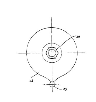
Figure 4 is a view of a cam shown in Figure 1 normal
to its axis;
~ 092/1033~ PCT/AU91/0049~
9 2096959
Figure 5 is an enlarged view of the metering edge
contour ground on the edge of one input-shaft groove.
Figure 1 shows schematically the principal features
of the grinding machine in which grinding wheel l is
mounted on a spindle having an axis 2 housed in journal 3
carried on slide 4 operable in slideway 5 which forms part
of machine base 6.
Now referring to Figures 2 and 3, input-shaft 7 is
supported for rotation on two pairs of wear resistant
support pads, the first pair 8 and 8a, one on each side cf
the grinding wheel and axially displaced beyond the ends
of the grooves, and the second pair g and 9a (obscured in
Figure 1) underneath input-shaft 7, serving to support it
in a direction parallel to the faces of the first pair 8
and 8a. Rollers 10 and 11 are journalled on pin 12 in
yoke 13 which itself is pivoted on pin 14 in forked
support bloc~ 15 which also provides a mounting for
support pads 8, 8a, 9 and 9a. Spring 16 serves to
maintain pressure between rollers 10 and 11 and the
outside diameter of input-shaft 7, yet allows yoke 13 to
be pulled back in order to remove input-shaft 7 on
completion of the grinding operation. Forked support
block 15 is secured to rocking platform 52 which is
journalled for oscillation about pivots 17 and 18, that is
about axis 19. Pivots 17 and 18 are carried by pedestals
20 and 21 respectively, which form part of machine base 6.
Input-shaft 7 has two flats 22 machined thereon which
are gripped by the two jaws of chuck 23 which are hinqed
on the front of disc 24 of an Oldham coupling, the rear
member which comprises flange 25 of main work spindle 26.
The manner of opening and closing the jaws of chuck 23 is
conventional. Main work spindle 26 is journalled on
pedestal 27 which forms part of rocking platform 52 and is
rotated by worm wheel 28 secured thereon. Worm 29
integral with worm shaft 30, engages worm wheel 28 in a
WO92/10334 PCT/AU91/0049~ ~
- lO - 2096959
slack free manner and is journalled for rotation but
restrained from axial sliding in journal plates 31 and 32
extending vertically from rocking platform 52. Worm shaft
30 extends forwardly of journal plate 31 (in Figure 1) and
has pinion teeth 33 cut thereon, and extends rearwardly of
journal plate 32 ~ support gear 34 which engages pinion
35 of motor 36. Motor 36 is mounted on bracket 37 which
forms an integral part of rocking platform 52 and
therefore oscillates therewith about pivots 17 and 18.
Gear 38 is carried on shaft 39 and meshes with pinion
teeth 33 of worm shaft 30. Shaft 39 is also journalled
for rotation in journal plates 31 and 32, but restrained
from axial sliding therein.
The ratios of pinion teeth 33, gear 38, worm 29 and
worm wheel 28 are such that when grinding a six groove
input-shaft, shaft 39 makes six revolutions for one
revolution of main work spindle 26.
Cam 42 contacts follower pin 40 journalled in slider
41 within boss 43 extending from rocking platform 52. At
its lower end slider 41 rests on pin 44 secured to machine
base 6. Spring 45, also secured to machine base 6 by
headed pin 53, keeps cam 42 in contact with follower pin
40 and slider 41 in contact with pin 44, and assures a
positive, slack-free oscillation of rocking platform 52 in
accordance with the lobed profile of cam 42 (see detail in
Figure 4).
Upon starting motor 36, main work spindle 26 and
input-shaft 7 commence to rotate in the direction shown
and slide 4 immediately feeds in a small amount in order
to commence grinding input-shaft 7. The width of grinding
wheel 1 is such as to grind the entire width of the
metering edge contour.
Figure 5 shows, at a greatly enlarged scale, the
position earlier shown in Figure 2 in which one of the
previously machined axially extending grooves 46 is
WO 92tlO334 PCT/AU9l/0049~
- 11 - 20969~9
aligned with the axis 2 of grinding wheel 1. The profile
of cam 42 is such that grinding wheel 1 has produced a
substantially flat metering edge contour between points 47
and 48 and a scroll-like metering edge contour between
points 48 and 49. Point 50 corresponds to the point on
the metering edge contour with a depth of 0.012mm,
normally associated with the generation of maximum parking
pressures in the valve.
Cam 42 revolves six times to complete all 12 metering
edge contours of a six groove input-shaft (as illustrated)
or eight times to complete all 16 metering edge contours
of an eight groove input-shaft (not shown).
It will be appreciated by persons skilled in the art
that numerous variations and/or modifications may be made
li to the invention as shown in the specific embodiments
without departing from the spirit or scope o~ the
invention as broadly described. The present embodiments
are, therefore, to be considered in all respects as
illustrative and not restrictive.
-