Note: Descriptions are shown in the official language in which they were submitted.
2ûg~9J~ '
- 1 -
Metallic Transmi~ion Medium Di~po~ed
In Stabilized Plastic Insulation
Technical Field
This invention relates to a metallic transmission medium
5 disposed in a stabilized plastic insulation.
Back~cround of the ~n~ention
As is well known, metallic conductor transmission media have
been used widely in communications. Such media typically include a
plurality of twisted pairs of insulated conductors which comprise a core
10 Each insulated conductor typically includes a metallic conductor having a
layer of an insulation material thereabout. The core typically is enclosed in
a sheath system which includes at least a plastic jacket.
Although over the last decade, optical fiber transmission has
enjoyed a spectacular climb in use, metallic conductors continue to be used.
15 However, in such a competitive environment, it behooves any manufacturer
of cables which include insulated metallic conductors, to overcome any
problems which have manifested themselves.
One such problem relates to an insulation system which is used
to enclose each metallic conductor. Typically, that insulation system
20 comprises an inner layer of a cellular or expanded insulation whereas an
outer layer comprises a solid insulation material. In many instances, the
insulation material is a composition which comprises a polyolefln plastic
material, and, more particularly, a polyethylene plastic material and a
stabilization system.
Such insulation material has been found to possess excellent
mechanical and electrical properties. However, it also has been determined
that the relatively low thermal stability of polyolefins may lead to a problem
after long term use. Unless this problem is addressed, the insulation
material may crack where exposed to relatively high temperatures. Such
30 temperatures may occur, for example, in areas of the southwestern portions
of the United States. The cracking of conductor insulation occurs when
portions of insulated conductors of aerial or buried cables become exposed
to air in splicing environments such as in closures, for example.
- 2- 209699~
There is some thought that the lack of thermal stability may be
caused by the extraction of constituents of a stabilization system of the
insulation composition by ~llling materials which are used widely in
communications cables. Further, it has been shown that an adverse
5 reaction occurs between the surface of a copper conductor and the
stabilization system of the insulation material. As a result, the copper of
the metallic conductor catalyzes the oxidation of the polyethylene insulation
which then deteriorates at an accelerated rate. Copper catalyzed oxidat;on
of polyolefin insulation leads to the premature failure of communications
10 cables.
The stabilization of cellular insulation over copper conductors
has been discussed in an article authored by M. G. Chan, V. J. Kuck~ F. C.
Schilling, K. D. Dye and L. D. Loan entitled "Stabilization of Foamed
Polyethylene Communication Cable Over Copper Conductors" which
15 appeared in the proceedings of the Thirteenth Annual International
Conference on Advances In The Stabilization and Degradation of Polymers
held in Luzern, Switzerland on May 22-24, 1~
Manufacturers have addressed the problem of stabilization, and,
as a solution, have included in the composition of the insulation material an
20 antioxidant and a metal deactivator. See, U.S. patent 3,668,2~8. Further,
more recently, the levels of antioxidant and of metal deactivator
constituents in the insulation composition have been increased. However, it
was believed that there were certain outer limits of the amount of stabilizer
that should be used. For example, it was believed that the addition of
25 stabilizer including antioxidant and metal deactivator functions at a level of
about 0.25% by weight would satisfy all the requirements for long term use.
What is sought after and what appears not to be available in the
prior art is a cable which includes a conductor insulated with a polyolefin
composition which has suff~lcient thermal stability to cause the integrity of
30 metallic conductor insulation to be maintained over a relatively long period
of time as predicted by currently used tests. The sought-after composition
desirably should be reasonable in cost and easily applied to a metallic
conductor without the need of additional capital investment.
~, 209699~
- 3-
S-lmm~ry of the Invention
The foregoing problems of the prior art have been overcome by a
cable which includes a transmission medium disposed in an insulation
system.
Brief Description of the Drawin~
FIG. 1 is an end sectional view of a cable which includes a core
compr;sing a plurality of plastic insulated conductors and a sheath system;
FIG. 2 is an end view of an insulated conductor having two
stabilized concentric layers of insulation, an inner one of the layers being an
10 expanded plastic material and referred to as a foam layer and an outer one
of the layers being referred to as a skin;
FIG. 3 is a graph which depicts levels of a bifunctional stabilizer
in insulation after processing and preaging as a function of the average
weight percent of the bifunctional stabilizer in the skin and in the foam in
15 the raw material stage;
FIG. 4 is a graph which depicts oxidation induction time as a
function of the average weight percent of a bifunctional stabilizer in raw
materials for the foam and the skin layers; and
FIG. 5 is a graph which depicts the results of a pedestal test.
20 Detailed De~cription
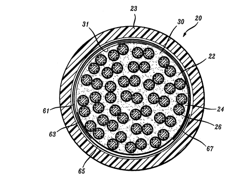
Referring now to FIG. 1, there is shown a communications cable
which is designated generally by the numeral 20. The cable 20 includes a
core 22 and a sheath system which includes a jacket 23.
The core 22 includes a plurality of pairs 24-24 of plastic insulated
25 metallic conductors 26-26. Each of the insulated conductors 26-26 (see FIG.
2) includes a metallic conductor 25, which typically is copper, and an
insulation system 27.
The insulation system 27 comprises two layers, an inner layer 28
compr;sing an expanded plastic material, also termed a cellular plastic
30 material. The layer 28 is often referred to as the foam layer. The plastic
material of the inner layer is a composition of matter comprising a
polyolefin plastic material, a blowing agent, and a stabilization system.
Typically, the polyolefin plastic material is polyethylene.
~_ 4 ~i~96gg5
The inner layer comprises a polyolef~ln such as polyethylene
which has been expanded by a chemical blowing agent. Although others
may be used, a preferred blowing agent is azodicarbonamide. The chemical
ætructure of same is as follows:
H2 N -- CO -- N = N -- CO -- NH2.
During the insulating process, the blowing agent is decomposed to provide
gas. The final insulation layer 28 includes decomposition products of the
blowing agent.
The insulation system 27 also includes an outer layer 2~. The
10 outer layer 2~ which often is referred to as the skin layer comprises a solidplastic material such as polyethylene, a stabilization system and a colorant
material. For 2B AWG copper wire, the diameter of the metallic conductor
is 0.016 inch and the outer diameter of the insulated conductor is about
0.029 inch. The outer skin layer has a thickness of about 0.002 inch. The
15 quantity of plastic material per unit length of the inner layer is substantially
equal to that of the outer layer. Preferably, the plastic material of the inner
layer and of the skin is a polyolefin such as high density polyethylene or
polypropylene, for example. The foregoing insulated conductor often has
been referred to as DEPIC which is an acronym for dual expanded
20 polyethylene insulated conductor.
Disposed within the core is a filling material 30. One such filling
material is a Flexgel filling material. Flexgel is a registered trademark of
AT&T. A suitable filling material is disclosed in U.S. patent 4,464,013.
Another filling material is disclosed in U.S. patent 4,870,117. Still another
25 filling material is one comprising polyethylene and petrolatum, typically
referred to as PE/PJ. See U.S. 3,717,716. The filling material, which also is
stabilized, becomes disposed in interstices among the conductors and
between the conductors and a tubular member 31, which typically is
referred to as the core wrap.
Each layer of conductor insulation is provided with a stabilizer
system which includes an antioxidant function and a metal deactivator
function and includes a portion which has a relatively high resistance to
extraction by filling materials. By antioxidant is meant a chain terminator
and/or a peroxide decomposer. By a metal deactivator is meant that which
35 chelates metal ions. In the prior art, stabilization systems for polyolefins in
metallic conductor insulation have included a combination of an antioxidant
~ 5~ 2036~95
such as, for example, a sterically hindered phenol and a metal deactivator.
In the preferred embodiment, each layer of insulation includes
Ciba Geigy Irganox~l9 1010 and Irganox MD 1024 stabilizers, the latter being
bifunctional and functioning both as a metal deactivator and an
5 antioxidant. The chemical name as used in the Code of Federal Regulations
for Irganox 1010 is tetrakis [methylene (3,~di-tert-butyl-4-hydroxy-
hydrocinn~n~e)l methane. The CAS name for the latter is
2,2--bisll3--~3,5--bis(1,1 dimethylethyl)
--4--hydroxy pheny1`l--1--oxopropoxyl methyl~--1,3--propanoate
10 propanediyl 3,5--bis(1,1--dimethylethyl)--4--hydroxybenzene. On the
other hand, the chemical name for Irganox MD 1024 is N'N'--bis
[3--(3',5'di--tert--butyl--4--hydroxy--phenyl) propanyl--hydrazine.
The CAS name for 1024 is 3,5--bis(1,1--Dimethylethyl)--4--
hydroxy--benzenepropanoic acid2--[3--13,5--bis--(1,ldimethylethyl)--4--
15 hydroxy--phenyl--1--oxopropyl] hydrazide.
The Irganox 1010 stabilizer is relatively extractable. On the
other hand, the bifunctional Irganox 1024 stabilizer has a relatively high
resistance to extraction. Typically, each of the inner and outer layers of
insulation includes 0.15% by weight of the Irganox 1010 stabilizer. The
20 weight percent of the bifunctional stabilizer is discussed hereinafter.
Oxidative cracking can occur in either insulation layer and must
be retarded. The oxidation of the insulation can be catalyzed by the copper
conductor which is contiguous to the cellular layer. A stabilizer system
which may include antioxidanttmetal deactivator functions is included in
25 the insulation material to prevent the copper from breaking down the
insulation. However, when the insulation is exposed to some filling
materials, the amount of stabilizer in the insulation is reduced by extraction
or by reaction. Also, in addition, the interaction of the reaction products of
the blowing agent with the stabilization system may reduce the effectiveness
30 of the stabilization system. Because of its relatively small size, a 26 gauge DEPIC is the most rulnerable to these problems.
Tests were conducted at various concentrations levels of the
stabilizer system. As seen in FIG. 3 a curve 32 depicts a calculated average
weight percent of bifunctional stabilizer present in the raw material, skin
35 and foam, in a 50:50 ratio. A curve 33 depicts the actual average
bifunctional stabilizer after the raw material has been applied to the copper
- 6- 2096995
conductor as measured by high performance liquid chromatography (HPLC).
Then the insulated conductor is preaged for four weeks in the presence of a
filling material. For a four-week preage, it can be seen that the residual
amount of bifunctional stabilizer is independent of the original amount of
5 bifunctional stabilizer in the skin layer and dependent on that in the foam
layer. As the level in the foam layer increases, the residual amount
increases.
One measure of the degree of stability in a polyolefin plastic
material is a parameter Icnown as the oxidative induction time ~OIT), at an
10 elevated test temperature. ASTM procedures specify the elevated test
temperature as 199 C whereas the Rural Electrical Association (REA)
specifies 1~ C for solid polyolefins and 1~0 C for expanded polyole~lns.
See ASTM D 4565. OIT is an indication as to how well stabilized is a
material by measuring how long the material will resist oxidation at a test
15 temperature without degrading in the presence of pure oxygen. The higher
the OIT, the better the stability.
Before the OIT test is performed, it is commonplace in the
industry to preage the test cable for two weeks at 70 C to facilitate
permeation of the insulation with the filling material. Such preaging is
20 believed to simulate the experience of the cable in a reel yard of a
manufacturer as it awaits shipment and installation.
Going now to FIG. 4, there is shown a curve 35 which plots OIT
in minutes at 200 C versus the average amount of Irganox ~) 1024
bifunctional stabilizer in the raw materials for the insulation system
25 comprising a cellular inner layer and a solid outer layer. The average level
of the bifunctional stabilizer ranges from about 0.4 to 0.8 percent by weight.
As is seen, the OIT increases as the average stabilizer level increases.
In FIG. 4 also is depicted a curve 37 which shows the OIT for an
insulation which has been preaged for two weeks in a cable structure which
30 included a filling material, more particularly a Flexgel filling material. The
curve designated 37 represents an insulation system in which the
bifunctional stabilizer level in the cellular inner layer is about 0.8% by
weight whereas the bifunctional stabilizer level for the skin varies. A
system shown by the numeral 41 represents a solid or skin layer having a
35 stabilization level of about 0.4% by weight. Numerals 43 and 45 represent
insulation systems having values of about 0.6 and 0.8 bifunctional stabilizer
2096995
- 7 -
levels in the skin.
It has been known that a decrease in OIT will result from a
decrease in stabilization level. However, what has not been known and
what is shown in FIG. 4 is that the level of stability of the insulation system
5 after exposure to cable filling material is determined by the weight percent
of the stabilizer in the cellular layer and is independent of the level of
stabilizer in the skin.
Allother test which is used to test oxidative stability is the so-
called pedestal test. See Bellcore Technical Reference TR-NWT-00421 Issue
10 3, September 1~91. Whereas the hereinbefore described OIT test is a quick
test, the pedestal test is a long term test. It is precisely referred to as the
Pedestal Thermal Oxidative Stability Performance Test. The Pedestal
Thermal Oxidative Stability Performance Test is an accelerated test
intended to simulate exposure of the insulated conductors to field
15 conditions.
The cable to be tested is conditioned at an elevated temperature
prior to the thermal oxidative stability test. Individual conductors are then
removed from the preconditioned cable, wiped and stressed by wrapping
them around a mandrel whose diameter equals the outer diameter of the
20 insulated conductor. The stressed conductors are exposed at an elevated
temperature in telephone pedestals for a specific time period (e.g., ~0 C,
260 days). At the end of this period, the insulation on the conductors is
examined for cracking.
For the test, a standard 6 inch (152 mm) square metal pedestal
25 48 inches (1.2 m) long is preferred. All internal terminal plates,
polyethylene liners, frames, grounding wire, etc., which are not necessary to
support wire samples may be removed. Metal brackets may be installed for
mounting wire samples and monitoring probes. A heat source tightly
surrounds the upper 12 inches of the pedestal.
The base of the pedestal may be plugged with cotton or
cheesecloth to reduce the temperature gradient inside the pedestal. The use
of R11 fiberglass/rockwool house insulation around the test pedestal
beneath a heating mantle is found to reduce significantly the temperature
gradient inside the pedestal. A temperature control system capable of
35 maintaining the temperature of all the insulated conductor coils inside the
pedestal within :~2 C of the specifled test temperature is used. In the case
-8- 2~9699S
of a ~0 C test, the temperature range (absolute) will be 88 C to ~2 C. A
separate system capable of monitoring and permanently recording internal
temperature at intervals not to exceed four hours is used.
For testing, a finished cable, 25 pair or larger, that includes the
5 smallest size conductors available is used. A 30 inch (762 mm) length of
cable is cut from the length of cable and each end sealed with vinyl tape or
capped. The sealed cable is placed in an oven at 70 C (158 F) for 28 days.
At the end of the condit;oning period, the samples are cooled to room
temperature and 50 insulated conductors (5 samples of each color) are
10 selected. If filled cable ;s used, each conductor is wiped with a clean cotton
cloth or paper towel. No solvent is used to remove the filler. Each
conductor is wrapped in 10 close turns around the mandrel starting 13
inches from one end of each of the 50 conductors. To minimize the
variation of stresses developed during winding, the angle of the wire with
15 the mandrel is maintained greater than 70 degrees. The mandrel is moved
slidably out of the coiled area without disturbing the circular configuration
of the wrapped conductor.
Each coiled conductor sample is attached to the metal bracket so
as to form an inverted U-shaped loop whose coil apex is at the same level as
20 the monitoring temperature sensor located 3 to 6 inches ~76 to 152 mm)
from the top inside surface of the pedestal. The monitoring temperature
sensor is placed in the middle of the conductor coils at the top of the
inverted loop and secured to the pedestal or bracket. It is important that
the sensor be on the same horizontal level as the topmost coil and that all
25 coils vary not more than +2 C of the specified temperature.
A probe mounted vertically with its tip upwards and located at
the same height as the lowest coil is required to verify periodically or
continuously that the temperature of the lowest coil remains within +2 C
of the specified temperature. The control probe is mounted to the wall of
30 the pedestal at the same height as the monitoring temperature sensor, or at
the center axis of the pedestal at the same height. A high temperature
cutoff system is used to prevent the sample loss and the nonconformity
caused by an over temperature condition. It is recommended that the
temperature cutoff probe be positioned adjacent to the temperature
35 monitoring sensor at the topmost coil.
2~96995 -
~ lth all coils and sensors in place, the front cover of a pedestal
is secured and the heating mantle is placed over the pedestal. Samples are
tested at ~0 C (1~4 F) temperature for 260 days.
The test is completed after heating for the specifled duration of
5 test. The duration is adjusted for any period the samples are not at the
specified temperature, such as during observation time or power failure. All
insulated conductor coils are maintained at ~0 ~ 2C (1~4 ~t4F) during
the aging for 260 days. For an insulation system to pass, not more than one
insulation sample shall show any v;sible cracking when examined under 5X
10 magnification after completion of the above test temperature. Testing also
is carried out at 110 C to accelerate testing and to obtain results more
quickly.
Going now to FIG. 5, there is shown a plot of days to first crack
at 110 C versus the average amount of 1024 stabilizer (in weight percent) in
15 the raw material stage in the skin and in the foam layers. As can be seen,
data points 52-52 and 54-54 represent a conductor having about 0.4% and
0.6%, respectively, of bifunctional stabilizer in the foam. As the weight
percent of the bifunctional stabilizer in the foam increases, the number of
days to first crack increases. For a conductor having about 0.8% of
20 stabilizer in the foam as represented by data points 56-56, about 210 to 245
days expired before first cracks were noticed. These data show that the
weight percent of bifunctional stabilizer in the foam layer determines the
performance of the composite foam/skin insulation in the pedestal test and,
as evidenced by the horizontal lines in FIG. 5, the performance is
25 independent of the weight percent of stabilizer in the skin.
From these results, it may be concluded that the stabilization
level in the cellular layer is determinative. In order to prevent cracking of
the insulation, a level of bifunctional stabilizer at least about 0.4% by
weight and preferably in the range of 0.4 to 0.8% by weight which is
30 enhanced over that used on the prior art is needed in the inner, cellular
layer.
This result flies in the face of normal accepted practice in the
industry in which the amount of stabilizer in the inner layer has been
relatively low and about the same as in the skin layer. Over the years, the
35 level of the bifunctional stabilizer in the cellular layer and in the skin layer
gradually increased from about 0.1% to about 0.2% by weight. What has
2096995
been found is that the stability of the insulation is independent of the
amount of the weight percent stabilizer in the skin.
Returning now to FIG. 1, the description of the cable of which a
plurality of the insulated conductors forms a core will now be completed.
5 Disposed about the tubular member 31 is a shielding system which includes
an aluminum inner shield 61. The aluminum inner shield is wrapped about
the tubular member 31 to form a longitudinal overlapped seam 63. About
the inner shield 61 is disposed a steel outer shield 65 which has a
longitudinally extend;ng overlapped seam 67. Typically, the overlapped
10 seams 63 and 67 are offset circumferentially. The plastic jacket 23 is in
engagement with an outer surface of the steel outer shield 65. Of course, in
order to provide access to the insulated conductors to carry out splicing
operations, for example, the sheath system is removed from an end portion
of the cable in a closure or in a pedestal.