Language selection

Search

Patent 2097313 Summary

Third-party information liability

Some of the information on this Web page has been provided by external sources. The Government of Canada is not responsible for the accuracy, reliability or currency of the information supplied by external sources. Users wishing to rely upon this information should consult directly with the source of the information. Content provided by external sources is not subject to official languages, privacy and accessibility requirements.

Claims and Abstract availability

Any discrepancies in the text and image of the Claims and Abstract are due to differing posting times. Text of the Claims and Abstract are posted:

  • At the time the application is open to public inspection;
  • At the time of issue of the patent (grant).
(12) Patent: (11) CA 2097313
(54) English Title: A ROTARY SCREEN DEVICE
(54) French Title: CRIBLE ROTATIF
Status: Deemed expired
Bibliographic Data
(51) International Patent Classification (IPC):
  • B07B 1/08 (2006.01)
  • B01D 33/15 (2006.01)
  • B07B 13/16 (2006.01)
(72) Inventors :
  • JONES, THOMAS RICHARD (United Kingdom)
  • PHILLIPS, REGINALD LEYLAND (United Kingdom)
  • FALCON-STEWARD, HUGH ROBIN (United Kingdom)
(73) Owners :
  • ECC INTERNATIONAL LIMITED (United Kingdom)
(71) Applicants :
  • ECC INTERNATIONAL LIMITED (United Kingdom)
(74) Agent: ROBIC
(74) Associate agent:
(45) Issued: 1998-08-04
(86) PCT Filing Date: 1991-11-28
(87) Open to Public Inspection: 1992-05-30
Examination requested: 1994-07-08
Availability of licence: N/A
(25) Language of filing: English

Patent Cooperation Treaty (PCT): Yes
(86) PCT Filing Number: PCT/GB1991/002107
(87) International Publication Number: WO1992/009375
(85) National Entry: 1993-05-28

(30) Application Priority Data:
Application No. Country/Territory Date
9026030.8 United Kingdom 1990-11-29

Abstracts

English Abstract


In a rotary screening device the screen or sieve (12) is stretched across the upper end of the drum (1A) which is rotated
about the vertical axis, and the walls of the drum (1A) are frusto-conical or of parabolic section, diverging outwardly to its lower
end in order to avoid "caking" of the sieved particles on the inside of the walls. The walls may be polished or coated with PTFE.


French Abstract

Dans un crible rotatif, le tamis ou crible (12) est étiré en travers de l'extrémité supérieure du tambour (1A) qui est animé d'un mouvement de rotation sur son axe vertical; les parois du tambour (1A), de section frusto-conique ou parabolique, divergent vers l'extérieur à la partie inférieure du tambour afin de prévenir l'agglutination ou le mottage des particules à la surface intérieure des parois. Les parois du tambour peuvent être polies ou revêtues d'une couche de produit PTFE.

Claims

Note: Claims are shown in the official language in which they were submitted.


WHAT IS CLAIMED IS:

1. An apparatus for separating coarse particles
from fine particles in a liquid suspension containing said
coarse and fine particles, comprising:
a screen;
a hollow drum for receiving the fine particles and
liquid which pass through the screen, said drum having a
central axis and side walls which define upper and lower ends,
said upper end being open and having said screen disposed
thereon, said side walls diverging radially outwardly and
extending downwardly from said upper end;
driving means for rotating said drum and screen about
said central axis;
feeding means for feeding the suspension onto said
screen; and
outlet means for passage of the fine particles and
the liquid from said drum after passing through said screen,
said outlet means comprising a plurality of holes formed in the
side walls of the drum and spaced apart along a periphery of
the drum.

2. The apparatus of claim 1, wherein said side
walls are straight such that said hollow drum is frusto-conical.

3. The apparatus of claim 1, wherein said side
walls are curved.
4. The apparatus of claim 1, wherein said side
walls have a polished inner surface.


5. The apparatus of claim 1, further comprising an
antistick coating applied to an inner surface of said side
walls.

6. The apparatus of claim 5, wherein said antistick
coating is comprised of PTFE.

7. The apparatus of claim 1, wherein said lower end
of said drum is closed by a bottom wall.

8. The apparatus of claim 7, wherein said plurality
of holes are formed in said side walls adjacent said bottom
wall.

9. The apparatus of claim 1, wherein said screen is
planar.

10. An apparatus for continuously separating coarse
particles from fine particles in a liquid suspension containing
said coarse and fine particles, comprising:
a screen;
a hollow drum for receiving the fine particles and
liquid which pass through the screen, said drum having a
central axis and side walls which define upper and lower ends,
said upper end being open and having said screen disposed
thereon, said side walls diverging radially outwardly and
extending downwardly from said upper end;
driving means for rotating said drum and screen about
said central axis;
feeding means for feeding the suspension onto said
screen; and
outlet means for passage of the fine particles and
the liquid from said drum after passing through said screen,
said outlet means comprising a plurality of holes formed in the
side walls of the drum and spaced apart along a periphery of


the drum, said fine particles and liquid being flung radially
outwardly by rotation of the drum and the screen so as to
impinge upon the side walls of the drum and be subjected to a
centrifugal force effected by rotation of the drum, thereby to
drive the liquid and fine particles downwardly along said side
walls to the outlet means.


Description

Note: Descriptions are shown in the official language in which they were submitted.


~73 ~


A ROTMY SCREEN DEVICE

In our European Patent Application No. 90307994.5
published as EP 0411803 on February 6, 1991, there is
described an arrangement whereby a suspension of solid
particulate material in a liquid is passed through a screen or
sieve in order to separate the coarse particles from finer
particles within the suspensions.
In that arrangement a screen or sieve is stretched
across the upper end of a drum which is rotated about a
vertical axis. The fine particulate material passes through the
screen into the interior of the drum and is emitted through a
series of holes at the lowermost end of the wall of the drum.
The sieved particulate material in suspension then passes over
a skirt to fall into a launder from where it passes to an
outlet.
It has been found that, although the arrangement is
generally an improvement on prior forms of screening devices
for this type of material, there has been a tendency for the
particles in suspension to be flung against the inner surface
of the wall of the drum and to cling thereto as they impinge
against it. Once a small amount of particles has adhered to the
surface of the drum, any other particles tend to adhere to the
first and subsequent layers, thus exacerbating the problem.
The result has been detrimental to the operation of the
screening process and device.
It is an object of this invention to provide an
arrangement whereby any particles in suspension which pass
through the screening medium and are centrifuged therefrom are
discouraged from adhering to the inner face of the wall of the
drum.
With this in mind it is proposed to form the inner
face of the wall of the drum in a frusto-conical shape, with
the wall diverging outwardly towards its lower end.
It is found that the particles in suspension when

7 3 ~


they have passed through the screening medium tend to strike
the surface of the wall of the drum at a more acute angle than
would be the case had the wall been vertical. Further, there
is a tendency for any particles that may have been in contact
with the wall to slide downwardly towards the bottom of the
wall due to the centrifugal force acting on the particles.
- According to the present invention, there is provided
an apparatus for separating coarse particles from fine
particles in a liquid suspension containing said coarse and
lo fine particles, comprising:
a screen;
a hollow drum for receiving the fine particles and
liquid which pass through the screen, said drum having a
central axis and side walls which define upper and lower ends,
said upper end being open and having said screen disposed
thereon, said side walls diverging radially outwardly and
extending downwardly from said upper end;
driving means for rotating said drum and screen about
said central axis;
feeding means for feeding the suspension onto said
screen; and
outlet means for passage of the fine particles and
the liquid from said drum after passing through said screen,
said outlet means comprising a plurality of holes formed in the
side walls of the drum and spaced apart along a periphery of
the drum.
According to the present invention, there is also
provided an apparatus for continuously separating coarse
particles from fine particles in a liquid suspension containing
said coarse and fine particles, comprising:
a screen;
a hollow drum for receiving the fine particles and
liquid which pass through the screen, said drum having a
central axis and side walls which define upper and lower ends,
said upper end being open and having said screen disposed
thereon, said side walls diverging radially outwardly and


,

~ ~ ~ 7 ~


extending downwardly from said upper end;
driving means for rotating said drum and screen about
said central axis;
feeding means for feeding the suspension onto said
screen; and
outlet means for passage of the fine particles and
the liquid from said drum after passing through said screen,
said outlet means comprising a plurality of holes formed in the
side walls of the drum and spaced apart along a periphery of
the drum, said fine particles and liquid being flung radially
outwardly by rotation of the drum and the screen so as to
impinge upon the side walls of the drum and be subjected to a
centrifugal force effected by rotation of the drum, thereby to
drive the liquid and fine particles downwardly along said side
walls to the outlet means.
Preferably, the walls may be straight and formed as
the frustum of a cone, or they may be formed in a curved
section.
Preferably, the inner surface of the drum wall is
polished or it may be coated with a suitable material which
inhibits a tendency for the particles in suspension to stick
thereto. The coating may be of polytetrafluoroethylene [PTFE].
Two illustrative embodiments of the invention will
now be described with reference to the accompanying drawings in
which:
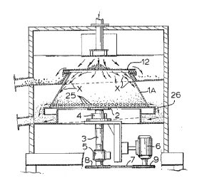
Figure 1 is a section view of a rotating screen
according to one embodiment of the invention, and
Figure 2 is a view similar to Figure 1 of a second
embodiment.
As in the screening device shown and described in
European Patent Application published as EP 0411803 on February
6, 1991, there is provided a hollow drum designated as lA in
Figure 1 of the present application, open at the top and
mounted on a boss 2 which is keyed and bolted on to the upper
end of the shaft 3 supported in bearings 4 and 5 and rotated by
means of an electric motor 6, the drive being transmitted by


, .:
.

~ ~ ~ '7 ;~
3a
a belt 7 passing over pulleys 8 and 9.
A circular piece of woven wire mesh screen cloth 12
having a nominal aperture size of 0.053 mm extends across the
top of the drum lA and is removably secured thereto. The walls
of the drum depend downwardly where it is closed at its lower
end by a skirt member 26. The drum is provided around the lower
part of its periphery with a number of holes 25.
In the embodiment seen in Figure 1 of this applica-
tion the wall of the drum is formed as a frustum of a cone,
diverging towards its lower end where it joins with the lower
skirt member 26. Any of the finer particles in suspension in
the liquid which are flung radially outwardly as they pass
through the screen impinge against the inner face of the wall
as indicated by the arrows X in Figure 1, but tend to strike
the surface at an acute angle. This lessens the tendency of the
particles to adhere to the wall surface.
Further, the divergance of the walls from top to
bottom means that as the drum rotates there is a radial
component of force applied to the particles which causes them
20 to slide down the wall ~ ~ ~ ~ ~ ~
/

W~2/0937~ PCT/GB91/02107
4 2097 3 13

The arrangement is somewhat similar in the second
embodiment illustrated in Figure 2, where the wall of the
drum lB is seen to be curved outwardly from top to bottom.

The same centrifugal effect is present on any
particles striking the wall of the drum and causes them to
slide down the walls towards the holes 25.

To assist in discouraging the adhesion of the
particles to the drum, the inner surface of the wall in
both embodiments may be highly polished or coated with
suitable material, e.g. polytetrafluoroethylene [PTFE].


SU13S~ JTE SI~EET

Representative Drawing
A single figure which represents the drawing illustrating the invention.
Administrative Status

For a clearer understanding of the status of the application/patent presented on this page, the site Disclaimer , as well as the definitions for Patent , Administrative Status , Maintenance Fee  and Payment History  should be consulted.

Administrative Status

Title Date
Forecasted Issue Date 1998-08-04
(86) PCT Filing Date 1991-11-28
(87) PCT Publication Date 1992-05-30
(85) National Entry 1993-05-28
Examination Requested 1994-07-08
(45) Issued 1998-08-04
Deemed Expired 2001-11-28

Abandonment History

There is no abandonment history.

Payment History

Fee Type Anniversary Year Due Date Amount Paid Paid Date
Application Fee $0.00 1993-05-28
Maintenance Fee - Application - New Act 2 1993-11-29 $100.00 1993-10-07
Registration of a document - section 124 $0.00 1993-11-16
Request for Examination $400.00 1994-07-08
Maintenance Fee - Application - New Act 3 1994-11-28 $100.00 1994-10-27
Maintenance Fee - Application - New Act 4 1995-11-28 $100.00 1995-10-25
Maintenance Fee - Application - New Act 5 1996-11-28 $150.00 1996-10-29
Maintenance Fee - Application - New Act 6 1997-11-28 $150.00 1997-10-29
Final Fee $300.00 1998-03-02
Maintenance Fee - Patent - New Act 7 1998-11-30 $150.00 1998-10-13
Maintenance Fee - Patent - New Act 8 1999-11-29 $150.00 1999-10-13
Owners on Record

Note: Records showing the ownership history in alphabetical order.

Current Owners on Record
ECC INTERNATIONAL LIMITED
Past Owners on Record
FALCON-STEWARD, HUGH ROBIN
JONES, THOMAS RICHARD
PHILLIPS, REGINALD LEYLAND
Past Owners that do not appear in the "Owners on Record" listing will appear in other documentation within the application.
Documents

To view selected files, please enter reCAPTCHA code :


To view images, click a link in the Document Description column. To download the documents, select one or more checkboxes in the first column and then click the "Download Selected in PDF format (Zip Archive)" or the "Download Selected as Single PDF" button.

List of published and non-published patent-specific documents on the CPD .

If you have any difficulty accessing content, you can call the Client Service Centre at 1-866-997-1936 or send them an e-mail at CIPO Client Service Centre.


Document
Description 
Date
(yyyy-mm-dd) 
Number of pages   Size of Image (KB) 
Representative Drawing 1998-07-21 1 14
Cover Page 1998-07-21 1 43
Description 1997-11-06 5 198
Claims 1997-11-06 3 81
Abstract 1995-08-17 1 67
Cover Page 1994-04-01 1 22
Claims 1994-04-01 1 38
Drawings 1994-04-01 1 56
Description 1994-04-01 4 157
Claims 1998-06-04 3 81
Description 1998-06-04 5 198
Correspondence 1998-03-02 1 34
Office Letter 1994-08-15 1 48
Examiner Requisition 1997-07-08 2 50
Prosecution Correspondence 1994-07-08 1 39
Prosecution Correspondence 1997-09-17 6 165
International Preliminary Examination Report 1993-05-28 12 340
Fees 1996-10-29 1 50
Fees 1995-10-25 1 51
Fees 1994-10-27 1 44
Fees 1993-10-07 1 26