Note: Descriptions are shown in the official language in which they were submitted.
20g7741
UTILITY VEHICLE CARGO BOX TAILGATE LATCH AND SUPPORT
Background of the Invention
The present invention relates to utility hauling vehicles
and more particularly relates to latches and supports for
tailgates of cargo boxes of such vehicles.
Various hauling vehicle tailgate designs are known which
include a cargo box having a tailgate forming a rear wall
thereof and being mounted for pivoting about a horizontal axis
at its bottom end between raised closed and lowered open
positions. Typically a latch is provided at each upper corner
of the tailgate for retaining the tailgate in its closed
position and a flexible element, such as a cable, is provided
which extends between each upper corner and the upper rear
portion of each side wall of the box for retaining the
tailgate in an open position wherein it forms a horizontal
extension of the bed or floor of the box. These known
tailgate latches and supports include many parts that make
them relatively costly and somewhat complicated to assemble.
Furthermore, in most cases the latch assemblies are not tight
enough to keep the tailgate or latch assemblies from rattling
when the vehicle is operated with the tailgate closed.
Summary of the Invention
According to the present invention there is provided a
cargo box with an improved tailgate latch and support
assembly.
A broad object of the invention is to provide a cargo box
having a tailgate latch and support assembly which overcomes
the disadvantages of the prior art structures.
More specifically, it is an object of the invention to
provide a tailgate latch and support assembly including a
single member mounted between each end of the tailgate and an
adjacent side wall and which functions both as a latch and
support.
A further object of the invention is to provide a
tailgate latch and support assembly at each end of the
tailgate which includes a single member mounted such as to
effect a biasing force which acts between the member and the
2097741
tailgate so as to prevent them from rattling during operation
of the vehicle.
These and other objects will become apparent from a
reading of the ensuing description together with the appended
drawings.
Brief Description of the Drawings
FIG. 1 is a right front perspective view of a utility
hauling vehicle of the type with which the present invention
is particularly adapted for use.
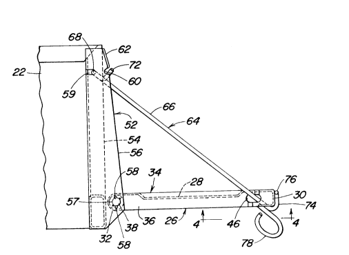
FIG. 2 is a left side elevational view showing the
tailgate supported in its open position by the unitary latch
and support member.
FIG. 3 is a top view showing the left corner area of the
box showing the unitary latch and support member in solid
lines in a position where it has just been unlatched or is
about to be latched, and showing the member in dashed lines in
its latched position.
FIG. 4 is an enlarged view taken along line 4--4 of FIG.
2 but showing only the mounting bracket which forms one end of
the tailgate.
FIGS. 5, 6 and 7 are top, right end and rear views
respectively of the unitary latch and support member shown in
FIG. 3.
Description of the Preferred Embodiment
Referring now to FIG. 1, there is shown a utility hauling
vehicle 10 including a frame 12 supported by four drive wheels
14 and a pair of steerable front wheels 16. Supported on the
frame 12 in a location above the drive wheels 14 is a cargo
box 18. The box 18 includes a horizontal bed or floor 20 and
vertical right and left side walls 22 and a front wall 24. A
tailgate 26 forms a rear wall of the box 18 and is mounted, in
a manner to be described, for selectively closing the opening
defined by the rear edges of the floor 20 the side walls 22.
Referring now also to FIGS 2 - 4, it can be seen that the
tailgate 26, as considered in its upright closed position
shown in FIGS. 1 and 3, includes an upright panel 28 having a
rearwardly and downwardly bent or rolled upper end 30 that is
2097741
substantially inverted J-shaped in cross section and having a
rolled bottom end 32 that is substantially circular in cross
section. Opposite ends of the tailgate 26 (only the left end
being shown in detail) are each defined by a mounting bracket
34 in the form of a bent strap having a main straight portion
36 welded along a given end of the panel 28, including the
tube-like bottom end 32, the straight portion having a hole
receiving a pivot pin 38 which is welded to the bracket 34.
Each pin 38 has a pair of diametrically opposite protuberances
40 spaced inwardly from the outer end of the pin and having a
purpose explained below. Each bracket 34 has an end portion 42
which is offset from the straight portion 36 and terminates in
an end 44 bent at a right angle to the remainder of the
portion 42. The offset portion is spaced from the panel 28
except that the end 44 is welded to the underside of the upper
end 30 of the panel 28. In an area of the bracket 34 where
the offset portion 42 joins the straight portion 36, an
opening 46 is provided which appears in side view (FIG. 2) as
an elongate hole but in top view (FIG.4) as a diamond-shape
due to opposite side portions 48 and 50 of the material
forming the offset and bounding the opening being bent or
offset relative to each other. The purpose of the opening 46
is described below.
The tailgate 26 is mounted to the remainder of the box 18
by structure including a mounting bracket 52 in the form of a
rearwardly opening channel defining the rear end of each of
the side walls 22 and having its web disposed vertically and
joined to inner and outer flanges 54 and 56, respectively,
with the outer flange extending rearwardly beyond the inner
flange in increasing amounts from top to bottom. The
oppositely projecting pins 38 of the tailgate 26 are pivotally
received in holes 57 provided in the outer flanges 56 and
cooperate therewith for defining a horizontal pivot axis about
which the tailgate is swingable between its closed and open
positions. The holes 57 are provided with diametrically
opposite, vertically aligned clearance notches 58. The pin
protuberances 40 are disposed 45 out of phase with the
20977~1
notches 58, the latter serving to permit the tailgate 26 to be
disconnected from the brackets 52 by rotating the tailgate
down 45 from its open position (permitted by first removing
latch and support member 64 from bracket 52) and shifting it
sideways so that the protuberances of the pin at one end of
the tailgate pass through the notches 58 while the pin at the
other end of the tailgate is withdrawn from the hole 57 of its
mounting bracket 52. The tailgate 26 can then be cocked
rearwardly and moved so as to first withdraw the protuberances
40 through the notches 58 and then the associated pin 38 from
the hole 57.
For a purpose explained below, the flanges 56 of each
bracket 52 is provided with a fore-and-aft elongated opening
59 at a location near the top of the bracket and next to the
web. Spaced forwardly from the opening 59 in a rear edge
portion of the flange 56 is a clearance notch or recess 60
which is located just beneath an out-turned wing 62 formed at
the upper rear edge of the flange 56.
Acting together with and mounted between each of the sets
of brackets 34 and 52 at the opposite sides of the box 18 for
defining a combined latch and support structure for
selectively retaining the tailgate in its closed position or
supporting the tailgate in its open position is an elongate
unitary latch and support member 64. Specifically, each
member 64 comprises a formed resilient metal rod having a
straight body section 66 having a length which is
approximately equal to the distance between the openings 46
and 59, respectively in the tailgate and side wall brackets 34
and 52 when the tailgate 26 is in its open position (FIG. 2)
wherein it forms a horizontal extension of the floor 20. A
first hook or retaining portion 68 includes a backturned
section 70 which parallels the body portion 66, the backturned
section being joined to an end section 72 which is disposed at
a right angle to the backturned section. The hook or
retaining portion 68 extends through the opening 59 in the
bracket 52 with the flange 56 then being between the sections
66 and 70. Joined to the opposite end of the straight section
- ~ 2097741
66 is a second hook or retaining portion 74 which makes an
acute angle with the section 68 and terminates in an out-
turned end 76.
When the tailgate 26 is in its open position, as shown in
FIG. 2, it can be seen that the latch and support member 64
supports the tailgate with the hook or retaining portion 76
embracing the formed end 30 of the tailgate. When it is
desired to close the tailgate 26, the latter is lifted into
abutting relationship with the rear ends of the side walls 22.
The latch and support members 64 will then be in substantially
horizontal, rearwardly projecting positions. The operator
will then latch one then the other of the members 64 by
grasping a ring-like handle 78 welded to the straight portion
66 at a location adjacent the second hook 74 and swinging the
free end of the member 64 toward an inward location of the top
end 30 of the tailgate and inserting the end 76 in a hole 80
provided there. It is to be understood that when the member
64 reaches the solid line position shown in FIG. 3 wherein it
is just about to pass beneath the tailgate upper end 30, the
straight portion 66 comes into contact with the edge of the
opening 46 in the tailgate bracket 34. Further movement of
the member 64 causes the latter to flex and be resiliently
loaded. When the member 64 is released with the end 76 placed
in the hole 80, some of the load remains so that the contact
points of the member 64 with the tailgate and side wall
brackets 34 and 52 remain tight while the tailgate 26 is
biased towards its closed position. Thus, it will be
appreciated that each latch and support member 64 works in a
manner to reduce rattling of the member and associated
tailgate end during the operation of the vehicle 10 with the
tailgate 26 in its closed position.