Note: Descriptions are shown in the official language in which they were submitted.
2~97788
MEI~IOD FOR PRODUCING PREFABRICATED FOAM-INSULATED
WALLS
FIELD OF INVENTION
This invention relates to a method of producing foam-filled stud
S walls.
BACKGROUND OF THE INVENTION
It has long been known that a foam-filled wood stud wall is very
desirable from an insulation (i.e. heat transfer) viewpoint, and various methodshave been used in the past to produce such walls.
No suitable method has yet been developed to facilitate rapid
and efficient prefabrication of such walls on an assembly-line basis. The
present invention is directed toward providing a suitable assembly line method
for implementing the method for producing prefabricated foam-filled walls.
The type of wall intended to be filled is the type commonly used
in wood frame construction, i.e. a wall having a base plate, a top plate, windowand door openings, and a number of spaced vertical studs, the plates and studs
most commonly being either nomin~l two-by-four or two-by-six lumber.
However, this invention is not limited either to specific stud sizes or spacings,
nor to any specific stud material.
In the prior art, urethane insulation has been applied on site to
standing stud walls, typically by spraying a spray-type foam onto the wall and
building up an insulating layer roughly an inch at a time. As spray-type foams
are highly exothermic, the layers of insulation must be built up gradually. Thistype of system is generally cumbersome, messy and may product an uneven
2S surface with no certainty that all voids, including corner cavities are filled.
*
2097788
- 2 -
Another attempted solution in the prior art has been to inject
measured amounts of foam between panels, but this is difficult or impossible
to do in the case of prefabricated stud walls, especially when cle~ling with
varying wall sizes. Injecting an incorrect amount of foam may result either in
5 voids in the insulation, or in the wall being forced apart by the expanding
foam. The latter problems may possibly be avoided by utili7ing a full press on
both sides of the wall, but in addition to requiring more elaborate equipment,
this also means that non-standard wall sizes cannot be readily accommodated,
nor can window openings and the like.
In the prior art, various types of equipment have been used for
injecting foam into double-membrane panels such as those found in metal
garage doors, for example. Such systems suffer from a number of serious
drawbacks which prevent or severely restrict their applicability to stud walls.
These drawbacks include the fact that a complete filling may not take place,
15 and may not even be possible, if the panel includes window and door
openings. Another serious problem with this type of system is that, since both
front and rear panels must be in place to contain the foam, either a finished
interior surface, or a superfluous interior panel (to be covered later by a
finished surface) must be provided. If a finished interior surface such as
20 gypsum board or "drywall" is installed at the plant location, further handling
of the panel is made far more difficult. This type of panel would not only
weigh more, but would need to be handled with great care in order to avoid
cl~m~ging the finished surface.
A method for producing a prefabricated insulated wall panel is
2097788
- 3 -
disclosed in U.S. patent number 4,409,768 granted to Boden in October 1983.
The preferred embodiment of this invention employs multiple dams to contain
the foam introduced into a wall. A single dam is used to cover the area to be
filled. A stud wall is placed into a backplate and then a series of plates is
S placed upon the stud wall. Although a satisfactory wall may be produced,
Boden is not particularly well suited for production line methods of
manufacturing. The use of a single dam covering a full stud wall as the foam
sets is highly inefficient and not cost effective.
A method for insulating walls is disclosed in U. S. patent number
10 4,093,411, granted to Lee in June 1978. Lee teaches a process for covering a
surface with foam using a machine which travels along the surface. The wall
produced will have effective heat transfer properties but may not be
s~ f~ctory. If the studs are warped or vary in width, the wall will not be
unirolm nor will a planar surface be achieved. Further, the foam material will
15 exude from the stud cavity which will require removal.
Lee discloses an apparatus having a continuous or endless belt,
and does not suggest the use of a single plate moved along the stud wall in
discrete steps with a delay between such steps to allow for setting of the foam.
It should be noted that although Lee shows a pressure plate behind the belt,
20 it merely serves to limit the expansion of the foam, and has no means for
urging the belt into contact with underlying studs so as to straighten any
mic~lignment or to adjust for varying thickness.
Applicant has found that after the foam has been injected into
the stud wall and allowed to cure, the foam will continue to expand for about
20977~8
_ - 4 -
24 hours by about 1% - 2~o of its initially cured volume. This phenomenon
is known as "slow grow". The foam will bulge outwardly from the stud cavity
preventing a sheet of drywall to be applied directly thereto. Either the foam
must be continuously restrained to prevent the foam from expanding or the
S excess foam must be removed mechanically. In either case, the efficiency of
manufacturing is greatly limini~hed.
In the former case, a double-framed membrane can be used to
restrict the expansion of the foam, which adds material costs to the finished
product. If the inner surface is to be left open, the stud wall must be kept in
10 a press for up to 24 hours while the foam fully cures, which greatly restricts
the production speed of a finished wall product.
In the latter case, a considerable labour cost is added to the
finished product to remove the excess foam to present a planar surface.
Further, sanding of the foam releases foam particles and dust into the air
15 which requires special health and safety precautions to be exercised.
It is highly desirable to have a method which permits the filling
not only of uniform size wall sections without window openings or the like, but
also the filling of varying sizes of wall sections with varying sizes and locations
of window openings. It is also highly desirable to have a method which
20 permits the filling of walls without requiring the presence of any interior panel,
finished or otherwise.
It is also desirable to have a method which presents a finished
surface substantially planar with the studs, while removing a minimum of
excess foam.
2097788
SUMMARY OF THE INVENTION
The present invention is therefore directed at producing an
insulation-filled stud wall which has one open side, namely the interior side.
During the process of manufacture, a half-completed stud wall is introduced
S into an apparatus comprising a backplate and a moveable dam having a
removable sheet and a compressible membrane. The exterior sheztthin~ of the
stud wall is placed against the back plate. The stud wall is backed with any
suitable exterior she~tl~ine~ such as asphalt-impregnated fibre board. The
removable sheet is draped over the interior of the stud wall. The comprcssible
10 membrane is placed over the removable sheet and the moveable dam urges
the backplate, stud wall, removable sheet and compressible membrane
together. The compressible membrane will form a seal between the dam and
the studs and will be urged into the wall cavity reducing the volume of the
cavity.
As will be explained in greater detail herein, a foam or foam-
forming ll~ u~e is introduced between the she~thing and the moveable dam
having the removable sheet and the compressible membrane which is
temporarily positioned against the interior side of the studs. The foam or
foam-forming mixture is introduced by a "spray-pour" method. In this type of
20 method, a spray-type urethane foam is injected between the exterior she~tlling
and the dam using an atomizing spray nozzle having a tube to direct the
trajectory of the spray. The foam is then permitted to rise freely between the
sheathing and the dam and is allowed to set.
After allowing sufficient setting time to elapse, the dam is moved
20g77~8
- 6 -
to the next upper unfilled section of the stud wall while the removable sheet
and the col,lplessible membrane are unrolled in advance of the moveable dam
and the next batch of foam or foam-forming mixture is introduced into the
wall. The wall can therefore be filled in a series of spray-pours.
S In accordance with the present invention, a method is provided
for filling a she~thing-backed, one-side-open stud wall with foam using an
apparatus comprising a main frame, including a substantially vertical backplate
against which the she~thing bears; a dam having on one face thereof a
removable sheet and a compressible membrane and extending parallel to the
10 backplate, moveable towards and away from and vertically with respect to the
backplate; draping the removable sheet and compressible membrane over the
stud cavity; a means for holding the dam against the stud wall when the stud
wall is positioned with its shez~thing against the backplate; and a means for
moving the dam vertically while it is so held against the stud wall while
15 unrolling the removable sheet and the compressible membrane.
One side between the backplate and the dam constitutes a stud
wall entrance area and the other side constitutes a stud wall exit area. A stud
wall may be introduced at the entrance area and positioned between the
backplate and the dam. The dam may then be moved against the bottom
20 portion of the open side of the stud wall and held there. Foam may then be
introduced between the backplate and the dam to fill the stud wall
therebetween. After a predetermined time has been allowed for the foam to
set, the dam may be moved upwardly while unrolling the removable sheet and
the compressible membrane in advance of the dam, additional foam may then
20~7788
- 7 -
be introduced to fill a higher portion of the stud wall, and so on to completion
of filling. Once the stud wall is filled the dam may be moved away from the
backplate, and the filled portion of the stud wall may then be advanced
towards the exit area.
S In the present invention, at least a portion of an unfilled
she~thine-backed stud wall in inserted between a backplate and a dam. The
stud wall is introduced in such a manner that the shezlthing lies against the
backplate and the dam face having the removable sheet and the coll,plessible
membrane straddles at least two studs of the stud wall. The dam is mounted
10 for movement towards and away from the backplate, the movement being
substantially parallel to the backplate. The dam is urged against the bottom
portion of the open side of the stud wall, co~lplessing the compressible
membrane, against any resistance due to nonlinearity or mi~lienment of the
studs, to a predetermined distance from the backplate, so as to trap the stud
15 wall between the dam and the backplate. The movement of the dam relative
to the backplate el~sules uni~ol~ y of the front of the studs which ensures
that if the studs are warped or vary in width, they will be forced back into
contact with the front surface of the sheathing to ensure that the foam does
not escape from between the rear surface of the stud and the she~thine. The
20 movement also ensures that the foam does not exude from the cavity.
Further, the dam will compress the compressible membrane at
the studs. The compressible membrane will act as a further sealant to ensure
that the foam does not exude from the stud cavity between the studs and the
dam. More importantly, the membrane between the studs will not be
20g778~
~_ - 8
compressed, thereby reducing the volume of the stud cavity.
A foam or a foam-forming ~ ure is introduced between the
she~thine and the dam face having the removable sheet and the colllpressible
membrane to fill the portion of the stud wall therebetween with foam. A
S predetermined setting time for the foam is allowed to elapse. The dam is
moved along the stud wall as the removable sheet and the compressible
membrane is unrolled in advance of the dam, to dam a different unfilled
portion of the wall.
The steps of the process from the introduction of the foam to
the movement of the dam are repeated until the wall is completely filled. The
dam is then withdrawn from the stud wall, the removable sheet is removed and
discarded and the filled portion of the wall is removed from between the
backplate and the dam.
In accordance with one embodiment of the invention, there is
provided a method for filling a she~thine backed one-side-open stud wall with
foam. The method comprises the steps of:
a. introducing at least a portion of the unfilled stud wall between
a substantially vertical backplate and a substantially vertical dam having
on one face thereof a removable sheet and a compressible membrane,
with the she~thine against the backplate, and such that the dam
straddles at least two studs defining a cavity;
b. moving the dam towards the bottom portion of the open side of
the stud wall to a predetermined distance from said backplate
compressing the colllplessible membrane against the studs and reducing
20g778~
- 9 -
the volume of the cavity;
c. introducing a foam or foam-forming ~ L~re to the bottom of
the cavity and allowing the foam or foam-forming ~ Lule to expand
and fill the stud wall with foam;
S d. unrolling the removable sheet and the compressible membrane
in advance of the moveable dam;
e. moving the dam upwardly to expose the foam after a
predetermined setting time;
f. introducing additional foam or foam-forming mixture to fill a
higher portion of the stud wall with foam;
g. repeating steps d, e and f on to completion of filling;
h. moving the dam away from the stud wall removing the
removable sheet and discarding; and
i. advancing the filled portion of the stud wall from between the
backplate and the dam.
In accordance with another embodiment of the invention there
is provided a method filling a she~hing backed, one-side-open stud wall with
foam, said method colll~lising the steps of:
a. introducing at least a portion of the unfilled stud wall between
a backplate and a dam having on one face thereof a removable sheet
and a colllplessible membrane, said dam mounted for movement
towards and away from said backplate and parallel to said backplate,
with the sheathing against the backplate, and such that the dam
straddles at least two studs of said stud wall;
20S7788
- 10-
b. urging the dam against the bottom portion of the open side of
the stud wall and against any resistance due to nonlinearity or
mi~lignment of said studs so as to trap said studs between said dam
and said backplate and to colllpress said compressible membrane
against said studs;
c. introducing a foam or foam-forming mixture between the
she~tlling and the dam having the removable sheet and the
compressible membrane to fill the said portion of the stud wall
therebetween with foam;
d. allowing a predetermined setting time, unrolling the removable
sheet and the compressible membrane and moving the dam along said
two studs to dam a different unfilled portion of the stud wall;
e. repeating steps c and d until completion of filling;
f. retracting the dam from the stud wall, removing said removable
sheet and discarding;
g. removing the filled portion of the stud wall from between said
backplate and said dam;
h. Iowering said dam and recovering said compressible membrane
to a start position.
Further features of the invention will be described or will
become apparent in the course of the following detailed description.
209778~
11 -
BRIEF DESCRIPTION OF THE DRAWINGS
In order that the invention may be more clearly understood, the
preferred method and the preferred embodiment of the apparatus will now be
described in detail by way of example, with reference to the accompanying
5 drawings, in which:
Fig. 1 is a side view of the apparatus;
Fig. 2 is a front view of the apparatus;
Fig. 3 is a top view of the apparatus;
Figs. 4a, 4b and 4c are top, front and side views, respectively, of
the main frame of the apparatus;
Figs. 5a, Sb and 5c are top, front and side views, respectively, of
the carrier unit on the apparatus; and
Figs. 6a, 6b and 6c are top, front and side views, respectively, of
the dam assembly of the apparatus.
15 DETAILED DESCRIPTION OF THE PREFERRED EMBODIMENT
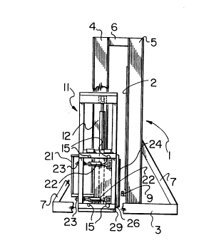
Referring to the drawings, the prerelled embodiment of the
apparatus of the invention has a main frame 1, including a vertical backplate
2 against which the she~thing bears. A carrier unit 11 moves up and down on
the main frame 1, and carries an assembly 21 which is moveable towards and
away from the backplate 2. The dam assembly 21 includes a dam 24 parallel
to the backplate 2.
Holding means are provided for holding the dam assembly 21
and thus the dam 24 at a specified distance from the backplate 2, via hydraulic
cylinders 22 which have threaded (and therefore adjustable) end-mounts 23.
2097788
- 12-
The carrier unit 11, and thus the dam assembly 21 and dam 24,
can be repositioned vertically while the dam assembly 21 is held in its
holi;Golllal position, by virtue of hydraulic lift cylinders 12 between the main
frame 1 and the carrier unit 11. Eight cam bearings 15 guide the carrier unit
S 11 on the front vertical columns 4 of the main frame 1.
The main frame, shown most clearly in Figs. 4a, 4b and 4c,
comprises a base 3, two front vertical columns 4, two rear vertical columns 5,
top cross beams 6 connecting the front and rear vertical columns, brace
members 7 for the front and rear vertical columns, and a series of crosspieces
10 8 between the two rear vertical columns S, to support the backplate 2 (not
shown in Fig. 4b.).
The carrier unit 11, shown most clearly in Figs. Sa, Sb and 5c,
comprises an open box frame 13. The upper side members of the frame 13
include mounting points 14 for the hydraulic lift cylinders 12, which are
15 attached at their lower ends to the base 3 of the main frame 1. There are two
lift cylinders 12, one at each end of the carrier unit 11.
The dam assembly 21, shown in Figs. 6a, 6b and 6c, comprises
the dam 24 and a work platform 25, with safety rail 25a. Mounted on the
work platform are various controls to be described later. The dam 24 itself
20 is appr~-xi~ tely 36 inches high by 74 inches wide in the preferred
embodiment.
It is important that the dam be held in position against the studs
in order to ensure unirollll applied pressure throughout its frontal area.
209778B
~_ - 13 -
The invention is therefore designed either to apply constant jig
pressure by means of regulated hydraulic pressure, or preferably, to prevent
the advance of the dam past a pre-set dimension (about 4 inches on a 2x4 stud
wall). This distance should preferably be adjustable to a close tolerance at
5 each corner of the dam to suit the material being used. This is accomplished
by the use of four hydraulic cylinders 22.
Hydraulic actuation is used in the preferred embodiment, but it
should be understood that pneumatic or other suitable actuation could be used
if desired.
The four cylinders 22 have a threaded adjustment 23 at the back
end of the cylinder so that the cylinder may be fully extended when the desired
wall thickness is achieved. With this "limited travel" design, the amount of
total force is not critical as long as it exceeds the force of the expanding foam,
since the advance of the cylinders is restricted so as to prevent undue crushing
15 or compressing of either the sheathing or stud components of the wall.
Preferably, the design range of adjustment is sufficient to accommodate wall
thickness from 3 inches to 7 inches so that walls made from 2x3, 2x4 or 2x6
can be manufactured.
The design preferably includes a pneumatic accumulator with an
20 adjustable unloading valve rather than a dead-weight accumulator. This is
easier to adjust although not providing as constant a loading.
The opening at one side between the backplate 2 and the dam
24 constitutes a stud wall entrance area 41, and the other side constitutes a
stud wall exit area 42.
20~77~8
- 14-
In one method, a stud wall, comprising a base plate, a top plate,
spaced studs, window and door openings, bearing headers, and exterior
she~thin~ is introduced at the entrance area 41 and positioned between the
backplate 2 and the dam 24, supported on rollers 9. The stud wall is
S positioned in such a manner that the dam 24 straddles at least two studs.
In the stud wall, provision for wiring may be made before filling,
by positioning switch and receptacle boxes as desired and running conduit to
them, the conduit in each case passing down through an opening in the base
plate. Alternatively, passageways and openings for wiring and receptacle
10 switch boxes may be mechanically excavated in the foam once the cavity has
been filled.
The dam 24 is then moved towards the bottom portion of the
open side of the stud wall and against any resistance due to nonlinearity or
mic~lignment of the studs, to a predetermined distance from said backplate,
15 so as to trap the studs between the dam and the backplate 2. The dam 24 is
held at that distance from the backplate 2.
A foam or a foam-forming mixture is then "spray-poured"
between the she~thing and the dam 24 by a worker standing on the work
platform 25. The foam or foam-forming mixture is manually sprayed into the
20 wall by extending the spray gun past the top edge of the dam 24. This area
of the stud wall is filled to an intended depth of ap~ro~ ately 1.5 feet.
The equipment to "spray-pour" the foam or foam-forming
mixture into the wall cavity is a conventional spray apparatus. The spray gun
has a conventional atomi7ing nozzle for delivering foam. However, a length
2097~88
- 15 -
of plastic tubing, ap~r~)xi~ tely 2 inches, is applied over the nozzle and the
foam or foam forming ~ re is sprayed therethrough.
The tubing prevents the spray from "f~nnin~" outwardly so as to
deliver the foam or foam-forming mixture to the bottom of the cavity. If a
5 tube is not used, the foam or foam-forming mixture has a tendency to begin
expanding from the shezlthing or the removable sheet forming a bridge across
the cavity preventing sufficient amounts of foam or foam-forming mixture to
be delivered thereto creating a self-void.
After allowing a predetermined setting time, for example one
10 minute, the dam 24is moved upwardly a~pr~-xi"-~tely 1.5 feet to expose the
set foam or foam-filling mixture is then introduced into the unfilled portion of
the stud wall which is straddled by the dam.
The steps of introducing the foam, waiting for the foam to set,
and then moving the dam, are repeated until the wall is filled. The dam 24
is stopped a~r. xilll~tely two inches short of the top of the wall for the final
spray-pour. This allows any excess foam to rise out of the opening.
The same procedure is used for under window openings, the
dam being stopped a~plnxil,-~tely two inches short of the bottom plate of the
window opening. The excess foam in each case is then trimmed off.
The foams presently used are rigid polyurethane foams such as
those sold by Stanchem C.I.L as experimental products nos. 240 N C and 12-
129/lX. The foams have an expansion factor of ap~ru~lllately 30 to 1 by
volume. The catalysts have been altered to slow the kinetics of the foam.
With the 240 NC foam, the foams have a cream time of 6 to 8 seconds and
2097788
- 16-
tack-free time of 25 seconds.
The slower expansion of the foam reduces the exothermic
characteristics of the foam as well as reduce the incidence of self-voids in the
~mished wall product. While rigid polyurethane foam is presently preferred,
5 the application of the present invention is not limited to the specific type of
foam to be employed.
So that the surface of the dam 24 does not scrape against the
foam as it is elevated, and so that the foam is prevented from adhering to the
dam, a removable polyethylene sheet 50 is draped over stud wall and between
10 the dam 24. A polyethylene sheet of 4 mil thickness has been found have
suitable non-adhering properties when used with the preferred foam. Thicker
polyethylene may be used but at additional costs.
Polyethylene normally is available in rolls having a width to
match the width of the dam. Sheet 50 is draped over the stud cavity and
15 allowed to hang from the top of dam assembly 21. The leading edge of the
sheet 50 is extended until it extend slightly beyond the base plate of the stud
wall. The operator unwinds the roll as the dam 24 rises to completely cover
the stud cavity. Once the foam has cured and the dam is withdrawn from the
backplate, the sheet 50 may be cut off from the roll and removed from the
foam and discarded.
A compressible membrane 26 is positioned over the face of the
dam. One end is attached to a bar 29 running across between the base
members of the main frame 1 and the other is spring-wound onto a roll 27.
The membrane is thus unrolled as the dam 24 rises, and is retrieved on the
2097788
- 17-
roll as the dam descends.
In the ~refe,led embodiment, membrane 26 is an area of
indoor/outdoor carpet. The compressible properties of indoor/outdoor carpet
surprisingly make it ideal for this application. When colllpressed between the
S dam and the stud, the carpet acts as a seal preventing the foam from exuding
from the stud cavity. For the area of carpet covering the stud cavity and not
compressed, the carpet reduces the volume of the stud cavity by ap~r. .,~ tely
2%. Accordingly, after the foam finally cures and expands, a planar surface
substantially level with the level of the studs results. A millimulll of excess
10 foam will exude from the last pour and will be required to be trimmed.
Once the stud wall is filled, the dam 24 is disengaged and moved
away from the backplate 2, the carrier unit 11 is lowered, the removable sheet
50 is removed and discarded and the wall is moved along through the
apparatus in the direction of the exit area 42 until it reaches the next section
15 of stud wall to be filled. The maximum width which can be filled in
any series of spray-pours depends on the width of the dam 24. The width of
the dam can be varied at the design stage to suit the desired throughput of the
machme.
In the preferred embodiment, a 74 inch width dam can thus be
20 filled. Any height (depth of spray-pour) can be accommodated from zero to
the top of the dam at the top of its travel.
The preferred method therefore comprises the steps of
introducing a sheathing backed, unfilled stud wall between the backplate 2 and
the dam 24 having on one face thereof compressible membrane 26 and
20-97788
- 18-
removable sheet 50, urging the dam 24 towards the bottom portion of the
open side of the stud wall and holding it at that distance from the backplate
2; introducing foam or a foam-forming mixture between the sheathing and the
dam 24 having on one face thereof compressible membrane 26 and removable
5 sheet 50 to fill the cavity therebetween; allowing a predetermined setting time
to elapse; unrolling membrane 26 and sheet 50; moving the dam 24 along two
studs to dam a different unfilled portion of the stud wall; introducing foam or
foam-forming u~ ure to fill this section of the stud wall; repeating the four
immediately preceding steps until the stud wall is filled; releasing the dam 24
10 and retracting it from the backplate 2; removing the removable sheet 50 and
discarding; removing the filled portion of the stud wall from between the
backplate and the dam and moving the same towards the exit area 4; and
lowering said dam and retracting the compressible membrane 26 to a start
position.
The method used at the top plate or header of the stud wall is
to stop the dam therebelow and introduce the foam or foam-mixture allowing
it to expand outwardly between the dam and top plate or header. The foam
will fully occupies the volume below the top plate or header and the excess
foam can be trimmed after curing and before moving the dam further
20 upwardly.
The method can further include the steps of introducing an
adjacent portion of an unfilled part of the she~thing-backed stud wall laterally
between the backplate and dam; and repeating the steps until the stud wall is
fully filled with foam.
_ 2097788
- 19 -
Once the stud wall is fully filled with foam, the wall can be
removed from the apparatus and allowed to finally cure. The compressible
membrane has reduced the volume of the stud cavity and therefore the form
may continue to ~Yp~nd to its final volume without bulging outwardly beyond
S the plane defined by the studs.
Further, the foam will act as a brace for the studs. Since the
studs were urged between the dam and the backplate to realign the studs, the
foam will m~int~in the studs in an aligned position. The end result is a
substantially true stud wall presenting a substantially planar surface ready to
10 receive drywall or other panelling.
There is normally no provision made for plumbing, as this would
usually be positioned on the interior walls of the structure. The same
techniques as those used for electrical wiring could be used for installing
plumbing.
Suitable controls are provided for raising and lowering the dam.
A number of fail-safe devices, as subsequently described in more detail, are
provided to ensure operator safety.
The hydraulic system (not illustrated) uses a tandem hydraulic
pump which consists of two separate pumps housed in a common housing and
20 driven by one 5 horsepower electric motor. This allows independent operation
of two hydraulic systems "A" and "B", without adverse interaction between the
two. All components are rated at 1,800 psi or more and have a 4 to 1 safety
margin to absorb shock loads, etc.
System A involves one three-position control valve to operate
20g7788
- 20 -
the lift cylinders 12. The valve is electric solenoid controlled from the
operator's platform. The two lift cylinders are protected in a "fail safe" mode
by pilot-operated check valves "solid connected" to the bottom port. This
prevents the cylinders from lowering either by accident or line failure. The
S platform can only be lowered when "powered down" with the pump operating
and the solenoid valve engaged. There is a flow control valve on the raise side
of the cylinders that allows the lift speed to be varied from zero to its
ma~imulll of 2" per second. The lowering speed is fixed at 3.9" per second.
The lift mech~ni~m has a possible lift capacity of 17,000 pounds however the
10 normal lift is expected to be about 6,000 lbs.
System B involves an unloading valve and accumulator providing
a constant (adjustable) force on the dam which can be limited by the
unloading valve adjustment to a value between 12,000 and 22,000 pounds
force. The dam is advanced by a ''two-hz~n~iecl~ pair of push buttons (i.e., for
15 safety, controls which can only be activated by the operator using both hands
on the buttons) until a limit switch at the fully extended position bypasses the
advance buttons and holds the dam in its advanced position. If the push
buttons are released during the advancing mode, the dam will return to its full
open position. The dam is normally returned by a separate return push
20 button. An indicator light will monitor the position of the dam. The speed
of the dam is a~pluxinlately 1 inch per second advance and a~proxi"~tely 1.4
inches per second return. There is no provision to stop the dam and hold it
at any position other than fully advanced or fully returned.
The electrical system is controlled from a control panel mounted
2097788
- 21 -
on the operator's work platform 25. The panel includes the following switches
and indicator lights:
Main pump relay switch: This switch starts the hydraulic power
unit and lights an indicator light. The power unit can also be turned on and
S off at the unit.
Control power switch: This switch activates the control switches
that are used by the operator, also shows on an indicator light.
"Raise-lower" switch: Three position toggle switch that will raise
or lower the platform and dam. Limit switches stop unit at top and bottom.
Dam safety switches: Forward movement of the dam is
controlled by two push buttons, requiring operator's two hands to move the
dam forward. When the dam is fully extended an indicator light will come on
and the buttons can be released; the dam will stay advanced under pressure.
If the buttons are released (either button) before the light comes on, the dam
15 will return to full open position.
Dam return switch - One push button that is held only until the
indicator light goes off, the dam will then return on its own.
Options - Lights, fans etc. could be controlled either from the
platform or from a floor panel.
Also to ensure operator safety and the safety of others in the
plant, a suitable fume exhaust system is provided, and the use of personal
protective equipment as well as positive pressure breathing apparatus by the
human operator is stipulated.
This method is ideally suited to an assembly line for producing
20g7788
- 22 -
a high volume of product, with the advantage that non-standard shapes are
easily accommodated, so that each wall section can be custom-made.
Because the interior of the wall is unfinished, no special care is
required in handling the walls and moving them to the job site. Once the
5 walls are erected, gy~sulll board or "drywall" can be installed on the interior
surface of the wall in the conventional fashion. Minor abrasions or
indentations to the wall will not affect the thermal characteristics and will be
concealed by gy~ulll board or "drywall", when it is applied.
The above description relates to the preferred method by way
10 of example only. Many variations on the invention will be obvious to those
knowledgeable in the field, and such obvious variations are within the scope
of the invention, whether or not expressly described.
For example, as mentioned above the dam could be advanced
and held in place by constant hydraulic force, though for the reasons specified
15 above, holding at a fixed distance is superior.
Also, the rise of the dam could be continuous rather than step-
wise, the rate of the rise being coordinated with the spray-pour rate to provide
adequate dwell time.
Instead of single-cavity manual spray-pouring, a multiple-nozzle
20 head could be used to spray several cavities at one, and/or the spraying itself
could be automated. Either or both of these options would be especially
feasible for standardized wall sections, rather than "custom" sections.