Note: Descriptions are shown in the official language in which they were submitted.
;~(39'~
- MOWER BLOWER TRASH GUARD
Background of the Invention
1. Field of the Invention
The present invention relates to blowers which are used
with grass mowing decks for assisting in blowing grass from
the deck, through a delivery tube and to a bagger. More
specifically, it relates to an anti-wrap structure to retard
accumulation of trash around the blower fan shaft and
bearings.
2. Description of Related Art
Multi-spindle mower decks carrying a plurality of blades
are commonly utilized for mowing lawns and similar types of
vegetation. These decks are capable of cutting a large swath
of material as they are moved across the ground and are
typically used with baggers or material collection systems.
Since the multi-spindle decks cut a large volume of
material, and it must be blown through the ductwork to the
collector, it is often desirable to provide a blower that can
assure sufficient air and material flow to the collector.
Typically, these blower assist devices are mounted either
adjacent to the deck or in the tube between the deck and the
collector.
When they are mounted intermediate the tube, the
productivity of the fan blade can be improved since the
material can be fed into the center portion of the blower fan
blade to reduce clogs in the chamber the blade is housed
within. Since the desired trajectory of material as it feeds
into the fan blade is perpendicular to and adjacent the axis
of the fan blade shaft, it has been found helpful to remove
the bearing support structure for the blade shaft by
cantilevering the shaft, supporting it only at the end
opposite the material inlet. This reduces the shaft support
structure about which material can collect and cause
blockages.
When blower assists are mounted in the tube between the
mower deck and the collector, however, blockages can occur
2097853
within the tube leading to the blower. Therefore, it is often
desirable to locate the blower assist adjacent to the mower
deck to receive the material from the mower deck and propel it
upwardly through the ductwork to the collector means.
Locating the blower adjacent the side of the mower deck not
only increases the width of the mower deck by the size of the
blower structure, which can make mowing around obstacles more
difficult, but it also reduces the efficiency of the fan blade
since the cut material from the mower deck feeds into the fan
blade below its shaft axis due to the necessity of mounting
the blower low to the ground and adjacent the exit opening of
the mower deck.
To improve the inlet flow of material to blowers mounted
adjacent the mower deck, it has been known to cantilever the
shaft supporting the fan blade so that the throat feeding the
material to the fan blade from the mower deck can feed the
material close to the axis of the shaft. In an attempt to
also reduce the overall width of the deck and blower, the
bearing which supports the cantilevered shaft has been mounted
inside the housing supporting the fan blade and in the chamber
within which the fan blade operates. Locating the bearing
inside the fan chamber, however, has resulted in the problem
of wrapping of grass, straw and other material around the
bearing supporting the shaft, causing a reduction in the
bearing life and increased down time for the blower.
It would, therefore, be desirable to provide a blower
assist structure mounted adjacent a multi-spindle mower deck
wherein that structure included a fan blade mounted in a
cantilevered fashion to facilitate the desirable flow of
material to the blade and with the shaft bearings located
within the housing to reduce the deck and blower width. It
would further be desirable to provide an anti-wrap structure
that would minimize the wrapping build-up of material around
the bearing which is mounted within the housing.
Summary of the Invention
Accordingly, there is provided herein a blower assist
structure mounted adjacent a multi-spindle deck. The blower
~y l
2097~53
fan blade is cantilevered and carried by bearings supporting
only one end of the fan blade shaft. The fan shaft is
unsupported at its blade end to enhance entry of cut material
from the mower deck and eliminate material build-up around
that end of the shaft.
One of the support bearings is mounted within the blower
housing. Surrounding that bearing within the housing is an
anti-wrap structure designed to minimize the accumulation of
material around the bearing which could reduce the bearing
life and increase down time of the machine for removal of
wrapped material or replacement of bearings.
The anti-wrap structure includes a first sleeve-like ring
supported by the housing around the bearing to insulate it
against movement of grass, straw and similar material into the
area where it seats on shaft. The anti-wrap structure further
includes a ring projecting axially from the fan blade to
overlap the sleeve-like ring and inhibit movement of the straw
and similar material down and into the bearing between the fan
blade and the bearing. Additionally provided on the sleeve-
like ring and projecting radially outwardly therefrom is astationary divider ring that is positioned within the terminal
portion of the overlap ring to inhibit axial movement of
material into the space between the fan blade and the bearing.
With this structure there is provided a barrier or dam
against which material that would tend to migrate between the
fan blade and the housing would be prevented from wrapping
around the bearing and shaft. Since the sleeve and divider
ring are stationary and surround the bearing, material can not
easily reach the bearing. Further, the overlapping ring
carried on the fan retards entry of such material into the
bearing and shaft interface.
With this structure an improved blower assist is provided
for multi-spindle decks adjacent their outlet and enhanced
life of the bearing is facilitated with a reduction in machine
down time.
Brief Description of the Drawings
X
~o~ 3
~ Fig. 1 illustrates a vehicle, such as a lawn and garden
tractor, carrying a multi-spindle mower deck, a grass
collector and a blower adjacent the deck.
Fig. 2 illustrates in side view the structure depicted in
Fig. 1.
Fig. 3 illustrates an enlarged partial plan view of the
blower assist structure with the fan blade and its supporting
structure being shown in phantom.
Fig. 4 illustrates an enlarged side view of the blower
inlet, fan blade, shaft and the anti-wrap structure.
Fig. 5 illustrates a side view of the fan blade and its
shaft including the shaft's flat sided configuration.
Fig. 6 illustrates the fan blade which is molded onto the
shaft.
Fig. 7 illustrates a prior art blower, fan blade and
housing arrangement.
Description of the Preferred Embodiment
Looking first to Figs. 1 and 2, there is illustrated a
vehicle 10, such as a lawn and garden tractor, carrying a
multi-spindle mower deck 12 for cutting grass. Carried at the
rear of the tractor 10 is a bagger or collection means 14 and
carried adjacent the mower deck 12 is an auxiliary blower 16
for assisting in conveying cut vegetation, such as grass,
through a duct means 18 and to the collector 14.
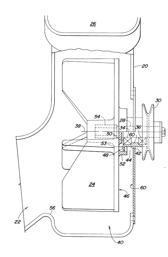
Looking now to Figs. 3 and 4, we find enlarged views of
the blower assist 16; Fig. 3 illustrating it in a plan view
and Fig. 4 illustrating it in an end view taken along lines 4-
-4 of Fig. 3.
As shown in Fig. 3, the blower assist 16 is carried at
the one side of the multi-spindle mower deck 12 and includes a
blower housing 20 which receives material through a throat 22
(see Fig. 4) coupled with the deck 12 for movement by a fan
blade 24 up and to the blower outlet 26 which is connected to
the duct means 18.
Driving the fan blade shaft 28 is a pulley 30 which in
turn is driven by a belt means 32 interconnected with one of
the driven spindle pulleys carried on the mower deck 12. For
;~0~ 3
~urposes of the present invention, this drive means is not
discussed in detail.
The fan blade 24 is preferably comprised of a plastic-
type material which is molded to a hex-shaped shaft 28 (see
Figs. 5 and 6) that in turn is carried in a cantilevered
fashion on a set of bearings 34 and 36 at one end, one set of
the bearings 34 being positioned inside the blower housing 20
and one set 36 being positioned outside the blower housing 20.
The shaft 28 also carries on its other end, outside of the
blower housing, the pulley 30.
The fan blade 24 is carried on the shaft 28 in a
cantilevered fashion so that the blade 24 receives material
from the inlet throat 38 of the mower deck 12, without the
material flow being inhibited by a shaft 28 or bearing support
structure as is possible with the prior art structure
illustrated in Fig. 7. It is desirable to position the center
of the inlet throat 22 as near as is feasible to the shaft
axis 38 so that material may be received in the center area of
the fan blade 24 to allow the fan blade 24 to operate at its
best efficiency and reduce the likelihood of clogging as
material is moved through the fan chamber 40 and to and out of
the outlet 26 at the top of the housing 20. As seen in Fig.
7, prior art fan blades 124 with the inlet throat 122 at the
bottom of the blade chamber 142 introduce material into the
fan chamber 142 below the axis of the shaft 128. This can
result in less efficient movement of material through the fan
chamber 142. Further, these prior art arrangements support
the shaft 128 at each of its ends, thereby positioning the
bearing structure 134-136 adjacent the inlet throat 122, which
can result in trash wrapping around the bearing and down time
or bearing failure.
Looking again to Fig. 4, there is illustrated the fan
blade 24 within the blower housing 20 and the anti-wrap
structure surrounding the bearing 34. Carried by the housing
20 is a sleeve means 42 fixed to the housing 20. The sleeve
means 42, which serves as one part of the anti-wrap structure,
is intended to shield the bearings carried inside the housing
20978~
20 from build-up of material which could migrate down and into
the bearing 34 in the space 44 between the fan blade wall 46
and the housing 20. Attached to the sleeve means ~ is a fin
or divider ring 48, both the ring 48 and the sleeve means 42
being fixed to and stationary with the housing 20. The sleeve
means 42 extends axially along the top outer portion of the
bearing 34, while the divider ring 48 extends radially
outwardly from the area adjacent the inner edge 50 of the
bearing 34.
Formed as a part of and rotating with the fan blade 24 is
a molded shoulder or ring 52 that projects axially outwardly
from the fan blade 24 in an overlapping fashion with respect
to the radial extending portion 48 of the sleeve means 42.
The overlap ring 52 serves as a barrier to movement of straw,
grass and other material into the space 53 between the fan
blade wall 46 and the face 50 of the bearing 34.
Looking now to Figs. 5 and 6, there is illustrated the
fan blade shaft 28 which includes a hex or flat portion 58.
The flat segment 54 of the shaft provides a mounting or mating
surface against which the molded plastic can seat and, once
dried in a shape complementary to the shaft 28 and flat
surface 54, eliminates the need for a keying arrangement to
secure the blade 24 to the shaft 28.
In operation, the blower assist 16 is mounted adjacent to
the mower deck 12 to receive material from the deck 12 and
propel it rearwardly through the duct means 18 to the
collector 14. Through being mounted adjacent the mower deck
12, the blower 16 can provide additional air and velocity for
the material to travel through the duct and thereby minimize
clogs throughout the length of the duct work.
As material enters the throat 22 (see Fig. 4) of the
blower housing 20, it would enter the chamber 40 formed around
the blade 24 and adjacent the inlet throat 22. The hump 56
formed by the sharp angle in the housing 20 assists in
providing a separate fan chamber 40 and in effecting the
desired air flow out of the chamber 40. As the material
enters the chamber 22, it comes into contact with the lower
2097853
portion of the blower fan blade 24 with some of the material
entering in the axial center of the fan blade shaft 28. With
the shaft 28 being cantilevered, no bearing is required at the
inlet area as is the case with the prior art embodiment shown
in Fig. 7. Accordingly, in this fashion, the efficiency of
the fan blade 24 within its chamber 40 is increased and the
likelihood of trash build-up adjacent the shaft 28 at the
inlet 22 is reduced.
Supporting the fan blade 24 and shaft 28 for rotation are
the inner and outer bearings 34 and 36 which in turn are
carried by the blower housing 20 and surrounded by the sleeve
means 42 which carries the divider ring 48. As material tends
to migrate down and inwardly between the blade wall 50 and
housing wall 60 and towards the bearing 34, the molded overlap
ring 52 carried on the fan blade 24 serves to force it out
towards the housing wall 60 and to the stationary reservoir or
space 44 formed between the sleeve means 42, the ring 52 and
housing wall 60. In this location, the material would not
spin with the fan blade 24 or easily work its way into the
bearing shaft interface area 53.
With the present structure there is provided a blower
structure adjacent the mower deck which can facilitate
enhanced movement of the material to the fan blade, through
the duct and to the collector. It includes inlet throat that
feeds material to the fan blade to improve fan efficiency and
an anti-wrap structure carried between the fan blade bearing
and housing that will minimize the build-up of material being
moved through the fan chamber.
~,~'