Note: Descriptions are shown in the official language in which they were submitted.
i 2097933
The present invention relates to hydraulic control valves, in particular, for the
manual control of hydraulic powsr mschines such as double acting cylinders, reversible
hydraulic motors and the like. The invention being particularly aimed at providing a
5 single controi valve which will enable the op~ration of more than one such hydraulic
machine alternately or multiples of said hydraulic machinery selectably at a similar
time. The invention will hereinafter be described in relation to the control valve being
adapted to control hydrauiic lift cylinders~ however, it will be r~adily apparent that the
invention is also applicable to controlling any other hydraulically power~d machine.
Conventionally, hydraulic speed and dira~tional control valves have been designed
as singular operative units such that they control one hydraulic cylinder, or
simultaneously additional hydraulic cylinders. Such control valves have generally bee
not capable of selectively operating separate hydraulic cylinders, or selectably one or
more but not all of thc hyciraulic cylinders simultaneously.
To overcome this sho~coming, several means have been used in the prior art.
These include "stacking" of valves or by usin~ cross-over linkages, and/or specific
operator levers and linkage connec~ions. When used in multiple connections there are
several disagr~eable factors involved such as, excessive horsepower needed for operation,
extreme linkage wear, and poor control over two or more lift cylinder operations. Such
20 arran~ements may suffer from difficulties in controlling the amount of oil distributed
into the separata lift cylinders thus adversely affecUng the speed at which the hydraulic
lift cylinders operate in a loaded or unloaded movemellt, moreover the cost of supplying
and installing these conventional typa arrangements can be quite high and they require
- significant space for correct installation on machinery where such space is often diWicult
25 to find. ~he arrangemcnt oan themselves be quite heavy which is not an advantage. In
addition such arrangements can cause restrictions in the flow of hydraulic fluid and as a
r esult they may cause overhsating with consequent poor efficiency of operation. It is
therefore considered desirable frorn a number of factors to be able to replace these
!' existing complex valve and linkage arrangements with`a single ~ontrol valve which is
3 9 simple to operate and which enables the desired control of hydraulic lift cylinders or the
like connected thereto.~
.~ u.The objective of ~he present inventioll Is therefore'io provide a'manually operable
control valve for hydraulic machines'such as lift cylinders which will overcome or
minimise lhe dif~iculSies described in the foregoing with conven~ional prior art35 arrangements. ~
, '
n ~
According to the present invention, there is provided a manual control valve forcontrollin~ flow of pressurised fluid to and from at least two users of said pressurised
fluid, said valve comprisin~ a valve body, said valve body having at least two pressurised
fluid delivery rmeans each bsin~ adapted for conneotion to a pressurised fluid supply, a
5 distribution spool looated within s~id valve body being both rotatable therein by
manipuiation of tha distribution spool by an operator ext~rnai to the valve body, said
distribution spool including passage means adap~ed in selacled rotational positions to
direct pressurised fluid trom said pressuris0d fluid suppiy to each of said pressurised
fluid delivery means individually and in at least on~ further rotational position to direct
10 pressurised fluid simul;aneously to at least two of said pressurised fluid delivery means.
Convenientiy, th~ spool passage means communicates with port openings in the
spool at an interface betwesn said valve body and said spool, said port op~nings being
substantially square or rectangular.
According to a further aspect of the present invention, there is provided a
15 manually actuated control valv~ for controllin~ flow of pressurised fluid to and from at
l~ast two users of said pressuriscd fluid, said control valve comprising a valve body,
housing a distrihution spool, having a longitudinal axis, and mounted in said valve body in
a manner petmitting selective axial and rotational movement of the spool relative to the
valve body by rnanual manipulation of the spool by an operator axternal to the valve body.
20 Fluid inlet passage provided in said valv~ body for connection 10 a source of said
pressurised fluid and said valv~ body further having a pressurised fluid outlet, four fluid
inles means in said spool arransed in longitudinally spaced diametrically opposed pairs to
receive pressurised fluid from the v~lve ~ody inist passag~ when said spoDI is selec~ably
positioned axially so to do. Each said pair of inlet means being arranged to direc~ fluid to
2 ~ at least four spool outl~t m~ans located around said spool, each of said spool outlet means
being adapted to direct fluid to at least one delivery means leading through said valve body
when said spool inl~t and outlet means are arranged in a predetermined axial androtational position~ Conveni~ntly, each said spool outlet means, in a seleoted rotational
spool position, is adapted to conneot as least two of said delivery means leading through
3 0 the valve body. ;~
Conveniently, exhaust fluid outlet msans is provided in the valve ~ody adapted to
drain fluid from the valve~body exhausted from the users of lhe pressurised fluid~
Pteferably tha valve construction is configured such that two of said spool outlet
means are seiectably connected to transfer ports associated with said pairs of fluid
3 5 delivery means leading through the vah/e body by re!ative axial movement of the spool in
. .
~-~ .~ n~ ?~3 ~ 3t~
3 f~ v ~, v ~; ~
selected rotational positions of said spool. At the same time, olher of said spooi outle
means are c~nnected to the exhaust fluid outlet means.
It is partirularly preferred that all spool outlet ports and inlel ports be either
substantially square or rectangular in shape, and/or be retained within a rross-sectiona
5 square or rectansular araa.
The present invention will hareinafter bs described with reference to a preferred
embodimer3t illustrated in the accompanying drawings. In the drawings:
Figure 1 is a longitudinal sectional view talcen along line B of Figure 7 through the
valve construction with spooJ in a neutral positiont the spool being cut-away for the
10 purposes of clarity,
Figure 2 is a lon~itudinal sectional view similar to Fi~ure 1 but taken along the
line A of Figure 7 with ~he valve spool again in a neutral position;
Figures 3 and 4 are longitudinal sectional viaws similar to Figure 2 but showingthe valve construction with the valve spool in two separate operational positions;
Figure ~ is a transverse sectionai view along line A of Figure 1 with the spool in
an operative position on user 11, reSer alternative YieW Figures 2 or 4;
Figure 6 is a 1ransverse sectional view along line A of Figure 1 with the spool in
an axial operative position part on user 1 and part on user S;
Figure 7 is a transfer seotional view alon~ lin~ B of Figure 1 with the spool shown
2 0 rotatad axially and held in an op~rative position, paR on user 4 and part on user 6;
Figure 8 is a transv~rse viaw taken alon~ line C of Figure 1 showing pressure
channels within tha face of a distribution mani~ol~; and
.~ ~ Figures 9a, 9b, 9c and 10 are several ~schematic drawings showing one
particular,fo7m of rnanual opera~iv~ linkages to assist in valve operation, however,
2 5 several other linkage s~t-ups could aiso be used.
.. . . .
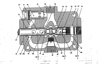
Referring first to Figure 1 of ths drawin0s, the valve illustrated comprises a
. va!ve body 42 with a high pressure fluid supply inlat 46 adapted to receive high
pressure fluid ~rom a suitable supply source. The body 42 also has a fluid discharge
. outlat 45 adapted, when appropriately connac~ed, to r~turn fluid to a suitable reservoir.
3 0 A distribution spool 71 is provided in a central bore 72 extending through the body 42
and is mounted to enable ro~ational movement within 1he bore and axia1 rnovement along
.; the longitudinal axis of lhe bore by~external rperator manipulation. Both ends of the
. . va!ve construction are sealed by appropria~e seal means sur:h as "O" rings 73. ~ One end of
~ the spool 24 p!otrudes through the valve body 42 for optional hand controls shown in
3~ Figures 9 and 10 enabling e%ternal operator manipulation. The hand controls shown i
Figures 9 and 10 and VaiVQ explanation shown in Figures 1 to 8 are described
hereinafter.
The valve body includes a plurality of pressure fluid delivery connections
suitably arranged around its outer surfaee, each 9f which communicate through the valve
5 bociy 42 to the csntral bore 72 via passage msans. In the illustrated ombodiment there
are proviried pairs of pr0ssure fluid delivery conn~ctions 1/2, 3/4, 516 and offset
pressure portals 30/31, 32t33 and 34/35 in matching pairs adapted to deliver andreceive hydraulic fluid from either end of double acting hydraulic cylinders sr the like.
Referring first io Figure 1, tha valv~ construction is shown with the valve spool
10 71 in a part cut away view, in a neutral operation position. In this position, hydraulic
fluid suppiied under pressure from a suitable source (such as a pump) to a fluid inlet
connection 46 passes through the valve construction to fluid outlet connsction 45 thereby
enabling return of the fluid to a suitable reservoir. The inlet connection 46, with the
valve in the neutral position, directs the fluid to a pair of HP ohambers 9a and 9b, that
15 extend both axially along the surface and around the circumferance of the distribution
spool 7~ and longitudinally adjacent to one another on either side of a circumferential
land 10 formed on the spool 71~ Four circumferentially spased control vents 13 are
positioned around the spool surface 71 leading into the respective chambers 9a and 9b at
the ends thereof distant from the land 10. The control vents 13 enable progressive flow
2 0 controi into and from chambers 9a and 9b.
-~ The land 10,' in the illustrated neutrai position, is.centrally located within the
low pressure (LP) chamber 25 located in the valve body 42 opening onto the bore 72 and
posttioned cantrally ~etween the channels 9a and ~b. The central LP chamber 25 leads
fluid to a closed centrs portal 44, and closed c~ntre outlet 11 ~not shown) then outward
2 5 to LP manifold ~Q and the outlet conn2ction 45. As a result, pressurised fluid entering
- : - the valve body.42 at inlet connection 46 passes via chambers 9a and '9b`ahd 25 to the
portal -44,- manifold ~0 and the outlet connection 45. Thus'in the neutral posi1ion, no
pressurised fluid is delivered ts any end user such as lift oylinders or ~he like.~ ~'
Figure 2 -also 'represents the valve construction in a' neu~ral posiiion but is a
3 0 section view taken on an opposite plane to that of Figure 1. Figure 2 illustrates a group
::. of.four.substantially;sguare or:rectangular passages~-1ga'and 19b and 14à and 14b
. ~ extending radially into the spool 71 from ils outer ~urface The two :'passages 19a and
- 19b being diametri~ally opposed reiative to'one another`and located on'one side of ~he
: central chamber 9a lead to a blind intsrnal bore 74 and the ~wo passagès 14a and 14b
3 5 lead to a second internal blind bore 75 within the spool 71 bul the bore 75 extends io the
- -
` ` `: ~' . : - ' ,
: ,, - : :
' '' " ' ~ '
'
2~97~33
opposite end of the spool 71 to that of bore 74. In Ihe bore 74, a non-return ball valve
seat 17 is provided. The ball valve 12 permits pressurised fluid flow outwardly along
the bore 74 frorn the passagaways 9a and 9b but not in a reverse direction. Similarly, i
the bore 75, a non-return valve 22 is provided spring-loaded inwardly by a second
5 spring 16b. Again the valve 22 permits pressurised fluid flow outwardly along the bore
7i5 from the passageways 14a and 14b but not in the reverse diraction.
In the spool 71, outwardly beyond the non-r~turn valve 12, there is provided twopassages 18a and 18b leading radially from the bore 74 to an outer surface of ~he spool
71. Similarly, from ~he circumferentially spaced passa~es 15a and 15b lead radially
10 from the bore 75 outwardly of the non-return valve 2Z to an outer surface of ~he spool
71. The passages 18a iand 18b and 1~a and 19b and 14a and 14b and 15a and 15b are
conveniently substantially square or rectangular when viewed circumferentially and are
restricted to a positive square area on the spool's outer surface. Whilst in the neutral
position (Figures 1 and 2), the passages 18a - to -15b are sealed from ieakiage against
15 solid wall sections of the central bore 72.
Arranged be~ween each of the passages 14a and ~b and 15a and 15b, are situated
a series of user delivery vents 76 and offset porting vents 76 as illustrated in cut away
view of shaft (Figure 1) showing vents 76 within valv~ cylinder (refer also Figures 5, 6
and 7). In Figures 5 and 6, the user delivery vents ars 1, 3 and 5 and in Figure 7, the
20 user delivery vents are 2, 4 and 6. The remaining connections 31, 33 and 3i5 (in
Figures 5 and 6) and 30, 32 and 34 (in Figure 73 being offset porting vents designed to
balance pressure on effective spool sllrface area and cut out ~hydraulic lockn. In each
casie an oMset porting Yent is diametrically opposed to one of 1he user delivery vents.
These vents are preferably shaped, at least at the point of exi2 and/or entry, in ia round
2 5 cross-s2csion area so as to allow tha sel~otion of more than one pair of users and offset
porting venls with a progressive control. ~
The user ~lents and the offset porting vents are conn0cted via passageways (refer
Figures i~ and 6~ to a transfer manifold 43 (refer Figure 8) ohannel 52 to 53 connecting
passageways 38 and 36. Correspondingly channel iS7 to 56 and 52 to 54 corirlecting 37 to
3 0 40 and 39 to 41. Accotdingly Figure 7 passageways also being connected by a similàr
o Now, with 2he spool-71 in ~he neutral position as shown in Figure 2, ànd if the
spool is moved axially to ihe right as shown in Figure 3, tha open faces of passages 18a
and 18b are brought into iine with Zhe delivery vent 1 and the offset porting vent 31.
:~ ~ ? ?' " '` ~ 9 ~ .~J'J~
-i . 3
At the same time, passages 1 ga and 19b also move into a position to conrJect with
the HP manifold 9a ~ed with pressurised fluid from inlet 46 (refer Figure 1).
Simultaneously, the passages 14a and 14b move to connect user vent 2 and offset vent 30
whils~ passages 15a and 15b connect tlle bore 75 to the LP manifold 27. Control vents
5 and the conlrol lands or bridge 1û progressively olos0 at a similar time to seal the LP
chamber 25 by co-operation with land 11, of the cylinder bore 72. In this
configuration, passages 1 8a and 18b and 19a and 1 9b bao~me Hp passages, and passages
1 4a and 1 ~b and 1 ~a and 15b become LP passages
If the spool 71 is moved to the left as shown in Fi~ure 4, the chambers 25 and 9b
1 û are progressively clssed by the spool sur~ace in relation to the cylinder bore. Passages
1 8a and 1 8b and 1 9a and 1 9b thereby become LP passages ~refer Figures 2 and 4). This
action in turn redirects oii through passages 14a and 14b by forcing non-return valve
22 from its seat into an opan position within passa~e 75. Thus pr~ssurised fluid is
allowed to flow in that direction throu~h HP outlets 15a and 15b. As a result, with the
15 spoot as shown in Figure 3, pressurised fluid is supplied to one end of a hydraulic lift
cylinder tor the like~ via a selected port and offsat port 1 and 31 respectiYely from the
inlet supply 46 (refer Fi~ure 1). As the same fluid is exhausted to the l~w pr~ssure
manifold 27 from the opposite end of the lif~ cylinder via passages 14a and i4b
connecting port 2 and offset port 30 (Figure 3) by forcing non-re~urn valve ~2 from its
2 0 seat to an open position. This exhausted fluid may return through bore 75 and passages
15a and 15b to the LP manifold 27. Il witl then be appreciatad that movement of the
spool to the right or left as described previously would provide a progressive connection
to the inlet 46, thereby providing a oontrol ovsr tha rate of pressurised fluid flow and
the rate of actuation of a lift cylinder connected thereto. The non-return valves 12 and
25 22 sifuated within cylinder spool 71, prevent high pressure feed-back during this stage
operation. The larger black arrows in the drawings denoling-oil flow direction.
~ Figures 9a, 9b, gc and 10 of the accompanying drawings illustrate an appropriate
rnechanisnn !or permitting an operator tc mov~ the distribution spool 71 both axially and
rotationally ~as desired. ~ J~
3 0 ~ An operating lever 59 mounted within a rotatable marnber 63 by a pin 67 and in
turn held within a body 61 and retained by a pin 64. One and of the operating lever 59
;i,; being for, manua! cortrol, the other enci slidably mounted within member 63 over pin 67
The rotatable member 63 is re~ained in the body 61 and is furth0r slidably connected by
. . .. .. .. . . . .
a pin and boss 66 to member 69. Mernber 69 is connected to spool 71. In this manner by
35 pivoting the lever 59 and member 61 about the pivot point 64, member 63 will be
:.
.
7 ~ 7 ~ ~ 3
moved axially ~hereby causing movement of the spool 71 in an axial direction within the
main bore 72. In addition, the operating lever 59 may also be rotated about axis 80
which also causes pin 66 to rotate about the axis of spool 71 thereby resulting in angular
movement o~ ~he spool to desired positions. The ball 65 is adopted to positively engage in
5 circumferential locations (recesses) upon rotation of the body 61 for the operator to feel
where the desired angular positions of the spool 71 are located. The link 62 may be
depressed by axial movement of the outer part of the lever 59 against biasing means to
release the oblique end of the lever 62 from a position locking the ball 65 at the desired
positions.
It will be apparent from the drawings that having returned the spool 71 to a
neutral position frorn the positions illustrated in Figures 4 and 3, movement of the spool
71 in a rotational direction to the left will position the spool 71 to a position such as that
iliustrated in Figure 2 with passages 18a and 18b and 19a and 19b, 14a and 14b and 15a
and 15b in axial alignment with supply outlets 1 and 2 and offset ports 31 and 30.
1 5 Operation to the right of this position passages 18a and 18b and 19a and 19b will connect
the supply ou~let 2 and offset port 30 to a source of pressurised fluid whilst passages 14a
and 14b and 15a and 15b connect supply outlet 1 to exhaust manifold 50 via passage 20.
It will further be appreciated ~hat similar controi movement~ to those described above
are possible for aach of the supply outlet port pairs 1 and 2, 3 and 4 and 5 and 6 also
20 offset porls 30 and 31, 32 and 33 and 34 and 35 respectivsly and individually with the
spool 71 in selectQd rotational positions as defined by operation. In addition to the
foregoing, it is possible to connect at l~ast two pairs of supply outlets tv the pressurised
fluid supply ~6 simuHaneously by selectively rotating the spool part way batween the
positions previously identified.
In this manner, as shown in Figure 6, it is possible for the pressure outlet
passages to contact separate adjacent pairs of supply outlets 1 and 2 and 5 and 6 also
offset ports 31 and 30 and 35 and 34 as iilustrated ~refer Figures 9a, 9b and 9c). It is
apparent that the adjac~nt outlst 3 and 4 to 1 and 2 and 5 and 6 to 3 and 4 withcompatible offset ports ara capable of simultaneous operation in the same manner.
3 0 Ther~fore enabling the valve to operate either as 1 valve function, 2 valve function, 3
valve function or as a complete mixing vaJve by selectively operating any 2 valve
functlons In a slmultaneous manner. Figure 9a showlng a lever mechanism relaining
valve In line with user vents 1 and 2 held In place by ball 65 and lever 62 while in
Figure gb ~he valve Is retained in line with user vents 5 and 6. Figure 9c shows the
3 5 valve mixing user vents 5 and 6 with user vents 3 and 4. It is highly desirable that the
r '!. ' `~
respective ports at the interface of spool 71 and the supply outlats be round inconfiguration in the cylinder bore and substantially square or rectangular in
configuration within the spool. As without this configuration thsre could be insufficient
open area provided when the valve is operated for use in simultaneous manner. Finally it
5 will be apparent 7rom Figure 1 of the drawings that the housing ~an be machined and
fittad with a selactabla pressure r01iaf valve 48 connecting LP axhaust manifold 47, 50
to I JP manifold 49 allowin~ any HP build up during operation to be channalled back to lhe
supply reservoir. The valve 48 is retained in a longitudinal neutral position asillustrated by a typical valve spring (not shown in the accompanying drawings).
1 0
- . ~
:: . . : , ;
.. . . .. . .... ..
.. . ,: .
.