Note: Descriptions are shown in the official language in which they were submitted.
2098~9~
1
ELECTRONIC IDENTIFICATION SYSTEM HAVING REMOTE
AUTOMATIC RESPONSE CAPABILITY AND AUTOMATIC
IDENTIFICATION METHOD THEREOF
S
TECHNICAL FIELD
The present invention relates to an electronic identification system having
remote
automatic response capability and an identification method thereof, and more
particularly,
to an electronic identification system having remote automatic response
capability and an
identification method thereof in which an identification control apparatus
remotely calls
and responds to a portable electronic apparatus to perform self-identification
between the
identification control apparatus and the portable electronic apparatus and to
thereby
automatically control a piece of equipment to be controlled, so as to be
widely used with
any individual identification apparatus and to have an excellent security
feature.
BACKGROUND ART
Recently, along with developments in electronics technology, electronic
identification apparatuses for personal use have been rapidly developed. A
personal
identification apparatus is conventionally applied to a wide range of fields,
including
doors, vehicular starters, personal computers and safes, as well as for use
with prepaid
card systems such as public telephones, parking lots and highway toll gates.
The fields
of application are continuously expanding at an increased rate.
Various types of the conventional individual identification apparatus can be
classified according to the inputting method of their identitication (ID)
codes, i.e., push-
button, card-insertion, fingerprint ID, speech-recognition, etc. Among these,
the push-
button type has been most widely used, in which a user memorizes a secret
access
number and inputs the number into a system by pressing keys. This method has
recently
developed further, in connection with a wireless method. On the other hand,
the card-
insertion type utilizes a magnetic strip card, a punched card or an electronic
card
containing an integrated circuit (called an "IC card"), which is inserted into
a card reader
as the method for ID code input. In current systems however, the magnetic
strip card
system has been supplanted by that using IC cards, and accordingly, a mufti-
functional
IC card system is being pursued. (Though fingerprint ID and speech-recognition
type
systems have been recently introduced, they have certain problems in view of
the real-
2~°8~9~
2
time processing of fingerprints and speech, as well as low reliability and an
impractical
cost to the consumer, so wide distribution of these has not yet been made
possible.)
With the conventional push-button system, the user need only to memorize an
access number and does not run the risk of losing a key, card, etc. However,
with
increasing incorporation of more identification systems, more ID numbers
become
necessary, and thus users are burdened with learning numerous access numbers.
Also,
operating the identification apparatus requires the cumbersome pressing of
buttons to
input the access code. Moreover, since the keypad is apt to be in sight of a
third party
when operating the buttons, an inherent fallacy exists in view of security and
safety.
In the conventional card-insertion system, memorization of the access number
is
unnecessary. However, as with the push-button system, every time the
identification
apparatus is to be operated, the card must be inserted into the card reader,
and if the user
misplaces the card, unauthorized third-party usage is impossible to prevent.
Accordingly,
here too is an inherent fallacy, resulting in lowered security and safety. As
for the IC
card system, the issuance of the IC card itself is difficult because issued
cards should be
monitored, so its usage has been limited.
In each case other than the speech recognition system, the above-described
conventional identification apparatus systems require manual manipulation by
the user for
operation, and thus when both hands are busy, a user is incapable of inputting
the
necessary information. Also, the conventional systems are specified according
to the field
of use and the entry method, so that their widespread usage is limited, i.e.,
in the home,
at the office, outdoors, on the road, etc. Additionally. an integration-
control method of
all these identification systems is impossible in certain geographical areas.
Now, as
current trends in self-service automation (vending machines, automatic toll
booths, self
service sales counters and parking lots, etc.) are proceeding at an
accelerated rate in the
every field of industry and home life, the necessity for an integrated
identification system
is becoming increasingly obvious.
DISCLOSURE OF THE INVENTION
Therefore, to solve the above problems, it is an object of the present
invention to
provide an electronic identification system having remote automatic response
capability
for which a master key method is applied so as to be capable of integrated
control of
various types of individual identification apparatuses.
2~98~9~
3
It is another object of the present invention to provide an electronic
identification
system having remote automatic response capability in which both of a user's
hands are
free, even when identification is carried out, by way of a remote automatic
response.
It is still another ob;ect of the present invention to provide an electronic
identification system having remote automatic response capability in which
labor costs
can be saved by facilitating the system's registration and administration
procedures.
It is yet another object of the present invention to provide an electronic
identification system having remote automatic response capability in which
security and
safety are very high.
It is yet still another object of the present invention to provide an
electronic
identification system having remote automatic response capability in which the
system
discriminately operates according to various levels of user access.
It is a further object of the present invention to provide an electronic
identification
system having remote automatic response capability for controlling the status
of passage.
It is still a further object of the present invention to provide an electronic
identification system having remote automatic response capability to which a
pre-paying
method can be adapted.
It is yet a further object of the present invention to provide an electronic
identification system having remote automatic response capability in which a
paid
attendance can be automatically controlled.
It is still yet a further object of the present invention to provide an
electronic
identification system having remote automatic response capability for use in
automatically
controlling a toll gate.
It is still another object of the present invention to provide an electronic
identification system having remote automatic response capability for use in
connection
with automatic bank deposit and withdrawal transactions.
To accomplish the above objects of the present invention, there is provided an
electronic identification system having remote automatic response capability,
comprising:
at least one portable electronic apparatus enabled by a user's password input,
which, if
a specific code loaded on a received call signal matches one of a plurality of
specific
codes registered in a first memory, loads a user access code corresponding to
the matched
specific code onto an identification signal and transmits the access-code-
loaded
identification signal; and at least one automatic identification control
apparatus which, if
~09~094
4
access of a user in possession of the portable electronic apparatus is
detected, transmits
the specific-code-loaded call signal and receives the user-access-code-loaded
identification
signal which is generated in response to the call signal, and which, if the
user access
code loaded on the identification signal matches one of a plurality of user
access codes
registered in a second memory, then operates a piece of equipment to be
controlled,
thereby resulting in that the automatic identification control apparatus
having a plurality
of registered specific codes, one of which corresponds to the enabled portable
electronic
apparatus, performs a call and identification operation according to access
requests of the
portable-electronic-apparatus-possessing user.
Here, the portable electronic apparatus comprises memory means for storing
specific codes assigned to at least one automatic identification apparatus, a
user access
code and password, a receiver for receiving a wireless call signal, a
transmitter for
transmitting a wireless identification signal, and control means for
generating the
identification signal based on the user access code and password, if a
specific code
received in response to the call signal matches one of a plurality of specific
codes
registered in the memory means.
The automatic identification apparatus comprises memory means for storing user
access codes assigned to at least one portable electronic apparatus, specific
codes and a
user's password, a detector for detecting the approach of a mobile object in
possession
of a portable electronic apparatus, a transmitter for transmittin g a wireless
call signal, a
receiver for receiving a wireless identification signal, and control means for
generating
the call signal based on the specific code in response to the detection
signal, and for
generating a control signal if a user access code received in response to the
identification
signal matches one of a plurality of user access codes registered in the
memory means.
Thus, using the system of the present invention, if the mobile object having
the
portable electronic apparatus is accessed to the automatic identification
apparatus, since
an automatic identification operation is performed by the automatic
identification
apparatus which mutually responds with the portable electronic apparatus, both
hands of
the user are free.
The system of the present invention can embody a prepaying system by storing
data corresponding to an amount of prepaid money into the memory means of the
portable electronic apparatus, subtracting cost data calculated and
transmitted by the
automatic identification apparatus from the stored data, and updating that
data with the
2~98~9~
subtracted result which becomes the new amount of prepaid money. Thus, all the
identification systems can be integrated, and controlled with a single
portable electronic
apparatus. That is, the user's secret access codes are registered in his
household's
electronic opening and closing apparatus, the start-up devices of va~:oas
electronic
5 products (e.g., personal computer, etc.), the door locks of his vehicle, fee-
levying Control
apparatuses adapted to toll gates for highways, bridges, tunnels, etc.,
parking lots, and
the paid attendance control apparatuses of cafeterias, movie theaters, etc.
Here, individual
fees and the specific codes of the corresponding automatic identification
control
apparatuses are registered in the portable electronic apparatus, enabling
fully integrated
application. Also, the system of the present invention simultaneously makes
inquiries as
to the credit status of the user, and if the control apparatus is connected
with a bank's on-
line computer or that of a credit card company, automatic cash and credit
purchases and
an automated bank deposit-and-withdrawal transaction system are thus enabled.
There is also provided an automatic identification control method for an
electronic
identification system having remote automatic response capability comprising
the steps
of: (1) transmitting a call signal on which a specific code is loaded in
response to an
initial enable signal; (2) transmitting an identification signal on which a
user access code
corresponding to the specific code is loaded, if the specific code detected
via the call
signal matches one of a previously registered, plurality of first specific
codes; (3)
determining whether a user access code detected via the identification signal
matches one
of a previously registered, plurality of second specific codes; and (4)
transmitting and
receiving an instruction and data, after mutual identification by way of steps
(1), (2) and
(3).
BRIEF DESCRIPTION OF THE DRAWINGS
FIG.I is a block diagram of an electronic identification system having remote
automatic response capability according to the present invention.
FIG.2A through 2E are views showing various embodiments of the portable
electronic apparatus shown in FIG.I.
FIGs.3A and 3B are diagrams for explaining signal formats of call and
identification signals used in connection with FIG.1.
FIG.4 is a diagram showing a key matrix of the input means of FIG.l.
FIGS is a view showing a memory map for a storage means in the portable
209594
6
electronic apparatus of FIG.I.
FIG.6 is a view showing a memory map for a storage means in the automatic
identification control apparatus of FIG.1.
FIG.7 is a flowchart diagram for explaining the mutual registration procedure
of
the system according to the present invention.
FIG.8 is a block diagram of one embodiment of the portable electronic
apparatus
of FIG.1.
FIG.9 is a block diagram of one embodiment of the automatic identification
door
opening/closing device according to FIG.1.
FIG.10 is a circuit diagram of the transmitter/receiver shown in FIGs.8 and 9.
FIG.11 is a view for explaining the detector of FIG.9.
FIG.12 is a flowchart diagram for explaining a control program for FIG.B.
FIG.13 is a flowchart diagram for explaining a control program for FIG.9.
FIG.14 is an operational mode diagram for explaining a mutual communication
procedure between a number of the automatic identification door
opening/closing devices
6
and a portable electronic apparatus.
FIG.15 is a view for explaining a passage restriction relationship according
to
access level assignment, which is applied to the automatic identification door
opening/closing device of the present invention.
FIG.16 is a block diagram of the automatic identification door opening/closing
device having a passage control function of the present invention.
FIG.17 is a view showing an example of the attendance record table output from
the printer of FIG.16.
F1G.18 is a view for explaining an attendance control system being one
embodiment of the present invention.
FIGs.I9A and 19B are a perspective view and a block diagram of the cash
registering device being one embodiment of the present invention.
FIG.20 is a flowchart diagram for explaining the cash-registering procedure of
FIGs.I9A and 19B.
FIG.21 is a flowchart diagram for explaining the prepaid fee-levying procedure
being another embodiment of the present invention.
FIG.22 is a view for explaining the toll gate fee-levying system being still
another
embodiment of the present invention.
209~~9~~
7
FIG.23 is a flowchart diagram for explaining a mutual communication
relationship
between an automatic identification control apparatus and the portable
electronic
apparatus of FIG.22, for entering.
FIG.24 is a flowchart diagram for explaining a mutual communication
relationship
between an automatic identification levying control apparatus and the portable
electronic
apparatus of FIG.22, for exiting.
FIG.25 is a view for explaining the automatic identification credit
transaction
system being yet still another embodiment of the present invention.
FIG.26 is a flowchart diagram for explaining a mutual communication
relationship
between the automatic identification credit transaction system and the
portable electaronic
apparatus of FIG.25.
FIGs.27A and 27B are a perspective view and a block diagram of the automatic
banking system being still yet a further embodiment of the present invention.
FIG.28 is a flowchart diagram for explaining the operation of the automatic
banking system of FIGs.27A and 27B.
FIGs.29A through 29F are diagrams which show various display states of the
CRT of FIGs.27A and 27B.
BEST MODE FOR CARRYING OUT THE INVENTION
The preferred embodiments of the present invention will be described below in
more detail with reference to the accompanying drawings.
FIG.1 is a block diagram of an electronic identitication system having remote
automatic response capability according to the present invention. In FIG.I, a
portable
electronic apparatus 100 comprises input means 110, control means 120, storage
means
130, receiving means 140, transmitting means I SO and display means 160.
Automatic
identification control apparatus 200 comprises input means 210, control means
220,
enable means 230, transmitting means 250, receiving means 260, drive means
270,
operation detecting means 280 and alarm means 290.
Input means 110 of portable electronic apparatus 100 comprises a key matrix
circuit for performing user password and mode selection, and power-on and
power-off
functions.
Control means 120 comprises a microcomputer, a control program ROM, a
SRAM and DRAM for data storage, a clock generator circuit and a piezoelectric
device
~098~~~
s
for generating an audible alarm signal.
Storage device 130 comprises a non-volatile memory, that is, a EEPROM for
storing the user's password and access code, specific codes pertaining to the
particular
automatic identification control apparatus' registration, and other data.
Receiving means 140 comprises a radio demodulation circuit or a light-
receiving
circuit for receiving a modulated RF or IR call signal, and detecting the
specific codes
and data loaded on the call signal, which are transmitted from the automatic
identification
control apparatus.
Transmitting means 150 comprises a radio modulation circuit or a light-
modulating
circuit for modulating the user's access code and specific data, and
transmitting an
identification signal.
Display means 160 comprises a display device (LCD, LED, etc.) and the LCD
or LED driver, for displaying data according to the key operation of input
means 110,
and data or an operating state according to the processing results of control
means 120.
Portable electronic apparatus 100 may comprise an IC card interface circuit
for
bi-directionally communicating with the existing IC card, and may also
comprise an input
and output interface circuit for bi-directional communication with a personal
computer.
Here, portable electronic apparatus 100 further comprises a primary or
secondary battery
cell and a power supply check circuit therefor; these however are not shown in
FIG.1.
Portable electronic apparatus 100 may be in the. form of a ball-point pen
(FIG.2A)
for convenient carrying, a business-card-sized card (FIG.2B), a wristwatch
(FIG.2C), a
jewelry item, e.g., pendant (FIG.2D), stickpin or broach. or a belt buckle
(FIG.2E). To
facilitate miniaturization of such a portable electronic apparatus, that is,
in the case of the
ball-point pen, necklace or belt buckle, only tour input keys are necessary.
Here, when
an UP (U or T ) or DOWN (D or ~ ) key are pressed, an LCD panel scrolls
through
figures and/or characters, and a set key is pressed when the desired display
appears, thus
selecting an input. (If wrongly set, a cancel key is pressed.) When all the
desired data
has been input, a registration key is pressed, to thereby lock-in the
displayed input data
for transmission to the internal control means.
As shown in FIG.2B, portable electronic apparatus 100 can have a function
select
switch for various modes: electronic calculator (CAL), clock (OFF) and
identification
(ID). Also possible but not depicted, portable electronic apparatus 100 may be
connected
with a beeper, cellular phone or miniature FM receiver.
209~~9~
9
Input means 210 of automatic identification control apparatus 200 comprises a
key
matrix circuit having digit keys and various mode keys.
Control means 220 comprises a microcomputer, a control program ROM, an
SRAM and DRAM for data storage, a clock generator circuit and a piezoelectric
devic;,.
Detection means 230 comprises a detecting circuit having a proximity sensor
such
as an infrared light sensor or a supersonic wave sensor for detecting the
approach of a
mobile object carrying portable electronic apparatus 100, for example, a human
being or
automobile.
Storage means 240 comprises a non-volatile memory, that is, an EEPROM for
storing the administrator's password and specific codes, user registration
codes, and other
data.
' Transmitting means 250 comprises a radio modulation circuit or a light-
modulating
circuit for modulating a specific code and data, and transmitting the
modulated signal as
a call signal.
Receiving means 260 comprises a radio demodulation circuit or a light-
receiving
circuit for receiving a modulated RF or IR identification signal, and
detecting the user's
access code and specific data.
Driver means 270 comprises a driver circuit for driving the equipment to be
operated in response to a control signal which is generated when user access
codes are
received by control means 220 and match a registered user's code.
Operation detection means 280 is connected with driver meant 270 or directly
to
the equipment to be operated, and comprises an operation detection circuit for
detecting
the operating state of the driven or operated equipment.
Alarm means 290 comprises an alarm generating circuit and a misoperation
indicating circuit for generating an audible and/or visible alarm to signal
the improper
operation of the equipment to be operated or the access of an unregistered
(unauthorized)
mobile object.
Automatic identification control apparatus 200 is connected with predetermined
equipment to be operated according to installation locations. For example, for
installation
at a main entrance, automatic identification control apparatus 200 is linked
with an
opening and closing mechanism and an intercom, and for use with an electronic
product,
say, a computer, it is tied to a lock-out or start-up device. Further, if
automatic
identification control apparatus 200 is to be used in conjunction with a paid
attendance
209894
to
control system (cafeteria, movie theater, etc.), it may be interfaced with a
turnstile. Other
interconnection examples include that for toll gate systems, e.g., toll roads,
tunnels,
bridges, etc.
Automatic identification control apparatus 200 can also be connected with a
camcorder, to photograph vehicles and their passengers.
Also, automatic identification control apparatus 200 comprises a display means
(e.g., LCD, LED, etc.) to display data and operation state, or comprises an
I/O interface
means to enable bi-directional communication with a computer. Also, to
miniaturize the
portable electzonic apparatus according to the present invention, the input
means of the
portable electronic apparatus can be omitted. Instead, the necessary
information can be
input via the input means of the automatic identification apparatus, to then
write the
necessary information to the portable electron is apparatus via the
transmitting and
receiving means.
FIGs.3A and 3B show the structures of a call signal CAS and an identification
signal IDS, respectively. Call signal CAS is a signal obtained from the
modulation (RF
or IR) of start signal ST, a specific code XC, user secret code USC, data DT,
and an
end-of data signal ED. Similarly, identification signal IDS is a signal
obtained from the
modulation (RF or IR) of start signal ST, user secret code USC, address ADD,
data DT,
and an end-of-data signal ED. Here, the CAS and IDS signals may be encoded and
error-
correction-encoded during transmission, and decoded and error-correction-
decoded during
reception, via well-known methods.
In RF-transmitting and RF-receiving the above call and identification signals,
a
subcarrier frequency on the order of hundreds of megahertz is used, in
consideration of
the miniaturization of portable electronic apparatus 100. For this purpose,
internal
transmission and reception loop antennas are desirable and formed of copper
film on
printed circuit board. When these signals are communicated via light
transmitting and
receiving apparatuses, a light modulation method for 'driving a light-emitting
device can
be used, in which the switching of a 40-50KHz oscillator is performed
according to a
data train.
The registration procedure of the specific codes and the user's secret access
code
(USC) adapted in the electronic identification system having remote automatic
response
capability according to the present invention as described above will be
described below
with reference to FIGs.4 through 7.
209~:i9~
1i
As shown in FIG.7, a user possessing portable electronic apparatus 100 of the
present invention inputs a manufacturer- or dealer-determined initial user
password IUPW
through input means 110 having key input means shown in FIG.4 or FIGs.2A-2E.
Then,
control means 120 of portable elecrronic apparatus 100 compares the input IUPW
data
with the previously stored IUPW data in a memory region of storage means 130
shown
in FIGS, and if they match, an "enable" indication appears on display means
160. The
user then inputs his own personal password UPW data through input means 110.
Subsequently, when an "UPDATE" key is pressed, control means 120 deletes the
IUPW
data stored in a first memory region 131 of storage means 130 and writes the
UPW data
therein. When the user inputs his personal identification UPC data (e.g., ID
number,
vehicle number, bank account number, health card number, etc.), and then
presses a
"REGISTRATION" key, control means 120 sequentially writes the user's UPC data
in
a second memory region 132 of storage means 130. Here, the user can cancel the
input
data by pressing a "CANCEL" key prior to pressing the "UPDATE" or
"REGISTRATION" keys during the UPW-updating or UPC-writing procedure.
On the other hand, also shown in FIG.7, in a similar method to that of
portable
electronic apparatus 100, the system administrator, being in possession of
automatic
identification control apparatus 200 of the present invention, inputs the
administrator's
password data APW and specific code data XC using an initial administrator's
password
IAPW, in a first memory region 241 and a second memory region 242 of storage
means
240, as shown in FIG.6. If the user presents portable electronic apparatus 100
to the
administrator after inputting his password, i.e.. enabled, and intorms the
administrator
of the necessary UPC data, the administrator inputs XC data identical to that
written in
automatic identification control apparatus 200 through input means 110, and
presses a
"REGISTRATION" key. Then, control means 120 of portable electronic apparatus
100
writes the input specific code data XC, in an address UPPP of a third memory
region 133
in storage means 130. Also, the administrator inputs the user-supplied UPC
data through
input means 210 of automatic identification control apparatus 200, and presses
the
"REGISTRATION" key. Then, control means 220 of automatic identification
control
apparatus 200 writes the input personal identification data UPC, in an address
MGGG of
a third memory region 243 in storage means 240. After completion of the above
operation, and the administrator has returned the XC-data-written portable
electronic
apparatus 100, the user presses the "REGISTRATION" key and sets a registration
mode.
2Q~s~9~~
12
Then, if the user takes a thus-set portable electronic apparatus 100 and
approaches
automatic identification control apparatus 200, the identification control
apparatus detects
the user's approach through detection means 230, and transmits a first call
signal CAS
through transmitting means 250. Control means 120 of portable electronic
apparatus 100
compares the detected XC data from first call signal CAS received through
receiving
means 140 with the written XC data. If the detected XC matches the written XC,
corresponding UPC data is read out from storage means 130, to be transmitted
with a
registration instruction signal RIS and the address data UPPP of XC, as a
first
identification signal IDS via transmitting means 150. Control means 220 of
automatic
identification control apparatus 200 compares the detected UPC data from first
identification signal IDS received through receiving means 260 with the
written UPC
data. If the detected UPC matches the written UPC, the registration
instruction signal
(RIS) is decoded, and the received UPPP data is written in an address MFFF of
third
memory region 243 in storage means 240 in connection with address MGGG where
the
UPC data is stored. By doing so, the user's secret code USC is registered,
thereby
transmitting the XC, UPPP and MFFF data as second call signal CAS via
transmitting
means 250. Control means 120 of portable electronic apparatus 100 reads out.
the XG~
data located in address UPPP of storage means 130, using the UPPP data
detected from
second call signal CAS received through receiving means 140. Here, if the read
XC,
matches the received XC, the received MFFF data is written as the user's
secret access
code USC, in address UPPP + XXX of a fourth memory region 134 of storage means
130. Accordingly, registration of a user's secret code USC (access code) and
his specific
code XC is accomplished. Then, a second identification signal, that is, IDS =
UPPP +
MFFF + reception confirmation signal (ACK), is transmitted through
transmitting means
150 and the program terminates. Automatic identification control apparatus 200
receives
the second identification signal and cont~rms if the registration procedure is
accomplished, which also terminates the program.
As described above, in the present invention, portable electronic apparatus
100
is mutually communicated with automatic identification apparatus 200, and in
so doing,
registration of both the final specific code (XC) and the user's secret access
code (USC)
is performed. Therefore, a user cannot recognize specific codes of the control
apparatus,
nor can an administrator recognize the secret user-access codes. Thus, fraud
on the part
of the user or the administrator can be prevented to guarantee security and
safety.
2~9~~9~
13
Also, the corresponding memory region is directly addressed by the received
address information, without the need for searching specific codes or user
access codes,
due to registration of both the portable electronic apparatus numbers and the
automatic
identification control apparatus numbers. Accordingly, real-time processing
can be
performed without slowing the memory access time.
Operation of the present invention in which the specific code and the user's
secret
access code are registered as described above, will be described below by way
of various
embodiments.
DOOR LOCK SYSTEM
Referring to FIG.B, one embodiment of portable master key 100 according to the
present invention comprises: input means I 10 having key ~;.utrix 110a' and
interface
circuit 110b; control means 120 composed of a microcomputer; storage means 130
composed of a non-volatile memory such as a EEPROM; receiving means 140 having
a
high frequency amplifier 141, a local oscillator 142, a frequency converter
143, an FM
discriminator and filter portion 144, and an inverting amplifier 145;
transmitting means
150 having a high frequency oscillator 151, an oscillator I52, an FM modulator
153 and
an intermediate frequency amplifier I54; and display means 160 having a liquid
crystal
display 160a and an interface circuit 160b.
Receiving and transmitting means 140 and 150 comprise a serial-to-parallel
converter 140a for serially receiving the specific code data detected from the
call signal
which has been received and amplified and converting the serial data into
parallel data
to supply it to microcomputer 120, a parallel-to-serial converter 150a for
receiving in
parallel the user's secret code data and instruction data output from
microcomputer 120
and converting the parallel data into the serial data to supply it to
transmitting means 150,
and switching means 170 for performing a switching so that power supply
voltage Vec
of a battery cell is supplied to transmitting and receiving means 140 and 150
in response
to power supply control signal PW of microcomputer 120. The user's secret
code, the
user's password, and the specific code and the instruction code of the
automatic
identification door opening and closing device are stored in the EEPROM being
storage
means 130. Serial-to-parallel converter 140a and parallel-to-serial converter
150a may be
composed of one common serial-to-parallel converter in which the input and
output are
reversed and controlled according to the states of reception and transmission.
209~~9~
14
Transmitting and receiving means 140 and 150 may adopt a known FM-receiving
circuit
having a 300-900MHz subcarrier. Display means 160 displays the input state of
input
means 110 on an LCD panel or the operating state of the opening and closing
mechanism
performing transmission and reception response using the call signal and the
identification
signal.
Referring to FIG.9, one embodiment of automatic identification door
opening/closing device 200 according to the present invention comprises input
means 210
having a key matrix 210a and an interface circuit 210b; control means 220
composed of
a microcomputer which can function as a clock; detection means 230 having
first and
second external sensors 231 and 232 and first and second internal sensors 233
and 234
for sensing the approach of a mobile object; storage means 240 composed of a
non-
volatile memory such as a EEPROM; transmitting means 250 having a high
frequency
oscillator 251, an oscillator 252, an FM modulator 253, and an intermediate
frequency
amplifier 254 for transmitting a call signal; receiving means 260 having a
high frequency
amplifier 261, a local oscillator 262, a frequency converter 263, an FM
discriminator and
filter portion 264, and an inverting amplifier 265 for receiving the
instruction signal,
equipment to be operated 270 having an interface circuit 270a and an driver
circuit 270b;
and alarm means 290 having an alarm circuit and speaker.
The embodiment of automatic identitication door opening/closing device 200
according to the present invention also comprises a system enable switch 221,
a serial-to-
parallel converter 260a, a parallel-to-serial converter 2~Oa, and operation
detection means
280.
Detection means 230 detects the approach of a mobile object and supplies a
system
enable signal to microcomputer 220 which thereby generates a power supply
control
signal PW to turn on switch 221. Accordingly, power supply voltage Vcc is
supplied to
transmitting and receiving means 250 and 260. Transmitting and receiving means
250 and
260 are connected with microcomputer 220 through serial-to-parallel converters
250a and
260a.
Storage means 2f0 composed of the EEPROM stores the user access code of at
least one portable master key, the specific code, the administrator's
password, and data
establishing the in and out times of persons. Driver circuit 270b
conventionally drives a
solenoid and electronically controls the opening and closing operation for the
door. Also,
a motor driver circuit may be adapted as driver circuit 270b, for controlling
the opening
209s~9~
and closing of the door via a motor. Operation detection means 280 monitors
the opening
and closing state of the door to supply the detected state to microcomputer
220. Here,
a switching state detection circuit by which the switching of a solenoid is
sensed to
thereby detect an operating current,'voltage change in the solenoid, may be
used as the
5 operation detection means.
FIG.10 shows one embodiment of the FM transmitting and receiving circuit of
FIGs.8 and 9, which is well-known. Thus, explanation of its detailed
construction and
operation will be omitted.
FIG.11 shows one embodiment of detection means 230 adapted in the present
10 invention. First and second outer detection areas OA, and OAZ of first and
second
external sensors 231 and 232 for detecting the approach and presence of
persons wishing
to gain entry, as w;,ll as first and second inner detection areas IA, and IAZ
corresponding
to first and second internal sensors 233 and 234 for the likewise detection of
an exiting
person, are established as shown in the drawing. Thus, the approaching
subject, while
15 in possession of a portable master key, desires entry through the door, his
access status
is first detected by first external sensor 231 and then by second external
sensor 232,
thereby determining access status. First and second internal sensors 233 and
234 operate
similarly for exiting from the inner areas.
Operation of the present invention as described above will be described below
with reference to FIGS. l , 8 and 9.
First of all, the combination of a user's secret access code and a specific
code
supplied by the manufacturer or dealer is assigned to portable master key 100
and
automatic identification door opening/closinQ device 200. That is, both the
access code
of the bearer of portable master key 100 and the specific code of the door to
be accessed
2S are written in the portable master key, while respective user access codes
of all those
permitted access are written in automatic identification door opening/closing
device 200.
When the user inputs his password through input means 110, control means 120
compares the input password with the stored password and determines whether
they
match, if so, the system is enabled. (Thus, even if the portable master key is
lost, it is
useless unless the password is identified.) In a thus-enabled portable master
key,
switching means 170 is turned on to supply power to transmitting and receiving
means
140 and 150, so that signal transmission and reception is possible. Once
portable master
key 100 has been enabled, if the user wishes to gain access to the door, his
approach is
~a~~~.~~~
16
detected by first external sensor 231, which enables the system.
That is, microcomputer 220 turns switch 221 on, to supply the power to
transmitting and receiving means 250 and 260. Subsequently, the specific code
registered
in storage means 240 is read out, and the read parallel data is converted into
serial data
through parallel-to-serial converter 250a. The serial data is FM-modulated by
transmitting
means 250 and transmitted as the call signal. In portable master key 100, the
call signal
received through receiving means 140 is demodulated to detect the serial data.
The
detected serial data is converted into parallel data via serial-to-parallel
converter 140a.
Then, the converted parallel data is supplied to microcomputer 120. If a match
is found
between the input specific code and a stored specific code, microcomputer 120
reads out
the user access code and an "open door" instruction code and transmits them as
an
identification signal via parallel-to-serial converter 150a a~~d transmitting
means 150.
(Here, automatic identification door opening/closing device 200 compares the
user access
code input through receiving means 260 and serial-to-parallel converter 260a
with a
previously stored plurality of user access codes, and when a match is
determined, the
user is recognized as an authorized person for entry.) After the instruction
code is
decoded, driver circuit 270b is driven via interface circuit 270a in response
to the
received signal from second external sensor 232, to drive the necessary
mechanism to
operate the door (unshown). For example, for an "open door" instruction
signal, the
solenoid is operated to open the door, and the current time and user
identification
information are stored in storage means 240, using the internal clock of
microcomputer
220. Thereafter, as the user passes through the opened door and enters the
region of
second internal sensor 234, the door is closed. Operation detection means 280
verifies
the closing of the door, and if not completely closed, the alarm is generated
via alarm
means 290. Thus, after the user passes through the door, the presence or
absence of the
alarm tells the user whether the door closes. In such a situation, the user
can visually
and/or manually check for possible obstructions.
FIG.12 is a flowchart of a control program of one preferred embodiment of a
portable master key. Portable master key 100 is initialized when the initial
power is
applied (step 401). Then, the user's password and instruction are input via
input means
110 (step 402). Here, the user's password is set as a four-place figure, and
the instruction
is set by combination of the function and numeric keys. If the input password
matches
the stored password (step 403), the system is enabled to allow transmission
and reception
209~:~9~~
17
(step 404). Next, the instruction is decoded and the given mode is
discriminated (step
405). If the given mode is an updating mode, updating of the user's password
or the data
is performed (step 406). If the given mode is an identification mode, the user
access code
and the instruction code are read out (step 407) to transmit an identification
signal (step
408) and receive the call signal (step 409). Then, it is determined whether
the specific
code matches the stored specific code (step 410), and if so, the received data
is stored
(step 411). Next, it is checked to determine whether the received data is
complete (step
412), and if so, the received data is displayed via display means 160 (step
413). If the
given mode is an operational mode, the call signal is received (step 414).
Thereafter, the
received specific code is checked against the previously stored specific code
(step 415),
and if they match, the user access code and the door opening instruction code
is read out
(step 416), to transmit an identification signal (step 417). Thus, operation
of the system
is completed.
FIG.13 is a flowchart of one preferred embodiment of an automatic
identification
door opening/closing device. In FIG.13, the control program initializes the
system when
power is initially applied (step 501). Then, approach of a mobile object is
detected by the
first internal or external sensor (step 502), which enables the system, and in
turn enables
transmission and reception (step 503). Subsequently, the call signal on which
the specific
code is loaded is transmitted (step 504), followed by checking the reception
of the
identification signal (step 505). When no identification signal is received,
call signal
transmissions are counted (step 506), and if they exceed a predetermined
number, say,
five, without a response, the alarm signal is generated (step 507), ending the
program.
If a signal reception in response to the call signal is determined within the
predetermined
number of times, the identification signal is received (step 508). Then, it is
determined
whether the user access code loaded on the identification signal matches the
stored user
access code (step 509), and if they match, an authorized user is confirmed and
the
instruction is decoded. A mode is determined according to the decoded
instruction (step
511). If the mode is an updating mode, the recorded user access code is
updated,
becoming a new user access code (step 512). Here, the program terminates. If
the mode
is an identification mode, the access level data is read out (step S 13).
Subsequently, the
data is transmitted (step 514). It is then checked whether the data
transmission is
complete (step 515), and if so, the program may terminate here, too. If the
mode is an
operational mode, the door is unlocked (step 516), and completed passage is
verified
2098j9~
is
(step S 17). After elapse of a predetermined time (step 518), the door is
locked again (step
519). At this time, misoperation is determined, that is, whether the door is
completely
closed (step 520), and if not, the alarm signal is generated (step 521). When
normal
operation is verified, the current time and individual identif ration
information is recorded
(step 522), which also terminates the program.
Referring to FIG.14, a procedure of passing through a plurality of the door
lock
systems will be explained. In FIG.14, when the user inputs UPW data containing
access
level information to portable master key 100, and wishes to gain access to a
first
automatic identification control apparatus I corresponding to a first door,
detection means
230 of first automatic identification control apparatus I detects his approach
and transmits
the call signal. Portable master key 100 receives the call signal and compares
specific
code XC with specific code XC, regisicred in an address UPPP, and if a match
is
determined, the identification signal is transmitted. The automatic
identification control
apparatus receives I the identification signal and compares user access code
UPPP with
that registered in an address MFFF, and if a match is determined here, the
door lock is
released. The user thus passes through the first door. Subsequently, if the
user wishes to
gain access to a second automatic identification control apparatus II (doors
of the second
access level), he is first confirmed as being a registered person in the same
manner used
for the first automatic identification control apparatus .I. If the user is
found to be an
authorized person for entry through the second door, the door lock is
released, allowing
passage.
As described above, the user can pass through a plurality of doors in which
automatic identification control apparatuses of the present invention are
installed, without
any manipulation beyond the one-time input of the UPW data prior to passage
through
the first door. However, when the user is not in possession of the portable
master key,
or the door is not registered, passage is not allowed. Thus, only authorized
persons can
freely come and go through the doors, while unauthorized persons are barred.
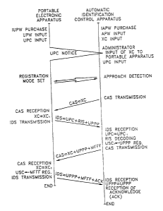
For example, as exemplified by FIG.15 which is a diagram of a sample house,
the present invention can set user-dependent levels of access for the entrance
and/or exit
through a given automatic identification door opening/closing device. For
example, the
user access code of each family member is registered in automatic
identification door
opening/closing devices I and II installed as the main entrance, an exterior
door and three
common-access doors, so that the entire family has access to the premises and
these
209894
19
rooms. Aecess to another room (e.g., the master bedroom) and another exterior
door is
controlled by an automatic identification door opening/closing device III, and
accordingly, certain family members' access codes are registered therein, so
that only
those family members have access to that room and that door. Further, the user
access
code of a particular family member may be registered in an automatic
identification door
opening/closing device IV corresponding to a special compartment (e.g., a
safe), and
accordingly, this family member has access to all areas, while certain family
members
are restricted to level II areas (e.g., children) and certain other family
members have
access to all but the level IV area. Only those household men;bers with
registered access
codes in the respective automatic identification door opening/elosing devices
are
authorized access thereto, to control the entry and exit of unauthorized
persons. Here,
since the pe:son in possession of a portable master key cannot recognize the
specific code
of an automatic identification door opening/closing device, a user access code
cannot be
registered without approval of the system's administrator. (In this case, the
administrator
may or may not be a family member.)
Also, as the portable master key only operates upon input of the user's
password,
even if the portable master key is lost or stolen, its use by third parties is
prevented since
the device automatically disables itself. Here, third party usage is curtailed
by way of a
predetermined time limit being applied to the enabled state upon input of the
user's
password. For example, if the predetermined time period from the enabled start
time has
passed, the portable master key is automatically disabled. Also, to
countermeasure theft,
whenever the portable master key is disengaged from its normal carrying mode,
it is
likewise disabled. Thus, by periodically verifying the normal carrying mode,
illicit third
party usage is checked. For example, if the portable master key is in the form
of a
wristwatch (FIG.2C) or buckle (FIG.2E), verification of the normal carrying
mode can
be determined by a switch being automatically operated as soon as the hasp is
unlatched
from its clasp, and for a ballpoint pen (FIG.2A), the switch may be installed
in the case
beneath a carrying clip and in opposition thereto. When the portable master
key in any
form is removed as by accident or theft, release of the above-mentioned switch
results
in automatically disabling password entry.
On the other hand, to avoid any behavior that the authorized person or the
user
lends an enabled portable master key to an unauthorized person, a video camera
apparatus
such as a camcorder, etc., may be installed in the entrance and exit gate.
Whenever the
249894
automatic identification control apparatus is operated, the camcorder is
operated, for
example, for three seconds, to take a picture of the passage of persons and
record the
photographed results. Since twenty persons per a minute can be photographed
with an
hour videe tape, total 1,200 passages can be photographed and recorded.
Accordingly,
5 the camera recorder can be efficiently controlled in comparison with the
conventional
photographing system which adopts a continuous photographing method or an
interval
photographing method.
The present invention also enables monitor and control of entrance and exit of
personnel and their office hours, as will be described below.
10 FIG.16 is a block diagram of an automatic identification door
opening/closing
device with which the office hours of personnel can be monitored and
controlled. FIG.16
further comprises clock means 300 and printer 310 in addition to the automatic
identification door opening/closing device of FIG.9. Clock means 300 divides a
predetermined clock signal to generate a data signal to measure seconds, and
further
15 divides this data signal to generate minute, hour, day and year signals.
Printer 310 may
be internally installed or connected via the I/O ports of a microcomputer as
an external
printer.
Here, whenever personnel in possession of portable master key 100 pass through
an automatic identification door opening/closing apparatus, his individual
identification
20 information and time of passage (supplied from clock means 300) are
checked, which are
then stored in storage means 240. Thus, if the printer is instructed to
generate an output,
control means 220 reads out the person's stored identification information,
for example,
employee number and office hours. Accordingly, workma hours and absenteeism is
checked and calculated, to be printed out on a record sheets as shown in
FIG.17. Also,
the present invention can control the comings and goings of personnel, while
recording
individual information as well as the time; thus enabling the accurate
monitoring of
personnel, and assisting in crime prevention and the tracing of criminals.
FEE-LEVYING CONTROL SYSTEM
FIG.18 is a view for explaining a fee-levying apparatus of an attendance fee
control system, and FIGs.I9A and 19B are a prospective view and a block
diagram of
the cash registering device for the prepaid method. Fee levying apparatus 600
is identical
to the above-mentioned automatic identification apparatus 200. Here, the only
difference
200~~9~~
21
is that the equipment to be operated is composed of a turnstile 270c, and when
a number
of gates are installed, a shielding wall 270d of the approximate height of a
person is
provided to avoid the RF interference with a neighboring gate. Also, in cash
registration
apparatus 700, automatic identification apparatus 200 further comprises
display 710,
receipt issuance portion 720, bank note identifier 730, I/O interface portion
740 and
floppy disk driver 750, with detection means 230 being deleted.
First of all, the operations of cash registration apparatus 700 and portable
electronic apparatus 100 will be described with reference to FIG.20.
The user inputs the UPW data to portable electronic apparatus 100, and presses
the "REGISTRATION" key to set a registration mode. Subsequently, if the user
presses
the "REGISTRATION" key via input means 210 of cash registration apparatus 700,
main
controller 220 instructs a CRT or a liquid crystal display portion 710 to
display '"specific
code." The user sees the displayed specific code XC and inputs the specific
code to
portable electronic apparatus 100. Subsequently, if a message to input user
information
(UPC) is displayed on display portion 710, the user inputs the UPC data via
input means
210. If a "TRANSMISSION" key is pressed after the UPC data is input, main
controller
220 transmits call signal CAS via transmitting means 250. Portable electronic
apparatus
100 detects the XC data loaded on the received call signal CAS. If the input
XC data
_ matches the received XC data, the call signal, in this case, IDS (UPC + RIS
+ UADD),
is transmitted. Here, UADD represents the address of the memory region where
the XC
data is stored. Cash registration apparatus 700 detects the UPC data from the
identification signal which is received via receiving means 280 to compare the
detected
UPC data with the input UPC data, and if a match is determined, the RIS signal
is
decoded, and the received UADD data is written as new UPC data. Accordingly,
the
user's secret access code is registered, and a call signal, in this case, CAS
(XC +
UADD + MADD), is transmitted. Portable electronic apparatus 100 receives the
call
signal and detects the XC data loaded on the received call signal. If the
detected XC data
matches the input XC data, the MADD data is written in a memory region USC for
the
corresponding user's secret code. Accordingly, registration of the specific
code and the
user access code is complete. Here, MADD represents the address of the memory
region
where the user access code is written. Subsequently, identification signal IDS
(UADD +
MADD + ACK) is transmitted.
Cash registration apparatus 700 receives the identification signal and detects
the
20~8~a~~
22
UADD loaded on the received identification signal. If the detected UADD is
identical to
the input UADD, completion of the registration of the specific code and the
user's secret
code is displayed, and then insertion of the bank note is required. If the
user inserts the
bank note through bank note insertion hole 731, bank note identifier 730
identifies a class
S of -the inserted bank note. Then, an amount of the identified bank note is
displayed on
display portion 710, and the inserted bank note is transferred to a bank note
storage unit.
Subsequently, after the bank note of the desired amount is inserted, the user
presses the
"TRANSFER" key. Then, main controller 220 loads on the call signal, data
corresponding to a prepaid amount (PPA) of money received according to the
transfer
key input for transmitting it.
Portable electronic apparatus 100 receives the call signal, that is, the CAS
(XC +
UADD + PPA), and detects the XC loaded on the received call signal. Then, if
the
detected XC is identical to the XC stored in address UADD, the PPA is written
in a
predetermined memory region 135 as shown in FIGS. If such writing is
completed, the
control means of the portable electronic apparatus instructs the display
portion to display
the amount of the written PPA, and transmits identification signal IDS (UADD +
MADD + ACK). Then, the operation is completed.
Cash registration apparatus 700 receives the identification signal and detects
the
UADD loaded on the received identification signal. Then, cash registration
apparatus 700
compares the detected UADD with the UADD written in address MADD. IF the
detected
UADD is identical to the written UADD, the reception is confirmed and the
receipt is
issued via receipt issuance portion 720. Then, the UPC and the UADD are
supplied to
fee levying apparatus 800 via I/O interface portion 740. At the same time, the
receipt
result is processed via the tloppy disk drive. As a result, the UPC and the
PPA are filed
on the floppy disk.
As described above, the PPA information is written in portable electronic
apparatus 100 using a prepaid method. Accordingly, portable electronic
apparatus 100
improves the prepaid function adapted in the conventional prepaying card,
e.g., a
telephone card, subway ticket, etc.
Referring to FIG.21, when a user in possession of the prepaid type of portable
electronic apparatus 100 passes through an entrance where levying apparatus
600 is
installed (e.g., cafeteria, movie theater, etc.), the appropriate fee is
automatically levied.
In other words, if a person possessing such a device in its enabled state
(i.e., his
20~8~9~~
23
password is entered) approaches a fee-levying apparatus as shown in FIG.18,
the control
means controls detection means 230 to detect the approach or passage of the
person, and
transmits call signal CAS (XC + UADD) via transmitting means 250.
Portable electronic apparatus 100 compares the received XC data and the XG
data
written in address UADD, and if a match is determined, transmits
identification signal
IDS (UADD + MADD + FLI). Fee levying apparatus 600 receives the identification
signal and compares the received UADD data with the UADD data written in
address
MADD, and if a match is determined, a fee-levying instruction FLI is decoded
and the
levied fee is calculated. Then, calculated fee information (CFI) is loaded on
call signal
CAS (XC + UADD + CFI) for transmission.
Portable electronic apparatus 100 compares the XC data of the received call
signal
with the XC data written in address UADD, and if a match is determined, the
amount
represented by the CFI data is subtracted from that represented by the PPA
data, and the
PPA data is updated with the subtracted result. After updating, identification
signal IDS
(UADD + MADD + ACK) is transmitted. Fee-levying apparatus 600 receives the
identification signal and confirms completion of the fee-levying operation.
Accordingly,
the UPC, CFI and current time information is tiled and stored. At the same
time;
turnstile 370c is unlocked so as to allow rotation, or the passage display
lamp is operated,
signifying completion of the above operation. At this time, a printed seat
ticket, i.e.,
theater or bus ticket, can also be issued.
PASSAGE FEE LEVYING SYSTEM
In a fee-levying system for use in connection with a toll road, parking lot or
subway, user transit distances and times vary greatly, so the fees vary
accordingly. When
2~ utilizing this embodiment of the present invention, the entrance location
and time of
entrance information are applied upon exiting.
FIG.22 is a view for explaining an automatic tee-levying system for a highway
toll gate. In FIG.22, automatic identification control apparatus 800 is
installed at an
entrance, and automatic fee-levying apparatus 900 is installed at an exit.
Automatic
identification control apparatus 800 comprises vehicle approach detection
sensor 801 and
vehicle pass detection sensor 802.
Referring to FIG.23, as a car and driver in possession of portable electronic
apparatus 100 approaches an entrance gate, entrance automatic identification
control
20989
24
apparatus 800 is enabled by vehicle approach detection sensor 801. Then, the
automatic
identification control apparatus 800 transmits call signal CAS (XC + UADD +
ELI).
Here, ELI is entrance location information.
Portable electronic apparatus 100 receives the call signal and compares the
received XC data with the XC data written in address UADD, and if a match is
determined, the received ELI data is written in the storage means. Then,
portable
electronic apparatus 100 transmits identification signal IDS (UADD + MADD +
ACK)
and completes the operation. Entrance automatic identification control
apparatus 800
receives the identification signal and confirms the reception of the
identification signal.
Then, the UPC data such as passage time information is filed and the operation
is
completed.
Referring to FIG.24, a car and driver having gained access through an entrance
gate approaches an exit gate, and automatic fee levying apparatus 900 is
enabled by
approach detection sensor 901 so as to transmit call signal CAS (XC + UADD).
Portable
electronic apparatus 100 receives the call signal and compares the received XC
data with
the registered XC data, and if a match is determined, portable electronic
apparatus 100
transmits identification signal IDS (UADD + MADD + ELI). Automatic fee-levying
apparatus 900 receives the identification signal and compares the received
UADD with
the registered UADD, and if a match is determined, automatic fee-levying
apparatus 900
calculates the CFI data based on the EL1 data stored in address UPC and the
received
ELI, and loads the calculated CFI data on call Slgllal CAS to transmit the
thus-loaded call
signal CAS (XC + UADD + CFI). Portable electronic apparatus 100 receives the
call
signal and compares the received XC data with the registered XC, and if a
match is
determined, the received CFI data is subtracted from the written PPA which is
then
updated with the subtraction result value. Finally, identitication signal IDS
(UADD +
MADD + ACK) is transmitted and the operation is completed.
Automatic fee levying apparatus 900 receives the identification signal and
compares the received UADD with the registered UADD, and if a match is
determined,
a crossing gate 940 is lifted and the green lamp in a display 950 is lit to
indicate
allowance of passage. Also, a camcorder 960 is momentarily operated for, say,
two
seconds, to record the passing vehicle. As the vehicle passes a gate, it is
detected by a
passage detection sensor 902, and then crossing gate 940 is lowezed and
display lamp 950
is turned off. Next, the UPC (vehicle type & number), ELI (place of access),
the CFI
209~~9e
(fee) and the time of passage information are all filed and the operation is
completed,
However, if the PPA data written in portable electronic apparatus 100 of the
passing
vehicle represents a smaller amount than that of the received CFI data,
instead of
confirmation signal ACK, portable electronic apparatus 100 sends an
"insufficient funds"
5 signal to automatic fee levying apparatus 900 which in turn transfers this
signal to
personal computer 910 to display the calculated fee on monitor 920 and
generate an alarm
signal. Upon notification of insufficient funds, the user may then pay in
cash, so that
crossing gate 940 can be raised by operation of keyboard 930. Reference
numeral 810
represents an electromagnetic shielding wall to prevent RF interference with
neighboring
10 gates.
The embodiment as described above relates to an automatic fee levying system
for
a highway toll gate. However, an automatic parking-fee-levying system of a
metered
parking area calculates parking fees based on entering and exiting times, and
can
automatically levy a calculated parking fee. Also, an automatic subway
boarding-fee-
15 levying system transmits place-of entrance information to the user's
portable electronic
apparatus via the entrance automatic identification control apparatus, and
upon exiting,
receives the place-of-entrance information and calculates the boarding fee, to
thereby levy
the calculated boarding fees from the PPA data written in the portable
electronic
apparatus. In this case, specific UPC information can be further provided,
e.g., special
20 fares for senior citizens, the military, students, etc. Accordingly, fare
gradation can be
done in the same manner as conventional subway-boarding-fee cal~!Vations.
AUTOMATIC CREDIT PURCHASE CONTROL SYSTEM
Referring to FIG.25, an automatic credit purchase system is installed in a
retail
25 outlet, e.g., department store, chain store, etc. Such a system comprises
automatic
identification control apparatus 200A, personal computer 200B, floppy-disk
drive 200C,
floppy-disk 200D, monitor 200E and keyboard 200F.
Referring to FIG.26, if a user purchasing a commercial product inputs his
password into portable electronic apparatus 100, and stands in front of
automatic
identification control apparatus 200A, call signal CAS (XC + UADD) is
transmitted
upon approach detection. Portable electronic apparatus 100 receives the call
signal and
compares the received XC data with the registered XC data, if a match is
determined,
identification signal IDS (UADD + MADD) is transmitted. Automatic
identification
2098~Oe
~6
control apparatus 200A receives the identification signal and compares the
received
UADD with the registered UADD, and if a match is determined, the UPC (personal
identification and account numbers) is displayed on monitor 200E via personal
computer
200B. The administrator then confirms whether the displayed information agrees
with the
personal identification information supplied by the user, and if so, the price
of the
purchased product is input via keyboard 200F. Then, if the "ENTER" key is
pressed, the
purchasing amount information (PAI) corresponding to the calculated total is
transferred
to automatic identification control apparatus 200A. Next, automatic
identification control
apparatus 200A transmits call signal CAS (XC + UADD + PAI). Portable
electronic
apparatus 100 receives the call signal and compares the received XC data with
the
registered XC data, and if a match is determined, stores the received PAI data
and
transmits identification signal IDS (UADD + MADD + ACK), thus completing the
operation.
That is, automatic identification control apparatus 200A receives the
identification
signal and compares the received UADD with the registered UADD, and if a match
is
determined; acknowledges the reception of the identification signal and
controls the
receipt issuance unit to issue a receipt. Then, the UPS-plus-PAI information
is ailed on
floppy-diskette 200D of floppy-diskette driver 200C via personal computer 200B
and the
operation is completed. Here, when the seller or the administrator presents
the floppy-
diskette to the credit card company or bank, the transaction amount is
remitted. The
credit card company or bank then deducts the amount from the client's account,
and
sends notification to the client.
AUTOMATIC BANKING SYSTEM
Referring to FIGs.27A and 27B, an automatic banking system according to the
present invention is installed at a bank. Here, an automatic banking system
100 comprises
transmitting means 1010, receiving means 1020, a slip issuance portion 1030, a
coin
processing portion 1040, a bank note processing portion, display and key input
means
1060, a main controller 1070, a filing portion 1080, an I!O interface portion
1090 and
an power supply portion 1100. Also, a coin outlet 1042, a bank note
inlet/outlet 1051 and
a CRT 1061 are installed in the horizontal surface of the panel of automatic
banking
system 1000. Further, a contact panel switch 1062 is fixed on the surface of
CRT 1061
to sense contact with the surface and the location thereof, and at each step
of a
~098~94
27
transaction, mode selection keys and/or data keys are displayed on CRT 1061,
and
contact panel switch 1062 detects key input as with any keypad. A slip
issuance portion
1030 prints deposit slips, withdrawal slips, or remittance slips to other
accounts, and
discharges the printed slip through slip outlet 1031. A coin processing
portion 1040
discriminates denominations and counts the money entering a coin inlet 1041,
with slugs
and damaged coins being discharged via coin outlet 1041. Also, a bank note
processing
portion 1050 discriminates denominations and counts the money entering a bank
note
inletloutlet 1051, with counterfeit notes being rejected. For cash withdrawal,
coins are
dispensed via a coin outlet 1042 and bank notes are dispensed via bank note
inlet/outlet
1051. A main controller 1070 is connected with the host computer via I/O
interface
portico 1090 for on-line connections, to process transactions automatically. A
filing
portion 1080 composed of a floppy-diskette driver is controlled in case of off-
line
connections. Reference numeral 1110 is power and call key input portion in
which
reference numeral 1111 is a power key and 1112 is a clerk call key.
Operation of the automatic banking system having such a construction as
described
above and according to the present invention will be described below with
reference to
FIG.28.
A user, while in possession of portable electronic apparatus 100, enables
automatic banking system 1000 by pressing a power key 1 I 11, thus displaying
a greeting
''0 on CRT 1061, for example "HELLO... PLEASE WAIT A MOMENT," as shown in
FIG.29A, and transmitting call signal CAS (XC + UADD) via transmitting means
1010.
Portable electronic apparatus 100 receives the call signal and compares the
received XC
data and the XC data stored in address UADD, and if a match is determined,
identification signal IDS (UADD + MADD + BALANCE) is transmitted. Automatic
banking system 1000 receives the identification signal and compares the
received UADD
data with the UADD registered in address MADD, and if a match is determined,
CRT
1061 displays the user's account number, the received balance according to the
UADD
data and a prompt, for example "CONFIRMED... PLEASE SELECT MODE," as shown
in FIG.29B. The user then selects the desired mode key: deposit, withdrawal or
remittance.
If, for example, the deposit mode key is pressed, CRT 1061 displays an
appropriate prompt message, e.g., "PLEASE ENTER DEPOSIT AMOUNT" as shown
in FIG.29C. Then, the user deposits his amount via bank note inlet/outlet 1051
and/or
209~~9~
28
coin inlet 1041, so that automatic banking system. 1000 can count the
deposited money
via bank note processing portion 1050 and coin processing portion 1040, and
displays the
recognized amount on CRT 1061. Upon pressing an "ENTER" key, the recognized
amount is added to the balance of the user's account, to update the old
balance with a
new balance and transmit call signal CAS (XC + UADD + UPDATED BALANCE) via
transmitting means 1010. Portable electronic apparatus 100 receives and
acknowledges
the call signal, and then stores the received updated balance. Then, portable
electronic
apparatus 100 transmits an identification signal for confirmation, which
terminates the
program. Automatic banking system 1000 receives the identification signal and
confirms
reception. When reception is confirmed, a "THANK YOU?" message or the like is
displayed on CRT 1061, as shown in FIG.29D. Then, a deposit slip is issued via
slip
issuance portion 1031. At this time, in case of on-line connections,
information pertaining
to the user's account number, deposited amount and updated balance is
transmitted to the
host computer via I/O interface portion 1090. This information can be stored
in filing
portion 1080 if not on-line, which also terminates the program.
In the withdrawal mode, as shown in FIG.29E, an appropriate prompt is
displayed
on CRT 1061, for example "PLEASE ENTER WITHDRAWAL AMOUNT." When the
user enters the desired amount and denomination by pressing the ten key
display on CRT
1061 and presses the "ENTER" key, the entered amount is subtracted from the
balance
and the old balance is updated with a new balance. Then, call signal CAS (XC +
UADD + UPDATED BALANCE) is transmitted. Next, portable electronic apparatus
100 receives the call signal and stores the updated balance. Then,
identification signal
IDS (UADD + MADD + ACK) is transmitted. Automatic banking system 1000 receives
the identification signal and confirms reception. Once the reception is
confirmed, the
withdrawn amount is discharged through coin outlet 1042 and bank note
inlet/outlet 1051
according to the selected denominations. Then, a withdrawal slip on which the
date of
withdrawal, amount, etc., are printed is issued through slip outlet 1031.
Also, as in the
deposit mode, the withdrawal information is transmitted and tiled, to then
complete the
operation.
At the remittance mode, as shown in FIG.29F, a juidance statement of "PLEASE
INPUT YOUR ACCOUNT NUMBER AND REMITTANCE AMOUNT OF MONEY"
is displayed on CRT 1061. If. the user inputs the receiver's account number
and the
remittance amount of money and then presses the "ENTER" key, the corresponding
2p98~9~
29
remittance amount of money is deducted from the balance and call signal CAS
(XC +
UADD + UPDATED BALANCE) is transmitted. Then, if portable electronic apparatus
100 responds to the call signal and transmits the identification signal,
automatic banking
system 1000 receives the identification signal and confirms the reception.
Then, the
remittance slip in which the remitting date, the receiver's account number and
the
remittance amount of money, ete are printed is issued and the remittance
information is
transmitted to the host computer via I/O interface portion 1090. Thus, the
operation is
completed.
As described above, in the automatic banking system according to the present
invention, deposits, withdrawals and remittances can be automatically
processed. Thus;
the card, bankbook transfer mechanism, bankbook printing apparatus, etc.,
which are
necessary for the conventional IC card system are unnecessary with the present
invention,
because the portable electronic apparatus can replace the bankbook.
Accordingly, the
at!tomatic banking system can be simply constructed, to reduce costs. Also,
since the user
does not need to have separate bankbooks for each bank or each account, he can
integrate
and control the various conventional bankbooks with a single portable
electronic
apparatus. Also, the user can check on his banking transactions at any time or
place via
the display means of the portable electronic apparatus.
2U In the electronic identitication system having remote automatic response
performance of the present invention as described above. if the user Nnrchases
a portable
electronic apparatus and registers it with an automatic identification control
apparatus,
each can communicate with the other. Accordingly, the present invention
facilitates
registration and administration, in comparison with the conventional IC card.
Further,
using the integration-control features of the portable electronic apparatus
and an intended
automatic identification control apparatus, the present invention provides for
freely
accessing a residence, office or public facility equipped with the control
apparatus,
whenever a user is in possession of the portable electronic apparatus. Also,
once the
password is input, the conveyance of the access code of a registered portable
electronic
apparatus is carried out without manipulation. Accordingly, the present
invention
enhances convenience.
Also, since the portable electronic apparatus and the automatic identification
control apparatus are registered with each other for mutual identification,
security is
~098~94
~o
increased. In the registration procedure, since neither the user nor the
administrator
expose their password or specific code and the actual registered code is
different from
the exposed code, neither party can recognize the registered code.
Accordingly, neither
the user nor the administrator can commit fraud or fabricate substitute
devices, thereby
greatly increasing reliability and safety.
Also, both prepaying and credit purchase methods are possible, to absorb and
integrate existing card systems.
Also, since the present invention can be applied to a toll gate system,
traffic
bottlenecks at toll booths are reduced.
The present invention is not limited in the above embodiment, and may be
variously modified within the spirit of the technical concept of the
invention.