Note: Descriptions are shown in the official language in which they were submitted.
2 -):L :
Description
Visual Panel
Technical Field
The present invention relates to a visual panel such as
a lane decoration panel in a bowling alley, a display panel
for outdoor-wall and roo~top advertizement, and a display
panel for advertizement in station precincts.
,
Backqround Art
- In a bowling alley, Eor instance, a wall is used for a
lifting device portion of an apparatus for automatically
aligning and arranging bowling pins at a distal end of a
lane so as to cover and conceal the lifting device portion
from a competitor. Conventionally, the nu~ber of unknocked-
down pins and the like are displayed on this wall by
electric light.
Recently, the display of the number of unknocXed-down
pins and the like has eome to be given on a table or the
like on the competitor's side. Instead of the electric-
light display of the number of lmknocked-down pins and the
like, a multiplicity of panels on which pictures,
photographs or the like are printed have come to be '
installed on the walIs f~r~covering and concealing the
lifting device portion, so as to~create a unique, ~avorable
.
atmosphere of the interior~of the bowling alley from the
viewpoint of vision.
In~many cases, however, such panels on which pictures,
photographs;or the like~are printed are periodically
~ replaced with new panels;on which different pictures,
; photographs or the like~are printed, so as to renew the
atmosphere 'of the interior of the bowling alley. Yet, since
such panels have a s~ize of approximately 3 m x 1 m or
thereabouts, much expense is required in the replacement
....
operation, particularly in transportation, so that such
panels are not necessarily satisfactory.
Such a problem is not restricted to panels in bowling
alleys, and also occurs in the case of panels for rooftop
advertizement which are periodically replaced.
The present invention has been devised in view of the
above-described aspects, and its object is to provide a
visual panel which facilitates transportation thereof and is
thereby capable of reducing the replacement cost.
1 0 ,
Disclosure of Invention
_ In accordance with the present invention, the
aforementioned object is attained by a visual panel
comprising: a frame; a flexible sheet having swollen
portions at opposing edge portions thereof, respectively;
and shee-t stretching means for slidably accommodating the
swollen portions at the opposing edge portions of the sheet
and for stretching the sheet over the ~rame.
As a preferred example of the stretching means in
accordance with the present invention, the stretching means
comprises a first stretching device for slidably
accommodating the swollen portio~ at one edge portion of the
sheet and a second stretching device for slidably
accommodating the swollen~portion at the other edge portion
of the sheet, wherein the first stretching device and the
second stretching device are~each provided with a hole for
accommodating the swollen portion at the edge portion of the
sheet and a slit through which the edge portion of the sheet
~ contlnuing to the swollen portion is inserted. Here, in one
30 example, at least one of the first str~tching device and the ;~
second stretching device is secured to the frame or is
disposed movably with respect to the frame. The frame and
the stretching means may be formed of any of wood, metal,
synthetic resin, and the like, but may pre~erably be formed
of a hard plastic or aluminum, most preferably aluminum, in
view of the mechanical strength or the light-weight
characteristic.
In accordance with another aspect of the present
invention, the visual panel further comprises tension
adjusting means for adjusting a tension applied to the
sheet. In the visual panel having such tension adjusting
means in the present invenkion, it suf~ices if the first
stretching device is secured to the frame, and the second
stretching device is disposed movably with respect to the
frame, wherein the tension adjusting means is provided
between the second stretching device and the frame. In
a~ot~er form, it suffices if the first stretching device and
the second stretching device are disposed movably with
respect to the frame, wherein the tension adjusting means is
disposed between the ~irst stretching device and the second
stretching device.
This tension adjusting means may be comprised of any of
a ratchet-type lashing belt, a turnbuckle, a rubber band- ;
type lashing belt, or a cam buckle-type lashing belt which ~;
; ~ ~20 are provided with hooks at both ends.
The flexible sheet in the present invention may be a -~
general sheet, such as~a nylon sheet or a vinyl sheet
obtained by extrusion molding,~ or a cloth or a nonwoven
sheet formed of natural fibers or chemical fibers or a
combination thereof. In a case where illumination is
provided from the rear surface of the sheet, a back-lit type
may preferably be used as the sheet. As the swollen portion
of the sheet, it is possible to use one in which the edge ~'
portion;of the sheet itself is made to swell by being
integrally formed, or one which i;s ob~ained by tucking in
the edge portion of the sheet itself. Furthermore, the
swollen portion may~be~one in which the edge portion is
turned up and sewn together, and~a flexible rope is inserted
into a loop formed;~herein. The cro;ss-sectional
configuration of this swollen portion may be a circular,
triangular, quadrangular, or other polygonal shape. The
x ; l
flexible sheet may preferably be slightly stretchable, but
if it is excessively stretchable, there are cases where the
picture or the like formed by printing or the like is
distorted.
In accordance with the visual panel of the present
invention, a picture, a photograph or the like is printed in
advance on the flexible sheet. This sheet is stretched over
the frame by using the stretching means, and is mounted in,
for instance, a bowling alle~ or the like. When it is
desirous to change the atmosphere of the interior of the
bowling alley, the sheet is removed from the frame, and a
sheet-with a new different picture, a photograph or the like
printed thereon is stretched over the frame. At that time, ;~
if the new and old sheets are transported in a rolled-up
state, the operation does not take up much space and is
facilitated remarkably.~
In accordance with the visual panel of the present
invention, since the portion where a picture, a photograph
or the like is printed is the flexible sheet and is arranged
~20 to be removable, replacement and transportakion thereof are
very easy. As a result, the operating efficiency is
improved remarkably, and~the replacement cost can be
reduced.
Hereafter, a more detailed~d~escription o~ the present
~25 invention will be given'on the basis o~ specific examples
shown in thé drawings. ~Hence, the above-described invention
and other-aspects~of the~lnvention will become more
apparent. It should be noted that the present invention is
not restricted to these specific examples.
Brie~ Descri~tion of Drawinas
Fig. 1 is a perspective view of the interior of a
bowling alley in which a~préferred em~odiment of the presenk
invention is used;'
~Fig. 2 is a front elevational view of a state in which
a sheet is removed 1n the embodiment shown in Fig. 1;
: :.
Fig. 3 is a left-hand side elevational view of the
example shown in Fig. 2;
Fig. 4 is a rear view of the embodiment shown in Fig. :~:
l;
S Fig. 5 is a cross-sectional view taken along line V - V
shown in Fig. 1;
Fig. 6 is a detailed perspective view of a second
stretching device and the like shown in Fig. 5;
Fig. 7 is an overall perspective view of the sheet
shown in Fig. 5;
Fig. 8 is a cross-sectional view of another preferred
e~bod-iment of the present invention, and corresponds to Fig.
5;
Fig. 9 is a perspective view of another example in ~:
which the embodiment shown in Fig.~ 8 is used;
Fig. 10 is a perspective view of another example of the
sheet used in the present invention; :
- Pig. 11 is a cross-sectional view of still another
:: preferred embodiment of the present invention;
... . .
~ Fig. 12 is a front elevational view in which the sheet
; and the like are removed in the:embodiment shown in Fig. 11;
Fig. 13 is a side elevationaI view of the embodiment
: shown in Fig. 11; and : ~ ;
Fig. 14 is a perspective view of a coupler used in the
:embodiment:shown in Fig. 11.
, : :
Best Mode f~r Carr~inq Out the Invention
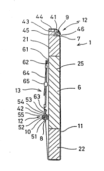
:In Figs. 1: and 7, one visual panel 1 in this embodiment
is allotted to each of two lanes 3 in such a manner as to
cover and conceal from a competitor a lifting device portion
: of an apparatus ~or automatically aligning and arranging
bowling pins 4 at a:distal end of the lane 3 in a bowling
alley 2. :The visual panels ~ are disposed in a series by
:: being supported by:columns 5~rotatably in the direction of
: 35 A. Each visual panel I comprises a:frame 6; a flexible
sheet 11 having swollen portions 9 and 10 at opposi~e edge
), ....
-6-
portions 7 and 8; sheet stretching means 12 for slidably
accommodating the swollen portions 9 and 10 at the opposite
edge portions 7 and 8; and tension adjusting means 13 for
adjusting the tension applied to the sheet 11.
The frame 6 has upper and lower hor.izontal members 21
and 22, left and right vertical members 23 and Z4, and a
plurality of intermediate vertical members 25, which are
connected to each other by means of screws or the like. The
frame 6 is disposed in such a manner as to be rotatable in
10 the direction of A by means of hinge mechanisms comprised of ~-
shafts 26 and bearings (not shown) disposed in the left and
right-vertical members 23 and 24.
The swollen portion 10 at the edge portion 8 of the ;
sheet 11 is formed such that the edge portion 8 is turned up
and sewn together, and a flexible rope 32 is inserted into a
loop formed therein. The other swollen portion g is also
formed in the same way as the swollen portion 10.
The stretching means 12 has a first stretching device
41 for accommodating the swollen portion 9 at one edge -;
~ 20 portion 7 of the sheet 1~1 and a second stretching device 42
;~ ~ for accommodating the swollen portion 10 at the other edge ;,
portion 8 o~ the she~et 11. The stretching~ device 41 has a
notch 43 formed~in a front apex portion of the horizontal
member 21 of the frame 6 and a cover plate 44 covering the
~25 notch 43 and~secured~to the horizontal member 21 by means o~ ;~
screws or the like. Formed in the stretching device 41 is a
hole 45 ~or slidab1y~accommodating; the swollen portion 9 at
the edge portion 7~ of the~sheet 11 by being~surrounded by
the curved cover plate 44 and the notch 43. In addition,
the tip of the cover plate 44 ~lS disposed with a slight gap
-between the same and~the~horizontal;member 21 so as to form ~.
a slit: 46 through which the;~edge portion 7 of the sheet 11
which continues to the~swollen por ion 9 is inserted. Thus
: :the f irst stretching device~41 secured to the frame 6 has
~ 35 the hole 45 for slidably accommodating the swollen portion 9
: ' at the edge portion 7 of the~sheet~ll and the slit 46
:
':
through which the edge portion 7 of the sheet 11 which ~.
continues to the swollen portion 9 is inserted.
The stretching device 42 which is elongated has a
cylindrical portion 52 having a slit 51 and a plate-like .
5 portion 54 formed integrally with the cylindrical portion 52 :
and having a plurali~y o~ rectangular through holes 53. In
the stretching device 42, the inner space of the cylindrical
portion 52 is formed as a hole 55. Hence, the second
stretching device 42 disposed movably with respect to the
frame 6 has the hole 55 for slidably accommodating the
swollen portion 10 at the edge portion 8 of the sheet 11 and ~:
t~e sll.t 51 through which the edge portion 8 of the sheet 11
which continues to the swollen portion lO is inserted.
The tension adjusting means 13 ~or adjusting the
tension applied to the sheet ll has the following: hook
retainers 61 which are respectively secured to the vertical
members 23 and 24 and the intermediate vertical members 25
by means of screws or the like; hooks 62 which are
: respectively retained at the hook retainers 61; other hooks
63 retained at the plate-like portion 54 through the through
hoIes 53, respectively; lashing belts 64 each stretched
between the hooks 62 and 63; and buckles 65 each attached to
the lashing belt 64:so as to adjust the distance between the
: hooks 62 and 63. In the above-described manner, the tension
adjusting means 13 is disposed between the stretching device
42 and the frame 6.:
The ~isual panel:1 formed as described above is
disposed at the distal end of each lane 3 in the bowling
alley 2, as shown in Fig. 1. By means of, for instance, a
photograph printed on the front of the sheet 11 of the
visual panel 1I the atmosphere of the interior of the
bowling alley 2 is made a visually pleasing one. When it is
desirous to change the~atmosphere o~ the interior of the
bowling alley 2, the following procedure is taken: The
visual panel 1 is rotated in the direction of A to cause the
rear surface of the visual panel 1 to face the operator'a
~'1 f~ r~, ''' '' ,'' . .
side; the tension applied to the sheet 11 by means of the
lashing belts 64 is alleviated; the swollen portlons 9 and
10 are pulled out of the respective holes 45 and 55; the
sheet 11 is removed from the frame 6; the swollen portion 10
5 of a new sheet 11 is inserted into the hole 55 in the ;
horizontal direction, as shown in Fig. 6; and the other
swollen portion 9 is similarly inserted into the hole 45 in
the horizontal direction, thereby fitting the sheet 11 on
the frame 6. Subsequently, one ends of the lashing belts 64
are pulled to impart an appropriate tensile force to the
sheet 11, thereby stretching the sheet 11 tautly.
- -The visual panels 1 make it possible to change the ;~
atmosphere of the in~erior of the bowling alley 2 simply by
changing the sheets 11. In addition, since the sheets 11
rendered unnecessary after being replaced and the new sheets
11 are flexible, they can be transported by being folded up
or rolled up. Hence, the transportation of these sheets is
not troublesome, and a multiplicity of sheets can be
transported at one time, with the result that the operating
efficiency is improved remarkably.
In the above-described embodi~ent, the visual panel 1
is formed by the first stre~ching device 41 secured to the
frame 6 and the second stretchlng device 42 disposed movably
with respect t~the frame 6. Instead of this arrangement,
an arrangement may be alternatively provided as shown in
Fig. 8. Namely! a first stretching device 71 for
accommodating the;swollen portion 9 at one edge portion 7 of
the sheet 11 is formed in the same way as the stretching
device 42, the hooks 62 are retained at the plate-like
portion 54 of the stretching device 71 via the through holes
53 formed in the plate-like portion 54. Thus, the first and
second stretching devices 71 and~42 are disposed movably
:
with respect to the frame 6, and the tension adjusting means
13 is disposed between the first stretching device 71 and
the second stretching device 42, thereby forming a visual
paneI 72.
'
-9- ::
In this visual panel 72, the sheet 11 is stretched
while being guided by space-forming members 73 and 74
attached to the upper and lower horizontal members 21 and 22
of the frame 6 by means of screws or the like, and a space
76 is formed between a front surface 75 of the frame 6 and
the sheet 11 opposing the front surface 75 by means of the
space-forming members 73 and 74. In this space 76,
illuminating devices 77 such as fluorescent lamps may be ;~
provided, as required, and the sheet 11 may be illuminated
from the rear by the illuminatin~ devices 77, thereby
obtaining a more favorable visual ef~ect. In the visual
p~nel-72 of this embodiment, covers 83 and 84 are
respectively fitted at upper and lower ends of the frame 6
via mounting plates 81 and 82 secured to the frame 6 by
means of screws or the like. A plurality of through holes
85 and 86 through which the lashing belts 64 can be inserted
are formed in the mounting plates 81 and 82 in
correspondence with the through holes 53.
Although, in the above embodiments, a description has
been given of the use of the visual panels 1 and 72 in the
bowling alley 2, the visual panel of the present invention
is not limited to such use. For instance, as shown in Fig.
9, an arrangement may be provided ~such that U-shaped support
members 93 and 94 each having a bottom plate 92 are ~ixed to
~25 an enclosing wall 91 provided in such a manner as to
surround a construction site, and the visual panel 72 is
inserted thereinto to give a display for the construction
site. In this case, if the illumination device 77 is
mounted in the visual panel 72, a display can be provided
favorably even at night. To change the contents of the
display, it suf~ic~s if the sheet 11 is replaced as
described above.
. .
As the sheet, although in the above example~ a
description has been given of a rectangular sheet 11 ha~ing
the swollen portions 9 and 10 at the upper edge portion 7
and the lower edge portion 8, as shown in Fig. 7, it is
2 ~' -' '; ' !
- 1 0 -
possible to use, instead, a sheet 105 in which, in addition
to the swollen portions 9 and ~0, additional swollen
portions 103 and 104 are respectively formed in horizontally
projecting portions 101 and 102, as shown in Fig. 10. When
the sheet 105 is used, the frame 6 is enveloped by the sheet
105, and stretching devices and tension adjusting means are :~
also used for the swollen portions 103 and 10~ in the same
way as described above. If this arrangement is adopted, a
tensile force can be imparted to the sheet 105 in the :~
horizontal direction as well, so that the sheet can be
stretched more tightly in some cases.
- ~eferring now to Figs. 11 to 14, a description will be
given of still another emkodiment of the present invention.
A visual panel 201 of this embodiment comprises the
flexible sheet 105 having the swollen portions 9 and 10, and
103 and 104 at the two sets of opposing edge portions; sheet
stretching means 203 for slidably receiving the swollen
portions 9 and 10 at the opposite edge portions o~ the sheet
105 and for stretching the sheet 105 over a frame 202; and
tension adjusting means 204 for adjlsting the tension
applied to the sheet 105.
The frame 202 of this embodiment includes a pair of
vertical members 210 (one is not shown) disposed in
parallel; horizontal members 211 and 212, and 213 and 214
whose ends are respectively secured to the pair of vertical
members 210 by welding or other similar means and which are
disposed in parallel with each other by bridging the pair of
vertical members 210; and cylindrical members 215, 2~6 and :
217 disposed in parallel with each other in the same way as :
these horizontal members 211, 212, 213 and 214. :~
In~ermediate vertical members are provided on the frame 202
in parallel with the vertical members 210, as required.
Secured to respective one ends of the cylindrical members
215 and 216 are other ends of brackets 221 and 222 whose one
ends are secured to the vertical members 210 by means of
welding or the like. Thus, respective one ends of the
t
cylindrical members 215 and 216 are supported by the
vertical members 210 via the brackets 221 and 222. The
other ends (not shown) o~ the cylindrical members 215 and
216 are also supported by brackets similar to the brackets
221 and 222. In addition, brackets similar to the brackets
221 and 222 may be provided between intermediate portions of
the cyli.ndrical members 215 and 216 on ~he one hand, and the
horizontal members 213 and 214 or the intermediate vertical
members on the other, so that the intermediate portions of
the cylindrical mernbers 215 and 216 will not be deflected.
The cylindrical member 217 bridges and secures the pair of
. vertical members 210 in the same way as the horizontal
members 211 and 212.
It should be noted that a cover 231 is secured to the
pair of vertical members 210 and the horizontal members 211
and 212 by means of fitting, screws or the like in such a
manner as to cover the outer sides of these members.
In the stretchi.ng means 203 of this embodiment, a first
stretching device 241 for accommodating the swollen portion
9 at one edge portion of the sheet 105 and a second
stretching device 242 for accommodating the swollen portion
10 at the other edge portion of the sheet 105 are each
provided with couplers 251 and 252 and a plurality of
adjusters 253 and 254. The coupler 251 is formed as being
identical to the coupler 252, and the adjuster 253 is formed
as being identical to the adjuster 254. Accordin~ly, a
description will be given hereafter of only the coupler 251
and the adjuster 253. .
As~shown in Fig. 14, the elongated coupler 251 has a
hole 261 for accommodating the swollen portion 9 at one edge
: portion of the sheet lD5; a slit Z62 through which the edge
portion of the sheet 105 continuing to the swollen portion 9
is inserted; a hole 264 for slidably accommodating a swollen
portion 263 of the adjuste~ 253; and a s~it 266 through
which a plate-like por:tion 265 of the adjuster 253
continuing to the swollen portion 263 is inserted. The ~.
~ ~; J~
-12-
holes 261 and 264 and the slits 262 and 266 are provided
over the entire length of a body 267 of the coupler 251.
Each of the adjusters 253 is provided with the swollen
portion 263 and the plate-like portion 265 formed integrally
with the swollen portion 263, as described above. A hollow
portion 271 and a slit 272 communicating with the hollow
portion 271 are formed in the swollen portion 263, and an
elongated hole 273 is formed in the plate-like portion 265.
The insertion of the swollen portions 9 and 263 into
the holes 261 and 264 is effected from the horizontal
direction in the same way as the example described by using
Fig. ~. As a result of the fact that the swollen portion
263 is slidably accommodated in the hole 264, the position
of each of the adjusters 253 is adjustable in the direction
o~ X with respect to the coupler 251, i.e., with respect to
the longitudinal direction of the coupler 251. A hook
portion 283 of a fixed coupler 282 having one end 281
secured to the vertical member 210 by means of welding or
the like is retained at the elongated hole 273 in the
adjuster 253. I'he stretching device 241 is thus coupled to
the frame 202. It should be noted that, in the fixed
coupler 282, a portion between its one end 281 and the hook
portion 283 may be formed by a coil spring. A belt 291 of
the tension adjusting means 204 is inserted through an
elongated hole (not shown~ in the plate-like portion of the
adjuster 254 which is formed in the same way as the adjuster
253.
The tension adjusting means 2~4 has the belt 291 and a
buckl~ 292 connected to the belt ~91. The belt 291 is
inserted through the elongated hole Inot shown) in the
plate-like portion of the adjuster 254, as described above,
and is trained to the cylindrical member 217. As a result,
if one end 293 of the belt inserted through the buckle 292
is pulled, the distance between the adjuster 254 and the
cylindrical member 217 can be shortened, thereby making it
possible to stretch the sheet 105 tautly.
~.~
- 13 -
It should be noted that, in the visual panel 201,
arranyements similar to those for the stretching devices 242
and the tension adjusting means 204 are provided for the
swollen portions 103 and 104 of the horizontally projecting
portions 101 and 102, so that the sheet 105 is stretched
tautly in the hori~ontal direction as well.
The visual panel 201 of this embodiment is ~urther
provided with an edge cover 301 attached to the cover 231
rotatably in the direction of R via hinges 300 and a rear
plate 302 having its peripheral edges fitted to the cover
231. The edge cover 301 can be secured to the cover Z31 by
means-of screws 303, so that if the screws 303 are removed,
the edge cover 301 is rot~table about the hinge 300 in the
direction of R. ~ pad 305 is fitted to inner peripheral
edges of the edge cover 301. The pad 305 clamps the sheet
105 in cooperation with the cylindrical members 215 and 216
and stretches slight creases and the like occurring in the
sheet 105 to prevent them fro~ occurring. Holdin~ members
306 and 307 are attached to the vertical members 210 by
means of welding or the like so as to hold the edge cover
301 securely when the edge cover 301 is closed. In this
embodiment as well, a multiplicity of fluorescent lamps 310,
which are illuminating means, may be attached to the frame
202 via supports 311. In addition, in order to mount the
~25 visual panel 201 onto a wall or the like, mounting devices
321 and 322 may be a~tached to the ~ertical rnembers 21Q and
the like by means of welding or the Iike. The mounting
devices 321 and 3~2 are each constituted by a member 323
welded to the yertical member 210 or the like and a bracket
325 secured to the member 323 by means of bolts 324
~ .
The visual panel 201 formed as described above is
mounted onto, for instance, an enclosure frame or the like
at a construction site via horizontal pipes or hori~ontal
bars 326 welded onto the brackets 325. With the visual
panel Z01 as well, if the edge cover 301 is rotated in ~he
direction of R a~ter removing the screws 303, and if the
'~.
~/ ~r;~'; i
-14-
belts 291 are then loosened to slacken the sheet 105, and
the swollen portions 9 and 10 are drawn out from the
couplers 251 and 252, the replacement of the sheet 105 can
be performed easily.
Although in the above-described embodiments the sheet
is provided only on one side of the frame, the sheet may be
provided on both sides of the frame, in which case the
illuminating devices may also be provided between the frame
and the respective sheets. Furthermore, the visual panel~
may be arranged in ~he shape of a prism, e.g., a
~uadrangular prism, and castors may be provided at the lower
ends of the visual panels so as to render the visual panels
movable.
Although, in the sheet 105 shown in Fig. 10, the
horizontally projecting portions 101 and 102 project
orthogonally with angular portiohs, the present invention is
not restricted to such a sheet 105. For instance, this
horizontally projecting portion may be formed in such a
manner as to project with smooth arcuate edges 330.
: .
;',,'
"'
:.:
- : ;,
:
' '.
~',
,:.;.
,:
'~'
' '