Note: Descriptions are shown in the official language in which they were submitted.
CA 02098979 2000-09-15
IMPROVED BATTERY REFILL SYSTEM
Background of the Invention
The present invention relates generally to a battery refill
system used for filling battery cells to a predetermined level, and
for automatically monitoring and maintaining the battery cells at that
level. More particularly, the present invention defines the material
parameters of tubing which has found a particularly advantageous use
within the battery refill system. This tubing may be used with any of
the inventions, and particularly the refill valves, disclosed in U.S.
Patent Nos. 5,048,557 and 5,090,442.
It is standard practice in the field of industrial battery
watering to use a flexible polyvinyl chlorine ("PVC") thermoplastic
tubing to interconnect automatic shut-off valves (such as those
disclosed in U.S. Patent Nos. 5,048,557 and 5,090,442) which are
mounted on each cell of a battery to be filled within a battery
watering system. The watering system is intended to last the life of
the battery (five years or longer) . A common water supply feeds water
to each cell through the thermoplastic tubing.
It has been widely observed that the thermoplastic tubing mounted
on such battery cells tends to discolor, soften, and tactify with age.
It was assumed that the softening was generally insignificant and that
the discoloration and tactification were due
2
~ 'l. i art i ~R
i..1 ~f.~ YJ V.9 Yr~ ': ''v
to acid fumes and electrolyte migration occurring during the
battery charging cycle. However, these thermoplastic tubing
characteristics were not perceived as problems which would affect
the reliability of the watering system, so long as no leakage
occurred within the tubing. While it was felt that acid fumes and
electrolyte migration might cause refill valves to lock in an open
or closed position, the mechanism by which this occurred was not
completely understood. In fact, it was previously understood that
it was the evaporation of the fluid used to fill the battery cells
LO which left a sticky residue between the main valve and seat, such
as might create a premature shut-off condition (see U.S. Patent No.
5,048,557).
A primary reason automatic watering systems are not more
widely used is their susceptibility to apparent random failure due
to valve contamination. It has been assumed that the specific
source of_ the contamination is either sticky residue from the
inside of the battery cells migrating into the valves, or
contaminants carried by the water supply into the valve by the
thermoplastic tubing.
20 It is now understood that PVC thermoplastic tubing
deteriorates in a fashion which is particularly damaging to the
refill valves used in a battery watering system. Specifically, it
has been experimentally determined that the tactification found to
occur within the thermoplastic tubing after a relatively short
3
~~41~~')'l~Ia ~~
period of service on the top of the battery is not simply acid
residue collecting on the tubing surface; rather, it is caused by
a separation of the plasticizes found within such tubing from the
plastic resin. This plasticizes °'blee~ding" allows the plasticizes
to collect as a liquid on both the inside and the outside of the
tubing. Further, it has been found that this plasticizes is
immiscible in water, but migrates under the shear stress of the
flowing water into the battery cell refill valves. This sticky
plasticizes coats critical valve members and can cause
malfunctions.
summary of the Invention
The present invention solves the tubing deterioration,
tactification, and consequent valve malfunction problem described
above, and is specifically directed to the type of tubing used to
interconnect the various battery cells within the battery watering
system.
Accordingly, a battery refill system is described for filling
and maintaining a number of interconnected battery cells at a
predetermined level with liquid provided by an external liquid
supply. The refill system includes a number of refill valves, each
associated with a single battery cell, and a main supply valve
which connects the battery cells to the liquid supply. Tubing is
4
CA 02098979 2000-09-15
provided for connecting the battery cells in a chain or serial
relationship.
The tubing or conduct means of the present invention is
fabricated from a polymeric material, preferably a thermoplastic
elastomer which is substantially free of plasticizer bleed, and which
has a minimum bend radius of about 2 . 50 inches . This tubing is capable
of a service temperature range of between about -20°F and 200°F,
and
has a burst pressure of up to about 40 psi. Additionally, the tubing
has a five-year minimum life, and does not degrade excessively when
exposed to sulfuric acid, oil, ozone, or ultraviolet radiation.
The tubing of the present invention also is sufficiently
conformable and resilient over its service temperature range so as to
remain in leak-tight engagement on both the barbed fittings and the
compression fittings found in conventional battery watering systems.
For example, the tubing will not relax over time to the point where
normal system working pressure would blow it of f fittings or cause
leaks . Finally, the tubing has an ultimate elongation of at least 250%
at 73°F, to accommodate various barbed fittings, and a minimum
five-year service life.
Tubing materials possessing operating and material
characteristics within these specified parameters have been found in
three groups: thermoplastic elastomers, fluorocarbons/
fluoroelastomers, and fluoropolymers.
n i ~.~ ' ~ F~~ r ~ a
~~ ~i' s l.) v
FTowever, the tubing should also be economically available,
' since large quantities are needed and the economics of battery
watering systems requires tubing which is not significantly higher
in cost than the common variety of PEG tubing presently used in
such systems. Of the three groups listed, it has been determined
that the thermoplastic elastomers ('°TPE's") best satisfy the
performance and economy characteristics required for use in
permanently mounted industrial battery watering systems.
In this specification, the term "burst strength" is defined
to mean that water pressure experienced within the tubing which
will cause the tubing to fail and render the tubing inoperable for
its intended purpose. It has been determined that the pressure
ranges experienced during the fill cycle in a typical battery
watering system vary from atmospheric pressure to as much as about
35-40 psi.
In this specification, the term "minimum bend radius" is
defined to refer to tubing which maintains a sufficient flexibility
so that if it is formed into a certain bend radius (e.g., 3
inches), the internal area of the tubing, throughout a cross-
2p section of the tubing taken at any point along its bent portion,
will not decrease. In other words, tubing formed into this bend
radius will not cause a decrease in flow rate over the service
temperature range of the tubing, since the tubing will maintain
sufficient flexibility to avoid deformation or buckling.
6
CA 02098979 2000-09-15
In this specification, the term "service temperature range" means
the temperature range over which the tubing used in the battery
watering system of the present invention can be expected to operate,
and within which temperature range the tubing of the present invention
will maintain its "minimum bend radius" and its "burst strength," as
well as the other parameters mentioned above.
Therefore, the present invention seeks to provide a new tubing
for connecting individual battery cells to a main water supply, while
avoiding refill valve malfunction caused by the conventional tubing
currently used in the field.
Further, the present invention seeks to provide a tubing having
enhanced performance characteristics, including the ability to
maintain sufficient flexibility and elongation characteristics while
retaining the required tension and compression set resistances
necessary for a leak-tight fit, and maintaining these performance
characteristics over a wide temperature operating range.
Still further, the present invention seeks to provide a tubing
which has sufficient strength to withstand the maximum pressures
experienced during the fill cycle in conventional battery watering
systems.
Further still, the present invention seeks to provide an
apparatus which preserves the advantages disclosed in U . S . Patent Nos .
5,090,442, 5,048,557 and 4,527,593, including the
7
a.Y
~~øe~1~~3~~~~
location of valve components below a suitable cover, such as a
battery cover, and the increase of valve service life by enabling
the valve to resist the build-up of internal deposits.
Brief Description of The Drawinars
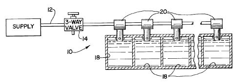
FIGURE 1 is a schematic view illustrating the general
arrangement of the system of the present invention as used to
service a plurality of containers.
FIGURE 2 is also a schematic view serving to illustrate the
general arrangement of the system of the components which make up
the container filling device of the present invention.
FIGURE 3 is an enlarged side cross-sectional view of the
refill valve apparatus described in U.S. Patent No. 5,090,442.
Description of the Preferred Embodiment
Referring to the drawings, and particularly FIGURES 1 and 2,
a container filling system and apparatus are illustrated. The
system is designated generally as 10 and includes a liquid supply
conduit 12 connected to a source of liquid under pressure, a liquid
supply valve 14, and a plurality of container filling means 20,
each servicing an individual container 18. Each filling means 20
is connected to conduit Z2 via tap line 16 and includes a main
valve means 30, a fluid amplifier means 70 and pilot valve means
80.
8
CA 02098979 2003-09-30
Conduit 12 provides an unobstructed flow passageway fronn
valve 14 to each of the filling means 20 which operate to fill -
their respective containers independently of one another.
Preferably, valve 14 is of a three-way design to permit opening or
closing the system to the pressurized liquid supply or venting the
system to atmosphere. The valve 14 may be manually or
automatically operated and may be positioned, as shown in FIGURE
1, at a remote location from the containers 18. Alternatively,
separate valves may be employed in the tap lines 16 to actuate
each filling means 20 separately.
With reference to FIGURE 3, which as noted previously
compares to the refill apparatus shown in U.S. patent 5,090,442,
(FIGURE 2), the container filling means 20 is shown more
particularly in relation to a container in the form of a battery
55 and battery cover 56, is provided for filling the battery to a
predetermined level and includes a lower valve housing 40, an
upper cap housing 50 and a swivel connector 90. The swivel
connector 90 allows the filling means maintain fluid communication
between an external supply means and the container 18 in the form
of battery 56. Supply lines 57 enable fluid communication between
swivel connector 90 and battery cover 56 and thus battery 55 (the
connection to battery 55 not shown). Bayonet threads 58 on upper
cap housing 50 cooperate with a corresponding recess within
battery cover 56, allowing the connection of container filling
means 20 to battery 55.
The lower valve housing 40 includes snap tab 41, which
releasably engages a recess 51 within upper cap housing 50. The
upper portion of lower valve housing 40 is formed by main valve
9
CA 02098979 2003-09-30
seat 44, which is rigidly connected to the upper peripheral
portions of the lower valve housing 40, preferably by ultrasonic
welding techniques, to form a leak-tight seal which securely holds
the valve components in position. The joints which are ultrasonic
welded are indicated by thickened lines 46. The main valve seat
44 includes a weld area adjacent to the upper periphery of lower
valve housing 40 sufficient to withstand the operating pressures
acting on the lower surface 44' of seat 44. Finally, a boss 62 on
upper cap housing 50 is insertable into a corresponding recess 48
within main valve seat 44 on valve housing 40, ensuring a sure and
snap-fit connection and a leak-tight joint. The boss 62 fits
within recess 48 on the valve seat with a light press fit that
assures a sealing connection while allowing the valve housing to
be easily assembled and disassembled thereto.
Due to the rigid connection between lower valve housing 40
and main valve seat 44 at ultrasonic welds 46, the valve operating
pressure only acts over the smaller boss 62 diameter. Therefore,
the operating pressure acting to separate upper cap housing 50
from lower valve housing 40 is applied only between boss 62 and
recess 48 on valve seat 44. Since the valve operating pressure
remains constant but acts over a smaller area, the force acting to
separate valve housing 40 from cap housing 50 is relatively small
and can be overcome by the simple tab and accommodating recess
arrangement described above.
With the filling means as shown, field replacement is easily
accomplished. Tab 41 is simply depressed from recess 51 and valve
housing 40, which acts as the male plug and contains the valve
components, is pulled out from cap housing 50, which acts as the
female receptacle. A new component and the old, non-damaged
9A
CA 02098979 2003-09-30
component are then snapped back together.
The fluid amplifier means 70 and pilot valve means 80,
disclosed by U.S. patent No. 4,527,593 and shown in FIGURE 3, are
also readily adaptable to the main valve 30.
The preferred embodiment of the present invention incorpo-
rates TPE tubing within a battery watering system for the inter-
connection of individual battery cells throughout the watering
system. PVC tubing may still be used to connect the main supply
valve to a water supply such as a reservoir, since it has been
found that tactification within the tubing does not occur down-
stream of the main valve. The particularly preferred embodiment
of the present invention incorporates a TPE known as NORPRENE~ made
by Norton Company, which is made from a TPE known as SANTOPRENE~.
SANTOPRENE~ is a polyolefin TPE with a unique combination of
environmental resistance (due to the presence of general purpose
EPDM rubber) and fluid resistance (due to the presence of general
purpose polychloroprene rubber). The fully vulcanized rubber
particles of NORPRENE~ are dispersed throughout a continuous matrix
9B
vs;~ a~
~,~ a;
of polyolefinic thermoplastic. NORPRENE~ is economical to
manufacture since it can be produced on normal thermoplastic
processing equipment, and its tubing scrap can be recycled, further
contributing to its economy in use.
Another embodiment of the present invention which meets the
required performance characteristics incorporates tubing made from
fluorocarbons or fluorelastomers. VITON~, manufactured by E.I.
DuPont De Nemours Company, is one such tubing material that has
been determined to be suitable from a performance standpoint.
However, while tubing made from materials in this category offers
physical, environmental and chemical properties which make such
tubing functionally desirable, it is presently too expensive for
general use in battery watering systems.
Yet another embodiment of the present invention which meets
the required performance characteristics specified above
incorporates tubing made from fluoropolymers, including the
polymers known in the trade as PTFE, FEP, and PFA. ~, typical such
polymer is DuPont's TEFLbN~. Another is CHEMFLUOR~, made by
Chemplast, Inc. of New Jersey. However, these types of tubing are
presently very expensive and their use is typically conf fined to
food, medical and semiconductor processing applications.
It should be understood that various changes and modifications
to the illustrated preferred embodiment will be apparent to those
skilled in the art. Such changes and modifications can be made
without departing from the spirit and scope of the present
invention and without diminishing its intended advantages. It is,
therefore, intended that such changes and modifications be covered
by the following claims.
11