Language selection

Search

Patent 2099386 Summary

Third-party information liability

Some of the information on this Web page has been provided by external sources. The Government of Canada is not responsible for the accuracy, reliability or currency of the information supplied by external sources. Users wishing to rely upon this information should consult directly with the source of the information. Content provided by external sources is not subject to official languages, privacy and accessibility requirements.

Claims and Abstract availability

Any discrepancies in the text and image of the Claims and Abstract are due to differing posting times. Text of the Claims and Abstract are posted:

  • At the time the application is open to public inspection;
  • At the time of issue of the patent (grant).
(12) Patent: (11) CA 2099386
(54) English Title: ARMATURE ASSEMBLY FOR ELECTROMAGNETIC DOOR HOLDER
(54) French Title: FERRURES POUR DISPOSITIF ELECTROMAGNETIQUE DE RETENUE DE PORTE
Status: Deemed expired
Bibliographic Data
(51) International Patent Classification (IPC):
  • E05C 17/56 (2006.01)
(72) Inventors :
  • ZIMMERMAN, MICHAEL (United States of America)
  • NEW, MARK A. (United States of America)
(73) Owners :
  • VON DUPRIN, INC. (United States of America)
(71) Applicants :
(74) Agent: NORTON ROSE FULBRIGHT CANADA LLP/S.E.N.C.R.L., S.R.L.
(74) Associate agent:
(45) Issued: 1997-09-23
(86) PCT Filing Date: 1992-07-27
(87) Open to Public Inspection: 1993-05-09
Examination requested: 1993-06-28
Availability of licence: N/A
(25) Language of filing: English

Patent Cooperation Treaty (PCT): Yes
(86) PCT Filing Number: PCT/US1992/006196
(87) International Publication Number: WO1993/009320
(85) National Entry: 1993-06-28

(30) Application Priority Data:
Application No. Country/Territory Date
789,564 United States of America 1991-11-08

Abstracts

English Abstract


An armature assembly for use with an electromagnetic
door holder has a ball stud (10) pivotably connected at one
end of a mounting bracket (30) and at the other end to an
armature plate (40). The mounting bracket (30) is mounted on a
first structural member, a mounting body (35) is secured to the
bracket and connects with the ball stud, and the armature
plate (40) coacts with and is held against an electromagnet
which is mounted on a second structural member. The pivotable
attachments at both ends of the ball stud provide an almost
universal adjustability to the armature assembly and,
thus, accommodate complex misalignments between the first
and second structural surfaces.


French Abstract

rmature pour utilisation avec un système de retenue de porte électromagnétique comprenant une queue de rotule hémisphérique (10) connectée de manière à pivoter à l'une des extrémités d'un support de fixation (30) et à l'autre extrémité, à une plaque d'armature (40). Le support de fixation (30) est assemblé sur un premier élément structural, un corps d'assemblage (35) est fixé à la fixation et est relié à la queue de rotule hémisphérique, et la plaque d'armature (40) agit de concert avec un électro-aimant fixé à un deuxième élément structural et est retenue contre l'électro-aimant. Les accessoires pivotants aux deux extrémités de la queue de rotule hémisphérique procurent un ajustement presque universel à l'armature et, par conséquent, s'adaptent aux désalignements complexes entre les première et deuxième surfaces structurales.

Claims

Note: Claims are shown in the official language in which they were submitted.


What is claimed is:

1. An armature assembly, for use with an electromagnetic door holder, said
armature assembly of the type having a mounting bracket and an armature plate means
for coacting with an electromagnet, the improvement comprising.
said mounting bracket being mounted on a first structural member and ball stud
means which has a first end pivotably connected to said mounting bracket and which
is pivotable about at least two axes; and
said armature plate means being pivotably connected with a second end of said
ball stud means.

2. The armature assembly of claim 1, wherein the ball stud means
comprises a ball means at one of said first and second ends for pivotably connecting
with a socket on said mounting bracket body and a clevis means at the other of said
first and second ends for pivotably connecting with a drilled stud on said armature
plate means.

3. The armature assembly of claim 1, wherein the ball stud means
comprises a ball means at each of said first and second ends.

4. The armature assembly of claim 1, wherein the ball stud means
comprises a ball means at one of said first and second ends and a transversely drilled
stud means at the other of said first and second ends for pivotably connecting with a
clevis means on said armature plate means.

5. The armature assembly of claim 1, wherein the first structural member
is a movable door and the armature plate means coacts with said electromagnet which
is mounted on a second structural member being a stationary wall of a passageway.


6. The armature assembly of claim 1, wherein the first structural member
is a movable door and the armature plate means coacts with said electromagnet which
is mounted on a second structural member being a movable door.

7. The armature assembly of claim 1, wherein the ball stud means
comprises a ball means at one of said first and second ends and a transversely drilled
stud means at the other of said first and second ends for pivotably connecting with a
rotatable clevis means on said mounting bracket.

8. The armature assembly of claim 1, wherein the ball stud means
comprises a ball means at one of said first and second ends and a clevis means at the
other of said first and second ends for pivotably connecting with a rotatable
transversely drilled stud means on said mounting bracket.

9. An armature assembly, for use with an electromagnetic door holder,
comprising:
a substantially circular mounting bracket plate mounted on a first structural
member and having a plurality of axially offset radially outwardly extending tabs about
a circumferential edge;
a mounting body having a substantially circular cavity and a plurality of
radially inwardly extending tab means for engaging with the tabs of said mounting
bracket plate to clamp said mounting body to said mounting bracket plate; and
an armature plate means for coacting with an electromagnet mounted on a
second structural member, said armature plate means being pivotably and articulably
connected to said mounting body by a ball stud means.

10. The armature assembly of claim 9, wherein said mounting bracket plate is
first fastened to said first structural member, and the mounting body, incorporating the
ball of said ball stud means and a biasing socket means, is placed over and forced
axially toward said mounting bracket plate against said biasing socket means and


rotated to engage the tab means of said mounting body with the tabs of said mounting
bracket plate.

Description

Note: Descriptions are shown in the official language in which they were submitted.


W093~09320 1 2 0 9 9 3 81~ Pcr/usg2/06l96

AR~TURE ASSEMBLY FOR ELECTROMAGNETIC DOOR HOLDE~
BA~KGROUNI) OF THE ]NVENT10~

7his invention relates ~enerallv to electroma~netic door holders and more
particularlv to armature assemblies ~or use wi~h electroma~netic door holders.

, _
Electroma~netic door holders are commonl~ used to hold fire doors open in
hospitals. schools, hotels~ and other bl-ildin~s havin~ corridors where fire doors are
present and traffic is heav~. The electroma~llet is normallv wired into the fire ala~n
svstem or other emer~ency svstem for the building. When a fire is detected. the fir~
alarm or other emergency system will cause an interruption of power to the
elc.;~l("~ net. This will allow every electroma~netical~v held door to be released and
to close~ ~Lherebv containin~ the fire.

Since electroma~netic a~ractive force is proportional tO contact area. it is clear
that anvthill~ which reduces the area of contact between the elecllollla~net and the
~rm~tl~re~ will rapidly reduce the magnetic holding force. This can lead tO !~nintended
closir~g of fire doors which condition could ~teate a ha~ard dunng eJ,Iel~.cncv
e~-l and parallelism between the ele~,llvllla~net and the armature
plate are~ ~herefore, important to the stren~th of the electroma~net~armature ~rip.

l~is~ nment and out of par~lleli~nl can be caused by stmctural S~in~
y~ pC~ .n~lchin~ of s~n~lorr .I;~ c~ be~ween the door hinges and the electroma~net
assembly, and defe~ts in workm~n~hir durin~ ~o~ hlg of the doors, the
el~lv,.~net, and the ~rm~tU~e plates. Re~ardless of the cause~ the we~k~nin~ effect
of non-parallel ~ontact is the same~ and attempts have been made to provide for
adjustabilitv to overcome the non parallel condition. Most of these attempts ha~e
pc~ ed adjustment of parallelism~ but ha~e failed to provide for ali~nment to assure
complete face to face contact between the electroma~net ard the arntature.
;


z
~:

'W~ 93~09320 PCr/lJS92/~6196
20 99:~86 ~s~

The foregoing illustra~es limitations known to exist in present devices and
methods. Thus, it is apparent that it would be advantageous to provide an alternative
directed to overcoming one or more of the limitations set forth above. Accordingly, a
suitable alternative is provided including features more ~lly discl~sed. hereina~er.
, .
SUMMARY OF THE lNVENllON

In one aspect of the present invention, this is accomplished by providing an
armature assembly, for use with an electromagnetic door holder, having a mounting
body pivotab~y connected with a first end of a ball stud and mounted on a first
structural member; and an annature plate for coacting with an electromagnet mounted
on a second structural member, the armature plate being pivotably connected with a
second end of the ball stud.

; The foregoing and other aspects will become apparent from tl~e following
detailed description of thê invention when considered in conjunction with the
acco".~ ying draw~ng figures.

BRIEF DESCRIPTION OF THE DRAWXNGS

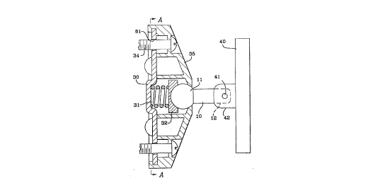
Figure 1 shows the ma~tic door holder ~ h1re assembly of tbe present
invention in partial section to illustrate details of its construction;

Figu~ is a view from line A-A of Figure 1 illustrating the preferred
arrangernent ~or conrlecting the mounting body to the mounting bracket plate;
~ !

Figures 2 and 2A show elevation and plan views, respectively, of the magnetic
door holder armature of the present invention coupled with an electrom~Z~net;


.
- ~. , . .. , ~ .. . ..

Wo 93/0932û 2 0 9 9 ~ 8 6 Pcr/U~92/06~96

~,.

-~ Figures 3, 4, and 5 show the electromagnetic a~nature assembly of the present
. invention in its preferred embodiment, and in two alterna~ive embodiments,
respectively; and

Figures 6 and 7 show partially sectional views of alternative embodiments of
the present invention having the ball end of the ball stud connected to the arrnature
plate instead of the mounting body.
:,
' DETAILED DESCRIPTION

The magnetic door holder a~ature assembly of the present inven~ion is shown
in Figure 1. The armature mounting body 35 is preferably mounted to a cloor or
movable structure using mounting bracket 30 which is secured by fasteners 34 through
holes 81. Within mounting body 35 can be seen ball 11, socket cup 32, and spring 31
which is co,~ essed between socket cup 32 and mounting bracket 30 to provide a
biasing socket. Ball 11 is shown as one end of ball stud 10 which projects outwardly
. from body 35 and ends as a transversely drilled stud 12 at its other extremity.
Armature plate 40 is articulably joined to ball stud 10 by means of pin 41 extending
through transversely drilled stud 12 and clevis 42 which is pelmanently fixed tot-lre plate 40. Consideration of this figure shows that ~rrn~tlJre plate 40 is free to
articulate about pin 41 by means of clevis 42. At the same time, ball stud 10 can be
ar~icul~te~l in any direction and can also be rotated about its lon~ihldin~l axis. This
combina~ion of movement a~ilities permits the armature assembly to ac~ommodate
virtually any mis$llignment condition in any direction.

. .............. .
Figure 1A shows the preferred method of att~çhing mounting body 35 to
mounting bracket plate 30. Mounting bracket plate 30 is fastened to a structuralmember using fasteners (not shcwn) in fastener hol~s 81. Moun~ing body 35 is then
placed over mounting bracket plate 30 such that mounting body tabs 83 and mounting
bracket tabs 82 are interdigitated. Body 35 is forced inward to compress spring 31
~;
.~;
.

WO 93/093~0 2 0 9 9 3 8 6 PCr/US92tO61~6

.


(Figure 1) and is rs~tated to engage tabs 83 and 82, as illustrated. Bias of spring 31
retains tabs in engagement and provides frictional clamping of ball 11 (Figure 1) of
ball stud 10.

ln its preferred embodiment, the magnetic door holder armature assembly is
mounted to the door or movable structure, while the mating electromagnet is mounted
to the wall or stationary structure. This arrangement, however, may be reversed if
conditions so require.

Figwres 2 and 2A present elevation and plan views, respectively, of the
~rrnAtllre assembly of the present invention in use with a mi~ ned çlectromagnet.
These figures illustrate the accommodation of combined vertical and horizontal
mi~ nment by the ~rmfl~llre assembly of the presen~ invention. These views
illustrate compensation by the arm~t~re assembly for both Y axis and Z axis
mi~ nment. l~his is made possible by the articuIation provided by clevis 42 atld pin
41, together with the universal flexibility and the rotatability of body 35 about ball
stud 10.

Figures 3 to 5 present two alternative embodiments of the ~rm~ture assembly of
the present invention. Figure 3 shows the inYention in its preferred embodiment with
the exception that, in this case~ 2nn~ture mount body 3~ is mounted to the wall or
st~tion~ry structure 7. In all other respects, the embodiment of Figure 3 is the same as
that showll in Figures 1 and 2.

The ~ tllre assembly of Figure 4 is very similar to the prefelrcd embodiment,
except that, in this case, ~nn~tl1re plate 150 has a permanently attached protruding
cross drilled stud 153 which couples by pin 154 to clevis 72. Clevis 72 is part of ball
stud 70, the other end of which couples to mounting body 35. Figure S presents
ano~er embodiment. Ball stud 60 is equipped with a ball 61 at each end. In this


,

wo g3/09320 2 0 9 9 3 8 6 PCr/US9~/06196

.

case, armature plate 140~ as well as mounting body 35, is adapted to coupie to ball 61
on ball stud 60.
'
As seen in Figures 6 and 7, it is also possible to achieve the, same universal
- adjustability with the clevis 137 or cross drilled stud 133 situated on the mounting
body 135. In this embodiment, clevis 137 or stud 133 is rotatable about its axis at its
att~(~.hment to mounting body 135. Here, also, mounting body 135 is attached directly
to structural member 5 using fasteners 136 through body 135.
;


Note that, in all Figures, there is universal flexibility of the ball stud with
respect to the structurally mounted mounting bracket body. This is provided by the
ball end of the ball stud in Figures 1-5 and by the clevis/cross drilled stud in~j combination with the axially rotatable member 137, 133 in Figures 6 and 7. lhîs
allows adjustment of the ~ ture plate in a 360~ arc about the axis of the moun~ing
bracket body while perrnittin~ the armature plate to remain parallel to the body or to
be tilted to maintain full contact with the electromagnet.

All of these embodiments provide the same universal adjustability required to
accommodate combinations of mi~ nments. lt is preferred that armature plates andele~ a~ets have circlllar shapes, so that there is no requirement for radial
si ol;Gl~laiion, or l'clock"~ between the ~nn~t~lre and the electrorn~net.


.i
.!.' ~
' ~ :


,?

. ~

' _

r
' :'

J r
~iS,

Representative Drawing
A single figure which represents the drawing illustrating the invention.
Administrative Status

For a clearer understanding of the status of the application/patent presented on this page, the site Disclaimer , as well as the definitions for Patent , Administrative Status , Maintenance Fee  and Payment History  should be consulted.

Administrative Status

Title Date
Forecasted Issue Date 1997-09-23
(86) PCT Filing Date 1992-07-27
(87) PCT Publication Date 1993-05-09
(85) National Entry 1993-06-28
Examination Requested 1993-06-28
(45) Issued 1997-09-23
Deemed Expired 2004-07-27

Abandonment History

There is no abandonment history.

Payment History

Fee Type Anniversary Year Due Date Amount Paid Paid Date
Application Fee $0.00 1993-06-28
Registration of a document - section 124 $0.00 1994-05-13
Maintenance Fee - Application - New Act 2 1994-07-27 $100.00 1994-07-04
Maintenance Fee - Application - New Act 3 1995-07-27 $100.00 1995-06-29
Maintenance Fee - Application - New Act 4 1996-07-29 $100.00 1996-06-28
Final Fee $300.00 1997-04-14
Maintenance Fee - Application - New Act 5 1997-07-28 $150.00 1997-07-10
Maintenance Fee - Patent - New Act 6 1998-07-27 $150.00 1998-07-08
Maintenance Fee - Patent - New Act 7 1999-07-27 $150.00 1999-07-02
Maintenance Fee - Patent - New Act 8 2000-07-27 $150.00 2000-07-04
Maintenance Fee - Patent - New Act 9 2001-07-27 $150.00 2001-07-03
Maintenance Fee - Patent - New Act 10 2002-07-29 $200.00 2002-07-03
Owners on Record

Note: Records showing the ownership history in alphabetical order.

Current Owners on Record
VON DUPRIN, INC.
Past Owners on Record
NEW, MARK A.
ZIMMERMAN, MICHAEL
Past Owners that do not appear in the "Owners on Record" listing will appear in other documentation within the application.
Documents

To view selected files, please enter reCAPTCHA code :


To view images, click a link in the Document Description column. To download the documents, select one or more checkboxes in the first column and then click the "Download Selected in PDF format (Zip Archive)" or the "Download Selected as Single PDF" button.

List of published and non-published patent-specific documents on the CPD .

If you have any difficulty accessing content, you can call the Client Service Centre at 1-866-997-1936 or send them an e-mail at CIPO Client Service Centre.


Document
Description 
Date
(yyyy-mm-dd) 
Number of pages   Size of Image (KB) 
Claims 1996-11-12 3 84
Cover Page 1995-08-19 1 21
Abstract 1995-08-19 1 63
Claims 1995-08-19 3 114
Drawings 1995-08-19 5 129
Cover Page 1997-09-02 1 51
Description 1995-08-19 5 267
Representative Drawing 1997-09-02 1 9
Prosecution Correspondence 1993-06-28 1 32
International Preliminary Examination Report 1993-06-28 4 107
PCT Correspondence 1997-04-14 1 43
PCT Correspondence 1993-12-22 1 45
Office Letter 1993-09-24 2 40
Office Letter 1993-12-15 1 63
Fees 1996-06-28 1 58
Fees 1995-06-29 1 60
Fees 1994-07-04 1 65