Note: Descriptions are shown in the official language in which they were submitted.
98-3921
BICYCLE SEAT POST ALARM
SPECIFICATION:
What makes the Bicycle Seat Post Alarm unique is
that no one can tamper with it because all of the
components are contained in the seat post. For example,
no one can cut the battery or buzzer wires. See Figure
1.
The Bicycle Seat Post Alarm is a very basic and
simple alarm circuit to put together. The Bicycle Seat
Post Alarm detects anyone tilting or shaking the
bicycle. Preferably, it consists of 4 "AAA" batteries,
two mercury tilt switches, one mini 5 volt DPDT (double
pole, double throw) relay, one SPDT (single pole, single
throw) key switch, 1/8 phono jack and a mini buzzer.
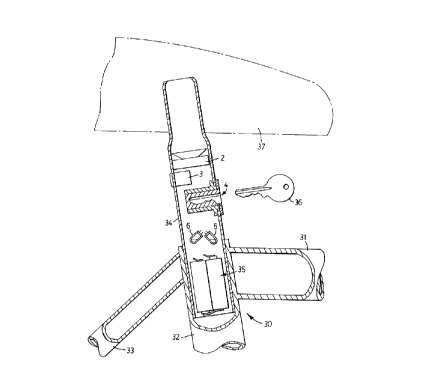
Figure One shows a block style diagram of the
Bicycle Seat Post Alarm.
Figure Two shows a schematic diagram of the Bicycle
Seat Post Alarm.
With reference to Figure 1, bicycle seat post 34 is
shown inserted in seat tube 32 of bicycle frame 30
(partially shown with cross bar 31 and seat stay 33).
Bicycle seat 37, shown in phantom outline, is attached
to the top of bicycle seat post 34 by means (not shown).
A few key components of the bicycle seat post alarm are
shown in Figure 1, i.e. tilt switches 5 and 6, key
switch 4, alarm buzzer 2, batteries 35 and phono jack 3.
The electrical connections between these key components
and other components are omitted from Figure 1 for
simplicity of understanding the invention. Key 36 is
used to operate key switch 4, as shown in Figure 1. The
electrical connections are shown, however, in Figure 2.
With reference to Figure Two, the Bicycle Seat Post
Alarm is a basic latching relay circuit. There are two
mercury tilt switches indicated by numbers 5 and 6, they
are connected together in parallel through lead wires
number 16 and 17.
These tilt switches 5 and 6 are positioned in a way
that they can detect movement in either direction e.g.
,c
20993gg
- 2 -
tilting the bicycle.
There is an on/off switch SPDT (single pole, double
throw) key switch in the circuit indicated by number 4,
its common terminal is connected to the positive
terminal of the battery by lead wire number 19. When
the switch indicated by number 4 is in the NC (normally
closed) position, it gives power to the circuit through
lead wire number 18 which is connected from the NC
(normally closed) terminal of switch number 4 to one
terminal of the tilt switch number 6. When either of
the two switches number 5 or 6 contacts close by
movement, relay 1 is energized through lead wire 13.
Lead wire 13 is connected from the other terminal of the
tilt switch number 6 to the positive terminal of relay
1. Lead wire number 12 is connected from the negative
terminal of the relay l, to the negative terminal of the
battery.
Once Relay 1 has energized, the contacts will
change state. Lead wire 14 is connected to the common
terminal of relay 1 indicated by number 20. The voltage
in lead wire 14 is a constant 6 volts which is connected
to the NC (normally closed)terminal of switch number 4.
Relay 1 stays latched by lead wire number 15 which is
connected to lead wire 13 and to the NO (normally open)
contacts indicated by number 21 of the Relay number 1.
The buzzer is sounded by using the other sets of
contacts of relay 1. Lead wire number 7 is connected to
the NO (normally open) contact indicated by number 23 of
relay 1 and to the positive terminal of the buzzer
number 2.
Lead wire number 8 is connected directly to the
negative terminal of the battery and to the negative
terminal of buzzer number 2. Lead wire number 11 is
connected from the NC (normally closed) terminal of
switch number 4, to the common terminal of Relay 1
indicated by number 22. The buzzer will sound until
power is interrupted from the circuit. This is done by
c
.2099395
- 3 -
switch number 4, when it changes state, power is
disconnected to relay number 1.
All of the above mentioned components and wires are
installed in a standard size seat post.
To summarize the way that the Bicycle Seat Post
Alarm circuit works, when switch number 4 is in the NC
(normally closed) position it is on, meaning that if the
tilt switches detect movement, it will energize the
relay and sound the buzzer. The buzzer will sound until
switch number 4 is turned off.
The Bicycle Seat Post Alarm also has a panic
feature. This is done through lead wire number 10 and
9. Lead wire number 10 is connected to the NO (normally
open) terminal of switch number 4 and to the common
terminal of the phono jack number 3. Lead wire number 9
is connected to the positive terminal of buzzer number 2
and the NC (normally closed) terminal of the phono jack
number 3. When the phono jack number 3 has a plug in
it, the contacts remain open. When the plug is removed
the contacts close and will sound the buzzer.
Switch number 4 controls whether you want the alarm
on for the bicycle or whether you want the panic alarm
while you are riding your bicycle. When switch number 4
is in the NC (normally closed) position, it gives power
only for the bicycle alarm and not the panic feature, it
is connected this way so that when the rider parks
his/her bicycle, they can turn on the alarm for the
bicycle and remove the panic plug so that no one takes
it.
If the rider wants to ride his/her bicycle, all
they have to do is make sure that the panic plug is in
place and then change the state of switch number 4 from
NC (normally closed) to NO (normally open), when this is
done, the panic circuit is enabled. If the rider feels
that he/she is in danger, they can just pull out the
plug from the Bicycle Seat Post Alarm and it will sound
the buzzer to draw attention. If the rider wants to
.2099395
- 4 -
stop the buzzer he/she must re-insert the plug into the
phono jack which is mounted on the Bicycle Seat Post
alarm.
It will be understood that the alarm system of the
present invention is easy to install and can be
transferred easily to another bicycle. Furthermore, it
is easy to replace the battery or batteries.
C