Language selection

Search

Patent 2099469 Summary

Third-party information liability

Some of the information on this Web page has been provided by external sources. The Government of Canada is not responsible for the accuracy, reliability or currency of the information supplied by external sources. Users wishing to rely upon this information should consult directly with the source of the information. Content provided by external sources is not subject to official languages, privacy and accessibility requirements.

Claims and Abstract availability

Any discrepancies in the text and image of the Claims and Abstract are due to differing posting times. Text of the Claims and Abstract are posted:

  • At the time the application is open to public inspection;
  • At the time of issue of the patent (grant).
(12) Patent: (11) CA 2099469
(54) English Title: HYDRAULIC PRESSURE TRANSFORMER
(54) French Title: MULTIPLICATEUR DE PRESSION HYDRAULIQUE
Status: Deemed expired
Bibliographic Data
(51) International Patent Classification (IPC):
  • F15B 3/00 (2006.01)
  • F15B 11/032 (2006.01)
  • F15B 15/20 (2006.01)
(72) Inventors :
  • MALINA, VIKTOR (Germany)
(73) Owners :
  • TOX PRESSOTECHNIK GMBH (Germany)
(71) Applicants :
  • TOX PRESSOTECHNIK GMBH (Germany)
(74) Agent: ROBIC
(74) Associate agent:
(45) Issued: 1999-09-21
(22) Filed Date: 1993-06-30
(41) Open to Public Inspection: 1994-01-03
Examination requested: 1995-12-12
Availability of licence: N/A
(25) Language of filing: English

Patent Cooperation Treaty (PCT): No

(30) Application Priority Data:
Application No. Country/Territory Date
P42 21 638.9 Germany 1992-07-02

Abstracts

English Abstract


The invention relates to a hydraulic pressure
transformer, wherein a storage chamber and a work chamber
are connected with each other via an overflow bore into
which a plunger piston dips to generate a pressure stage
and thereby separates the two chambers for generating a
high pressure in the work chamber. An additional
connecting conduit with a check valve is provided between
the work chamber and the storage chamber.


Claims

Note: Claims are shown in the official language in which they were submitted.


9
WHAT IS CLAIMED IS
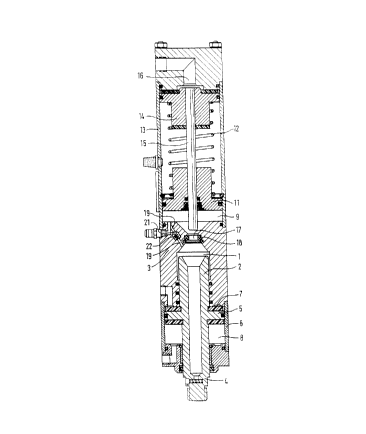
1. A hydraulic pressure transformer including:
a housing (3),
a work chamber (1) in said housing, which is filled with
a hydraulic fluid during operation,
a work piston (2) operates in said housing in
conjunction with said work chamber,
a piston rod (4) is connected with said work piston and
extends outside of the housing (1),
a storage chamber (9) which is filled with a hydraulic
fluid during operation, a bore (17) of a defined cross
section provides a connection which hydraulically
connects said storage chamber (9) with said work chamber
(1) ,
a casing (13) which is secured to said housing (3),
a drive piston (14) operable in said casing,
a plunger piston (15) secured to said drive piston,
said plunger piston (15) being of a smaller diameter
than that of the work piston (2), said plunger piston
being forced under low pressure in the work chamber in a
radially sealing manner into the bore (17), while a flow
of hydraulic fluid out of the storage chamber (9) into
the work chamber (1) takes place, and said plunger
piston returns out of the bore (17), generating a
corresponding high pressure in the work chamber (1), so
that the hydraulic fluid can flow from the work chamber
(1) back into the storage chamber, characterized in
that:
a connecting conduit (19, 23) is disposed between the work
chamber (1) and storage chamber (9) in addition to the
connection containing the bore (17), said connecting conduit


10
being blocked against fluid flow back to said storage chamber
when high pressure begins in said work chamber and is opened
at low pressure in said work chamber in a direction of fluid
flow towards the work chamber (1).
2. A hydraulic pressure transformer in accordance with
claim 1, in which a one-way check valve (21, 22, 24, 25) is
disposed in the connecting conduit (19, 23), which opens in a
direction toward the work chamber (1) and closes in a
direction toward the storage chamber (9).
3. A hydraulic pressure transformer in accordance with
claim 2, in which the movable valve member (21, 24) of the
check valve is loaded by means of a spring (22, 25).
4. A hydraulic pressure transformer in accordance with
claim 1, in which the connecting conduit (19) extends inside
the housing (3).
5. A hydraulic pressure transformer in accordance with
claim 2, in which the connecting conduit (19) extends inside
the housing (3).
6. A hydraulic pressure transformer in accordance with
claim 3, in which the connecting conduit (19) extends inside
the housing (3).
7. A hydraulic pressure transformer in accordance with
claim 1, in which the connecting conduit is formed by a line
(23) extending outside of the housing and between said work
chamber (1) and said storage chamber (9).
8. A hydraulic pressure transformer in accordance with
claim 2, in which the connecting conduit is formed by a line


11
(23) extending outside of the housing and between said work
chamber (1) and said storage chamber (9).
9. A hydraulic pressure transformer in accordance with
claim 3, in which the connecting conduit is formed by a line
(23) extending outside of the housing and between said work
chamber (1) and said storage chamber (9).
10. A hydraulic pressure transformer in accordance with
claim 4, in which the connecting conduit is formed by a line
(23) extending outside of the housing and between said work
chamber (1) and said storage chamber (9).
11. A hydraulic pressure transformer in accordance with
claim 5, in which the connecting conduit is formed by a line
(23) extending outside of the housing and between said work
chamber (1) and said storage chamber (9).
12. A hydraulic pressure transformer in accordance with
claim 6, in which the connecting conduit is formed by a line
(23) extending outside of the housing and between said work
chamber (1) and said storage chamber (9).
13. A hydraulic pressure transformer in accordance with
claim 1, in which:
said work piston (2), said work chamber (1), said bore
(17), said storage chamber (9) and said plunger piston
(15) are disposed on a same axis,
means for actuation of the drive piston (14) and the
plunger piston (15) counter to a restoring force (12),
said bore (17) is in a transverse wall between the work
chamber (1) and the storage chamber (9) and a lip seal
(18) suitable for high pressure is disposed in the bore
(17).


12
a storage piston (11), which provides a storage
pressure, is operatively loaded for axial displacement
and includes radially sealing, said storage piston
separates the storage chamber (9) from a chamber filled
with air; and
an auxiliary piston (5) is formed by a ring piston
integral with the work piston (2), said auxiliary piston
(5) can be charged with pressure alternately on either
side for producing rapid strokes of said work piston.
14. A hydraulic pressure transformer in accordance with
claim 2, in which:
said work piston (2), said work chamber (1), said bore
(17), said storage chamber (9) and said plunger piston
(15) are disposed on a same axis,
means for actuation of the drive piston (14) and the
plunger piston (15) counter to a restoring force (12),
said bore (17) is in a transverse wall between the work
chamber (1) and the storage chamber (9) and a lip seal
(18) suitable for high pressure is disposed in the bore
(17).
a storage piston (11), which provides a storage
pressure, is operatively loaded for axial displacement
and includes radially sealing, said storage piston
separates the storage chamber (9) from a chamber filled
with air; and
an auxiliary piston (5) is formed by a ring piston
integral with the work piston (2), said auxiliary piston
(5) can be charged with pressure alternately on either
side for producing rapid strokes of said work piston.
15. A hydraulic pressure transformer in accordance with
claim 3, in which:


13
said work piston (2), said work chamber (1), said bore
(17), said storage chamber (9) and said plunger piston
(15) are disposed on a same axis,
means for actuation of the drive piston (14) and the
plunger piston (15) counter to a restoring force (12),
said bore (17) is in a transverse wall between the work
chamber (1) and the storage chamber (9) and a lip seal
(18) suitable for high pressure is disposed in the bore
(17),
a storage piston (11), which provides a storage
pressure, is operatively loaded for axial displacement
and includes radially sealing, said storage piston
separates the storage chamber (9) from a chamber filled
with air; and
an auxiliary piston (5) is formed by a ring piston
integral with the work piston (2), said auxiliary piston
(5) can be charged with pressure alternately on either
side for producing rapid strokes of said work piston.
6. A hydraulic pressure transformer in accordance with
claim 4, in which:
said work piston (2), said work chamber (1), said bore
(17), said storage chamber (9) and said plunger piston
(15) are disposed on a same axis,
means for actuation of the drive piston (14) and the
plunger piston (15) counter to a restoring force (12),


14
said bore (17) is in a transverse wall between the
work chamber (1) and the storage chamber (9) and a lip
seal (18) suitable for high pressure is disposed in the
bore (17),
a storage piston (11), which provides a storage
pressure, is operatively loaded for axial displacement
and includes radially sealing, said storage piston
separates the storage chamber (9) from a chamber filled
with air; and
an auxiliary piston (5) is formed by a ring piston
integral with the work piston (2), said auxiliary piston
(5) can be charged with pressure alternately on either
side for producing rapid strokes of said work piston.
17. A hydraulic pressure transformer in accordance with
claim 5, in which
said work piston (2), said work chamber (1), said
bore (17), said storage chamber (9) and said plunger
piston (15) are disposed on a same axis,
means for actuation of the drive piston (14) and the
plunger piston (15) counter to a restoring force (12),
said bore (17) is in a transverse wall between the
work chamber (1) and the storage chamber (9) and a lip
seal (18) suitable for high pressure is disposed in the
bore (17),
a storage piston (11), which provides a storage
pressure, is operatively loaded for axial displacement
and includes radially sealing, said storage piston
separates the storage chamber (9) from a chamber filled
with airy and
an auxiliary piston (5) is formed by a ring piston
integral with the work piston (2), said auxiliary piston
(5) can be charged with pressure alternately on either
side for producing rapid strokes of said work piston.
18. A hydraulic pressure transformer in accordance with
claim 6, in which


15


said work piston (2), said work chamber (1), said
bore (17), said storage chamber (9) and said plunger
piston (15) are disposed on a same axis,
means for actuation of the drive piston (14) and the
plunger piston (15) counter to a restoring force (12),
said bore (17) is in a transverse wall between the
work chamber (1) and the storage chamber (9) and a lip
seal (18) suitable for high pressure is disposed in the
bore (17),
a storage piston (11), which provides a storage
pressure, is operatively loaded for axial displacement
and includes radially sealing, said storage piston
separates the storage chamber (9) from a chamber filled
with air; and
an auxiliary piston (5) is formed by a ring piston
integral with the work piston (2), said auxiliary piston
(5) can be charged with pressure alternately on either
side for producing rapid strokes of said work piston.
19. A hydraulic pressure transformer in accordance with
claim 7, in which
said work piston (2), said work chamber (1), said
bore (17), said storage chamber (9) and said plunger
piston (15) are disposed on a same axis,
means for actuation of the drive piston (14) and the
plunger piston (15) counter to a restoring force (12),
said bore (17) is in a transverse wall between the
work chamber (1) and the storage chamber (9) and a lip
seal (18) suitable for high pressure is disposed in the
bore (17),
a storage piston (11), which provides a storage
pressure, is operatively loaded for axial displacement
and includes radially sealing, said storage piston
separates the storage chamber (9) from a chamber filled
with air; and
an auxiliary piston (5) is formed by a ring piston
integral with the work piston (2), said auxiliary piston
(5) can be charged with pressure alternately on either
side for producing rapid strokes of said work piston.


16
20. A hydraulic pressure transformer in accordance with
claim 8, in which
said work piston (2), said work chamber (1), said
bore (17), said storage chamber (9) and said plunger
piston (15) are disposed on a same axis,
means for actuation of the drive piston (14) and the
plunger piston (15) counter to a restoring force (12),
said bore (17) is in a transverse wall between the
work chamber (1) and the storage chamber (9) and a lip
seal (18) suitable for high pressure is disposed in the
bore (17),
a storage piston (11), which provides a storage
pressure, is operatively loaded for axial displacement
and includes radially sealing, said storage piston
separates the storage chamber (9) from a chamber filled
with air; and
an auxiliary piston (5) is formed by a ring piston
integral with the work piston (2), said auxiliary piston
(5) can be charged with pressure alternately on either
side for producing rapid strokes of said work piston.

Description

Note: Descriptions are shown in the official language in which they were submitted.


2099469
HYDRAULIC PRESSURE TRANSFORMER
FIELD OF THE INVENTION
The invention relates to a hydraulic pressure
transformer as defined hereinafter.
BACKGROUND OF THE INVENTION
In known hydraulic pressure transformer of the type
of the species (German Letters Patent 28 18 332), the
plunger piston is maintained in its initial position by
means of a restoring spring, and this spring
simultaneously acts on a storage piston, by which the low
pressure is generated in the storage chamber. As soon as
the working piston has been released for a rapid stroke -
operated pneumatically in this known hydraulic pressure
transformer -, the hydraulic fluid flows from the storage
chamber under this low pressure into the work chamber
which is being enlarged. As soon as the plunger piston
is operated and especially when it dips into the bore in
a radially sealing manner, the high pressure which causes
the further operation of the work piston is generated in
the work chamber during the continued displacement of the
plunger piston into the hydraulic fluid therein. In
actual operation it was noted that there is an
extraordinary sensitivity of the control at this
separation point which, on the one hand is affected by
the pressure differences in the course of the always
present compressibility of the hydraulic fluid and, on
the other, by the working speed which is primarily.
affected by the mass inertia of the individual parts.
The radial seal in the bore also has a certain effect on
the control quality.
Extensive research in connection with manufacturing
errors which occurred in such hydraulic pressure
transformers led to assumptions regarding the above
mentioned control problems and to improvements in the
individual parts affecting the control and partially


2099469
2
recited above, and in the controls of the hydraulic
pressure transformers, without achieving an actual
correction of the disadvantages. Since, among others,
clinch connections and rivet connections are produced
with such hydraulic pressure transformers, the varying
and even lacking precision has an effect on the quality
of the connection. These defects can hardly be
recognized by the unaided eye and can only be found with
the most modern measuring devices.
In contrast thereto, the hydraulic pressure
transformer has the advantage that extreme precision in
the repetition of the individual operating steps is
attained, and this with a comparatively low effort. If
the plunger piston dips too soon into the bore and the
high-pressure seal located there and fluid can no longer
flow via this conduit from the storage chamber to the
work chamber, in accordance with the invention hydraulic
fluid flows from the storage chamber into the work
chamber via the second connecting conduit. In this way
the creation of a partial vacuum in the work chamber is
prevented, which could lead to the liberation of air
combined with the hydraulic fluid and even to foaming of
the oil. Then, if the plunger piston follows the
advancing work piston, the work chamber is filled by
means of the hydraulic fluid which in the meantime flowed
through the connecting conduit, so that in this case the
power stroke starts exactly at the same time as the
displacement of the plunger piston. A similar advantage
then also occurs during the reverse stroke of the plunger
piston if it leads the work piston, so that a partial
vacuum can be created in the work chamber, because
hydraulic fluid can simultaneously flow through the
connecting conduit of the invention from the storage
chamber into the work chamber prior to the time this
hydraulic fluid can flow back into the storage chamber
via the bore during the reverse stroke of the work
piston.


3
In connection with a further very essential
advantage of the invention, which manifests itself in the
manner of an inventive process, the power stroke of the
work piston can take place in several stages. Between
these stages, the plunger piston can move back by a
required stroke and hydraulic fluid can flow from the
storage chamber into the work chamber during this reverse
stroke. In this case the course of the operation or the
course of the process consists of the following steps:
- pneumatic rapid stroke of the work piston, with
simultaneous flow of hydraulic fluid from the storage
chamber into the work chamber via the bore as well as the
connecting conduit,
- power stroke of the work piston after actuation of
the plunger piston and its entry into the bore,
- termination of this first power stroke by ending
of the forward stroke of the plunger piston,
- second pneumatic rapid stroke of the work piston
with simultaneous slight reverse stroke of the plunger
piston and flow of hydraulic fluid via the connecting
conduit of the invention into the work chamber, filling
it in the process,
- forward stroke of the plunger piston into the work
chamber with simultaneous drive of the work chamber for
its second power stroke.
The reverse stroke of the work piston then takes
place as described in detail. It is also possible, if
required, to perform additional power strokes instead of
two power strokes, and different control sequences are
also possible. Thus, for example, instead of a second
rapid stroke the work piston can pause in the work
position after the first power stroke, during which time
the plunger piston moves back. Then, regarding the
stroke, the second power stroke begins immediately after
the first power stroke of the work piston. With this
process it is decisive that the plunger piston move back
a little during an interim period of time, while
hydraulic fluid can flow from the storage chamber into


-- 2099469
4
the work chamber. In this way it is possible to divide the
stroke of the plunger piston, which is mainly required during
a plurality of stages, into a plurality of sections with
appropriate reverse strokes, so that the cross sectional
ratio between plunger piston and work piston can be chosen in
extremely different ways, which results in the advantage of
extraordinarily high pressure transformation.
Thus, this invention provides a hydraulic pressure
transformer including:
a housing ( 3 ) ,
a work chamber (1) in said housing, which is filled with
a hydraulic fluid during operation,
a work piston (2) operates in said housing in
conjunction with said work chamber,
a piston rod (4) is connected with said work piston and
extends outside of the housing (1),
a storage chamber (9) which is filled with a hydraulic
fluid during operation, a bore (17) of a defined cross
section provides a connection which hydraulically
connects said storage chamber (9) with said work chamber
(1),
a casing (13) which is secured to said housing (3),
a drive piston (14) operable in said casing,
a plunger piston (15) secured to said drive piston,
said plunger piston (15) being of a smaller diameter
than that of the work piston (2), said plunger piston
being forced under low pressure in the work chamber in a
radially sealing manner into the bore (17), while a flow
of hydraulic fluid out of the storage chamber (9) into
the work chamber (1) takes place, and said plunger
. :,~~-..>


2099469
4a
piston returns out of the bore (17), generating a
corresponding high pressure in the work chamber (1), so that
the hydraulic fluid can flow from the work chamber (1) back
into the storage chamber, characterized in that:
a connecting conduit (19, 23) is disposed between
the work chamber (1) and storage chamber (9) in addition to
the connection containing the bore (17), said connecting
conduit being blocked against fluid flow back to said storage
chamber when high pressure begins in said work chamber and is
opened at low pressure in said work chamber in a direction of
fluid flow towards the work chamber (1).
In accordance with an embodiment of the invention,
a check valve opening in the direction of the work chamber
and closing in the direction of the storage chamber is
disposed in the connecting conduit. This check valve can be
embodied with or without a closure spring and it can be
disposed as a sliding valve, a ball valve or other check
valve, such as a flutter valve, for example. Decisive for the
opening of the check valve is the difference between the
pressures in the work chamber and the storage chamber and, of
course, the surface of the movable valve part being acted
upon, as well as the force of the closure spring. In this
connection the closure spring can be embodied such that a
small pressure already suffices for its opening.
In accordance with a further advantageous embodi-
ment of the invention, the connecting conduit and the check
valve are disposed in the housing of the hydraulic pressure
transformer.
In accordance with yet another advantageous
embodiment of the invention, the two chambers are connected


2099469
4b
with each other outside of the housing via a line, in which
the check valve is disposed.
The employment of the invention in a hydraulic
pressure transformer in the form of a hydro-pneumatic
pressure transformer having the characteristics as disclosed
herein is particularly advantageous. A hydro-pneumatic
T1YPCC71YP tranSfnY~mPZ' Of this tVTJe 1S known per


209969
se (German Letters Patent 28 18 337) and its main problem
lies in that, because of the additional independent
pneumatic operation of the work piston, the latter leads
the plunger piston or lags behind during the reverse
5 stroke.
The invention is of course also applicable to such
hydro-pneumatic pressure transformers where both the
storage chamber and the work chamber are respectively
housed in by and large independent cylinders, but which
are particularly disposed in parallel, as are known per
se and have been produced for some time. Regardless of
whatever type, it is decisive that this additional
connecting conduit is provided between the storage
chamber and the work chamber.
Further advantages and advantageous embodiments of
the invention can be found in the subsequent description
of the drawings and the claims.
The invention will be better understood and further
objects and advantages thereof will become more apparent
from the ensuing detailed description of preferred
embodiments taken in conjunction with the drawings.
BRIEF DESCRIPTION OF THE DRAWINGS
Fig. 1 is a longitudinal section through a hydro-
pneumatic pressure transformer, and
Fig. 2 is a detail of Fig. 1 with a variant of the
invention.
DETAILED DESCRIPTION OF THE PREFERRED EMBODIMENT
In the exemplary embodiment shown in figure 1, a
work piston 2 is disposed axially displaceable in a work
chamber 1 filled with hydraulic oil when in operation and
is guided in a bore of a housing 3. A piston rod 4


6 2099469
extending to the outside of the housing is disposed on
the work piston 2 for the transfer of a force onto oil in
the work chamber. In addition, a ring piston 5 is
integral with the work piston 2 and the piston rod 4.
This ring piston 5 is radially sealed with respect to a
casing 6 and thus separates two chambers 7 and 8, which
are alternately provided with compressed air for the
rapid stroke of the work piston 2. As soon as
overpressure has been generated in the pneumatic chamber
7, the work piston 2 is pushed down. As soon as
overpressure is generated in the pneumatic chamber 8, the
work piston 2 is again upwardly displaced into the
initial position shown.
As shown in the drawings, a storage chamber 9 is
provided above the work chamber 1 and is hydraulically
connected with the work chamber. By means of a storage
piston 11 with a storage spring 12, a low hydraulic
storage pressure is generated in storage chamber 9 which
is sufficient to keep the work chamber 1 filled with
hydraulic oil from the storage chamber 9 during the rapid
stroke of the work piston 2. The storage piston 11 is
guided in a casing l3 in a radially sealing and axially
displaceable manner. A drive piston 14 of a plunger
piston 15 is also guided in a radially sealing and
axially displaceable manner in this casing 13 and is
displaceable in the direction toward the work chamber 1
against the force of the storage spring 12. The plunger
piston 15 extends through the storage piston 11 in a
radially sealed manner and extends into the storage
chamber 9. The drive piston 14 with the plunger piston
15 is driven by compressed air which is fed into a
control chamber 16 above the drive piston 14. This
supply of compressed air takes place after the work
piston 2 has finished its rapid stroke and before the
actual pressure stroke of the work piston 2 is intended
to start. When the drive piston 14 is displaced by means
of the compressed air, the plunger piston 15, after
having performed a pre-stroke, extends into a connecting


2099469
_. 7
bore 17 leading from the storage chamber 9 to the work
chamber 1. Because of this, this flow connection is
interrupted with the cooperation of a radial seal 18 so
that, with the plunger piston 15 continuing to extend
into the work chamber, hydraulic fluid is displaced there
and correspondingly acts on the work piston 2. Because
the cross-sectional surface of the drive piston 14 is
considerably greater than that of the plunger piston 15,
there is a correspondingly high pressure transformation
of pneumatic pressure in the control chamber 16 to
hydraulic pressure in the work chamber 1. Since, in
turn, the cross-sectional surface of the work piston 2 is
considerably greater than that of the plunger piston 15,
a further force transformation within the work chamber 1
in the direction toward the work piston 2 is the result
and thus a corresponding displacement force is
transmitted at the piston rod 4.
For the return stroke of the piston rod 4, the
pneumatic pressure in the control chamber 16 is relieved
so that the storage spring 12 pushes the drive piston 14
back into the indicated initial position. Simultaneously
the work piston 2 is pushed into the indicated initial
position by the ring piston 5 because of pressure release
in the pneumatic chamber 7 or pressure increase in the
pneumatic chamber 8. In the course of this, hydraulic
fluid is pushed back into the storage chamber 9 by the
work piston 2 and the storage piston 11 is pushed back
into the indicated initial position against the force of
the storage spring 12.
In accordance with the invention, a connecting
conduit 19 is provided in the housing 3 in addition to
the connection bore 17 between the work chamber 1 and the
storage chamber 9, in which a one-way check valve is
disposed, which blocks fluid flow in the direction of the
storage chamber 9 and has a movable valve member 21 and a
spring 22. It is possible for hydraulic fluid to flow
from the storage chamber 9 into the work chamber 1 even


8 2099469
when the connecting bore 17 is blocked by the plunger
piston l5 or the radial seal 18.
In a variant of the invention illustrated in Fig. 2,
a line 23 extending outside of the housing is used as the
connecting circuit between the storage chamber 9 and the
work chamber 1. An appropriately disposed one-way check
valve with a movable valve member 24 and a spring 25 is
placed in the line 23, this check valve 24, 25 also
blocks fluid flow in the direction of the storage chamber
9 from the work chamber 1.
The foregoing relates to preferred exemplary
embodiments of the invention, it being understood that
other variants and embodiments thereof are possible
within the spirit and scope of the invention, the latter
being defined by the appended claims.

Representative Drawing
A single figure which represents the drawing illustrating the invention.
Administrative Status

For a clearer understanding of the status of the application/patent presented on this page, the site Disclaimer , as well as the definitions for Patent , Administrative Status , Maintenance Fee  and Payment History  should be consulted.

Administrative Status

Title Date
Forecasted Issue Date 1999-09-21
(22) Filed 1993-06-30
(41) Open to Public Inspection 1994-01-03
Examination Requested 1995-12-12
(45) Issued 1999-09-21
Deemed Expired 2005-06-30

Abandonment History

There is no abandonment history.

Payment History

Fee Type Anniversary Year Due Date Amount Paid Paid Date
Application Fee $0.00 1993-06-30
Registration of a document - section 124 $0.00 1993-12-10
Maintenance Fee - Application - New Act 2 1995-06-30 $100.00 1994-08-24
Maintenance Fee - Application - New Act 3 1996-07-01 $100.00 1996-06-11
Maintenance Fee - Application - New Act 4 1997-06-30 $100.00 1997-06-05
Maintenance Fee - Application - New Act 5 1998-06-30 $150.00 1998-06-23
Maintenance Fee - Application - New Act 6 1999-06-30 $150.00 1999-06-02
Final Fee $300.00 1999-06-22
Maintenance Fee - Patent - New Act 7 2000-06-30 $150.00 2000-06-09
Maintenance Fee - Patent - New Act 8 2001-07-02 $150.00 2001-06-08
Maintenance Fee - Patent - New Act 9 2002-07-01 $150.00 2002-06-14
Maintenance Fee - Patent - New Act 10 2003-06-30 $200.00 2003-06-12
Owners on Record

Note: Records showing the ownership history in alphabetical order.

Current Owners on Record
TOX PRESSOTECHNIK GMBH
Past Owners on Record
MALINA, VIKTOR
Past Owners that do not appear in the "Owners on Record" listing will appear in other documentation within the application.
Documents

To view selected files, please enter reCAPTCHA code :


To view images, click a link in the Document Description column. To download the documents, select one or more checkboxes in the first column and then click the "Download Selected in PDF format (Zip Archive)" or the "Download Selected as Single PDF" button.

List of published and non-published patent-specific documents on the CPD .

If you have any difficulty accessing content, you can call the Client Service Centre at 1-866-997-1936 or send them an e-mail at CIPO Client Service Centre.


Document
Description 
Date
(yyyy-mm-dd) 
Number of pages   Size of Image (KB) 
Cover Page 1994-02-26 1 15
Abstract 1994-02-26 1 13
Drawings 1994-02-26 1 37
Claims 1994-02-26 7 271
Description 1994-02-26 8 335
Description 1998-12-09 10 426
Claims 1998-12-09 8 303
Cover Page 1999-09-17 1 38
Representative Drawing 1999-09-17 1 17
Fees 1999-06-02 1 30
Fees 2001-06-08 1 32
Fees 2000-06-09 1 31
Correspondence 1998-07-13 1 18
Correspondence 1999-06-22 1 28
Fees 1997-06-05 1 38
Prosecution Correspondence 1996-04-16 2 56
Examiner Requisition 1998-05-15 2 65
Prosecution Correspondence 1998-10-23 4 123
Office Letter 1996-01-15 1 50
Prosecution Correspondence 1995-12-12 1 29
Office Letter 1993-10-18 1 36
Fees 1998-06-23 1 35
Fees 1996-06-11 1 40
Fees 1994-08-24 1 37