Note: Descriptions are shown in the official language in which they were submitted.
WO 92/12108 2 0 ~ 9 ~ ~ 2 P~/US92/00180
DESCRIPTION
REMOVING ME~AL FROM COMPOSITE BODIES._AND RESULTING PRODUCTS
Technical Field
The present invention relates to a novel process for removing
metal from composite bodies. Particularly, a composite body which
comprises at least one metal component within a metallic constituent,
which is at least partially accessible, or can be made to be at least
partia,ly accessible, from at least one surface tnereof, may be
subjected to the methods of the present invention to remove-at least a
- portion, or substantially all, of the metallic constituent from the
composite body. The metallic constituent, or at least a metal
component of the metallic constituent, may be removed without the
requirement for the application of any pressure or vacuum.
Backaround Art
Composite products (e.g., ceramic reinforced metals and metal
reinforced ceramics) comprising a metallic constituent and a second
component, such as a strengthening or reinforcing phase (e.g., ceramic
particulates, whiskers, fibers or the like) show great promise for a
variety of applications. However, in some cases a metallic
constituent, or at least one metallic component of the metallic
constituent, in a composite body may prevent the composite body from
being used in some industrial applications. For example, if â
composite body contained an aluminum component as, or in, the metallic
constituent, and also contained a ceramic phase or component, the
aluminum component, if present in`substantial amounts, could prohibit
the composite body from being utilized in, for example, certain high
temperature applications, certain corrosive environments, certain
erosive environ.mAnts, etr. ~hus, in somo casos, it m~3y bc dcs rablc to
remove at least a portion, or substantially all, of a particular
component in the metallic constituent or the metallic constituent
itself from the composite body.
Various methods for removing a metallic constituent from a
.
.
: : .
WO 92/12108 2 ~ ~ ~ 5 8 ~ PCl /US92/00180
- 2 -
composite body are known in the art. Specifically, the general
knowledge that a metallic constituent can be leached from a composite
body exists. Moreover, the general knowledge that the simultaneous
application of temperature and some type of mechanically applied
pressure to remove a metallic constituent from a composite body also
exists. However, these methods have drawbacks associated with them.
For example, the simultaneous application of temperature and pressure
could have a deleterious effect upon the microstructure of the
composite body. Moreover, the shape of the composite body could be
adversely affected if a large amount of pressure was applied.
Likewise, ,ubjecting a composite body to a leaching step cou1d also
have deleterious effects upon the microstructure (or macrostructure) of
the composite body. Still further, these processes may not reliably
remove substantial portions of a metallic constituent unless long
amounts of time and~or relatively high temperatures are provided for
metallic constituent removal. Moreover, such methods may not be
capable of selectively removing one or more metallic components within
a metallic constituent.
Accordingly, there has been a long felt need for a simple and
reliable process to remove from certain composite bodies some or all of
a metallic component of a metallic constituent, as well as removing
some or all of the metallic constituent itself, said process not
relying upon the use of applied pressure or vacuum (whether externally
applied or internally created). The present invention satisfies these
and other needs by providing a technique for the removal of at least a
portion, or substantially all, of a metallic constituent from a
composite body, without the requirement for the application of
pressure, etc. Moreover, the present invention provides a technique
for the selected removal of at least one metallic component of a
metallic constituent and/or selected areas of removal of at least one
metallic component of a metallic constituent from the composite body.
DescriDtion of CommonlY Owned U.S. Patent APPlications
This application is a continuation-in-part of commonly owned and
copending U.S. Patent Application Serial No. 07/639,853, filed January
11, 1991, which is a continuation-in-part of US Patent Application
.
W O 92/12108 2 ~ 9 ~ ~ 8 2 PCT/US92tO0180
Serial No. 07/443,265, filed November 29, 1989, in the names of Birol
Sonuparlak et al., and entitled "A Method of Removing Metal From
Composite Bodies and Products Produced TherebyN.
The subject matter of this application is somewhat related to the
subject matter contained in several other commonly owned copending
patent applications. Specifically, the concept of spontaneous
infiltration to form a metal matrix composite body has been disclosed
in a number of commonly owned patent applications, the most relevant of
which are discussed below herein.
A novel method for forming metal matrix composite bodies is
disclosed ,n co~00nly owned U.S. Patent Application Serial NG.
07/521,043, filed May 9, 1990, which is a continuation-in-part of U.S.
Patent Application Serial No. ~7/484,753, filed February 23, 1990,
which is a continuation-in-part of U.S. Patent Application Serial No.
07/432,661, filed November 7, 1989, which is continuation-in-part of
U.S. Patent Application Serial No. 07/416,327, filed October 6, 1989,
which in turn is a continuation-in-part of U.S. Patent Application
Serial No. 07/349,590, filed May 9, 1989, which in turn is a
continuation-in-part of U.S. Serial No. 07/269,311, filed November 10,
1988, all of which were filed in the names of Aghajanian et al., and
all of which were entitled "A Method of Forming Metal Matrix Composite
Bodies by a Spontaneous lnfiltration Process, and Products Produced
Therefrom".
Under the process conditions disclosed in the aforementioned
Aghajanian et al., applications, a metal matrix composite body is
produced by spontaneously infiltrating (i.e., infiltrating without the
requirement of pressure, whether externally applied or internally
created) a permeable mass of filler material or a preform with a molten
~ matrix metal. Specifically, an infiltration enhancer and/or an
; 30 infiltration enhancer precursor and/or an infiltrating atmosphere arein communication with the filler material or preform, at least at some
point during the process. which permits molten ,matrix metal to
; spontaneously infiltrate the filler material or preform.
In a first preferred embodiment, a precursor to an infiltration
enhancer may be supplied to at least one of a filler material or
preform, and/or a matrix metal, and/or an infiltratlng atmosphere. The
.
~' ,
'; :
.: :
w o 92/12~08 2 ~ ~ ~ ^i 8 2 ` PCT/US92/00180
supplied infiltration enhancer precursor may thereafter react with at
least one constituent in the filler material or preform, and/or the
matrix metal, and/or the infiltrating atmosphere to produce
infiltration enhancer in at least a portion of, or on, the filler
material or preform. Ultimately, at least during the spontaneous
infiltration, infiltration enhancer should be in contact with at least
a portion of the filler material or preform.
In another preferred embodiment of the Aghajanian et al.,
invèntion, rather than supplying an infiltration enhancer precursor, an
infiltration enhancer may be supplied directly to at least one of the
filler material or preform, and/or matrix metal, and/or infiltrating
atmosphere. Ultimately, at least during the spontaneous infiltration,
the infiltration enhancer should be in contact with at least a portion
of the filler material or preform.
These Aghajanian et al., applications disclose numerous examples
of matrix metals, which at some point during the formation of a metal
matrix composite, may be contacted with an infiltration enhancer
precursor, in the presence of an infiltrating atmosphere. Thus,
various references were made in the aforementioned application to
particular matrix metal/infiltration enhancer precursor/infiltrating
atmosphere systems which exhibit spontaneous infiltration. However, as
stated in these Aghajanian et al., applications, it is conceivable that
many other matrix metal/infiltration enhancer precursor/infiltrating
atmosphere systems other than those discussed in the applications may
behave in a manner similar to the systems expressly discussed therein.
Specifically, spontaneous infiltration behavior has been observed in
the aluminum/magnesium/nitrogen system; the aluminum/strontium/nitrogen
~ system; the aluminum/zinc/oxygen system; and the
; aluminum/calcium/nitrogen system. Accordingly, even though the
Aghajanian et al., applications discuss only those systems referred to
above herein, Aghajanian et al., state that it should be understood
that other matrlx metal~infiltration enhancer precursor!infiltrating
atmosphere systems may behave in a similar manner.
In a preferred embodiment for achieving spontaneous infiltration
into a permeable mass of filler material or a preform, molten matrix
metal is contacted with the preform or filler material. The preform or
~ .
- ~,
W O 92t12108 2 0 9 9 ~ ~ 2 PCT/US92/00180
- 5 -
filler material may have admixed therewith, and/or at some point during
the process, be exposed to, an infiltration enhancer precursor.
Moreover, in a preferred embodiment, the molten matrix metal, and/or
preform or filler material, communicate with an infiltrating atmosphere
for at least a portion of the process. In another preferred
embodiment, the matrix metal, and/or preform or filler material,
communicate with an infiltrating atmosphere far substantially all of
the process. The preform or filler material will be spontaneously
infiltrated by molten matrix metal, and the extent or rate of
spontaneous infiltration and formation of metal matrix composite will
vary with a given set of processing conditions including, for example,
the concentration of infiltration enhancer precursor provided to the
system (e.g., in the molten matrix alloy and/or in the filler material
or preform and/or in the infiltrating atmosphere), the size and/or
composition of the filler material, the size and/or composition of
particles in the filler material or preform, the available porosity for
infiltration into the preform or filler material, the time permitted
for infiltration to occur, and/or the temperature at which infiltration
occurs. Spontaneous infiltration typically occurs to an extent
sufficient to embed substantially completely the preform or filler
material.
The entire disclosure of the above-discussed commonly owned
Aghajanian et al., patent applications are expressly incorporated
; herein by reference.
~3 Summarv of the Invention
A metallic constituent of a composite body can be at least
partially, or substantially completely, removed by causing at least one
metallic component of the metallic constituent to spontaneously
infiltrate an adjacent permeable mass of filler material or 2 preform.
To achieve such spontaneous infiltration, at least a portion of the
permeable mass is placed into contact with at least a portion of the
` metallic constituent contained within the composite body. Thus, at
~` least a portion of the metallic constituent should be at least
'',!35 partially accessible, or can be made to be at least partially
~; accessible, from at least one surface of the composite body.
,, ~
-
, , -
.. ;
,
WO g2/12108 , ~ PCI-/US92/00180
2a93~
Specifically, an infiltration enhancer and/or an infiltration
enhancer precursor and/or an infiltrating atmosphere are in
communication with the filler material or preform, at least at some
point during the process, which permits the at least one metallic
component of the metallic constituent of a composite body, when made
molten, to spontaneously infiltrate at least a portion of the contacted
filler material or preform. In a first preferred embodiment, a
precursor to an infiltration enhancer may be supplied to at least one
of a portion of at least one surface of the composite body, and/or
diffused into at least a portion of the metallic constituent of the
composite body, and/or mixed into at least a por~ion of the filler
material or preform which is placed into contact with at least a
portion of the composite body, and/or contained in an infiltrating
atmosphere. The supplied infiltration enhancer precursor may
thereafter react with at least one of a component in the filler
material or preform, and/or at least one metallic component in the
metallic constituent of the composite body, and/or the infiltrating
atmosphere, thereby producing infiltration enhancer in at least a
portion of, or on at least a portion of, the filler material or
preform, which in turn is in contact with at least a portion of at
least one surface of the composite body. Ultimately, at least during
the spontaneous infiltration, infiltration enhancer should be in
contact with at least a portion of the filler material or preform.
In-another preferred embodiment of the invention, rather than
supplying an infiltration enhancer precursor, an infiltration enhancer
may be supplied directly to at least one of the filler material or
preform, and/or metallic constituent of the composite body, and/or
infiltrating atmosphere. Ultimately, at least during the spontaneous
infiltration, the infiltration enhancer should be in contact with at
; 3~ least a portion of the filler material or preform which, in turn, is in
contact with at least a portion of the surface of the composite body.
In any of the above-discussed preferred embod.ments, the presence
` of infiltration enhancer and/or infiltration enhancer precursor in or
~ on at least a portion of the filler material or preform may cause at
; 35 least one metallic component of the metallic constituent, or
~ substantially all of the metallic constituent of the composite body, to
,~ .
.,
, ,
WO g2~12108 2 0 9 9 $ 8 ? PCr/US92/00180
spontaneously infiltrate at least a portion of the filler material or
preform. The amount of or selected portion of metallic constituent
which is caused to spontaneously infiltrate the filler material or
preform can be controlled to achieve desirable metal removal.
Specifically, substantially all metallic constituent located in a
certain area within a composite body (e.g., located near a surface of
the composite body) may be completely removed from that selected area
thereby leaving other areas of metallic constituent within the
composite body substantially undisturbed. Moreover, if the metallic
constituent is substantialiy interconnected throughout the composite
body, substantially all of the metallic constituent could be removed.
The volumetric amount of metallic constituent to be removed from the
composite body depends upon the ultimate application for the composite
body. Thus, the present invention may be utilized merely as a surface
modification process for composite products, or it could be used to
remove substantially all of a metallic constituent from composite
products.
Still further, selected portions of the metallic constituent
could be separately removed, leaving behind substantially undisturbed
residual metallic constituent. Specifically, one or more metallic
components of a multi-phase metallic constituent could be removed from
selected areas of a composite body or could be removed substantially
uniformly from the composite body, depending upon the ultimate
, application for the composite body. Such selected removal of one ori 25 more metallic components of a multi-phase metallic constituent could
- occur, for example, due to operating at a temperature range within
which only said one or more metallic components were molten and thus
were the only components that were involved in the spontaneous
infiltration (i.e., metal removal process). However, for example, if
the temperature was increased to a range within which all components of
`1~ the multi-phase metallic constituent were rendered molten, then the
entire multi-phase metallic constituent may be removable from the
composite body. Selective removal of at least one component from the
multi-phase metallic constituent could provide for a grading, either
; 3~ slight or substantial, of the microstructure of a composite body, thus
resulting in graded properties of the composite body.
.
WO 92/12108 PCI'/US92/00180
2 ~ 9 3 ~
- 8 -
In another preferred embodiment for removing at least one
metallic component of a metallic constituent from at least a portion of
a composite body, the composite body may be substantially completely
surrounded by and contacted with a filler material or preform. In this
embodiment, spontaneous infiltration of the filler material or preform
by at least a portion, or substantially all, of the metallic
constituent could be achieved from substantially all surfaces of the
composite body, so long as the metallic constituent is at least
partially accessible, or could be made to be at least partially
accessible, from such surfaces.
In another preferred embodiment for removing at least one
metallic component of a metallic constituent from a composite body,
- only a portion of the composite body may be contacted with a permeable
mass of filler material or preform. In this preferred embodiment, at
least one metallic component of the metallic constituent could be
selectively removed from that surface which is in contact with the
permeable mass. In this preferred embodiment, a grading of the
properties of the composite body may be achieved by varying the volume
percent of metallic constituent present from, for example, one side of
the composite body to an opposite side of the composite body. Thus,
this grading of volume percent of metallic constituent within a
composite body could permit the composite body to be utilized for a
number of different conventional applications. Still further, by
contacting only a portion of a composite body with a filler material or
preformj any surface irregularities which may result from the removal
of metallic constituent from a composite body can be substantially
confined to that portion of the composite body which contacts the
filler material or preform.
In another preferred embodiment, the amount of infiltration
- 30 enhancer and/or infiltration enhancer precursor which is supplied to,
for example, the filler material or preform, can be varied from one
1 point in the filler material or preform to another point.
~, Specifically, the amount of spontaneous infiltration of at least onemetallic component of the metallic constituent in the composite body
into an adjacent filler material or preform may be controlled by
controlling the amount of infiltration enhancer and/or infiltration
,
-
WO 92/t2108 PC[/US92/00180
2099~8~,,i
g
enhancer precursor provided in the filler material or preform. Thus,
for example, by supplying a greater amount of infiltration enhancer
precursor and/or infiltration enhancer to one side of a composite body
relative to a different side of a composite body, the rate and/or
amount of spontaneous infiltration of at least one metallic component
of the metallic constituent in the composite body can be selectively
controlled. Likewise, by controlling the type, pressure, location,
etc. of infiltrating atmosphere supplied to, for example, different
portions of the filler material or preform which are in contact with
the metallic constituent of the composite body, the amount of
spontaneous infiltration and/or rate of spontaneous inf~ltration can
also be selectively controlled. Similarly, metal-removal can also be
controlled by exposing composite bodies to static or non-flowing
atmospheres, or by exposing composite bodies to flowing atmospheres.
For example, the amounts of metal removal may differ when static
atmospheres are utilized in contrast to utilization of flowing
atmospheres. Still further, by controlling the temperature of
different portions of the filler material or preform and/or composite
body, the amount of spontaneous infiltration can also be selectively
, 20 controlled.
In some situations, it is possible to predetermine the amount of
infiltration enhancer and/or infiltration enhancer precursor which may
be required to be present in a metallic constituent of a ceramic
reinforced metal composite body or in a metal reinforced ceramic
composite body. Accordingly, a composite body can be manufactured so
as to contain a requisite amount of infiltration enhancer and/or
infiltration enhancer precursor.
This application discloses specific examples directed to aluminum
metal components of metallic constituent contained within aluminum
reinforced ceramic composite bodies and ceramic reinforced aluminum
composite bodies. However, it should be understood that virtually any
,met?llic component of a metallic constituent contained within a
composite body can be at least partially, or substantially completely,
removed from the composite body, so long as the mechanisms of the
present invention are followed. Thus, even though this application
focuses primarily upon aluminum metallic components of metallic
. , ' - :.,
.
, . ~
:'' ' : '
WO 92/12108 PCI'/US92/OOt80
2099~8'~i',.'', . ', ,
-- 10 --
constituents contained within composite bodies, it should be understood
that any metallic component contained within any composite body,
whether the composite body comprises a two-phase composite body or, for
example, comprises a ten-phase composite body, the metallic component
of multi-phase bodies may behave in a similar manner to those metallic
components disclosed in the Examples herein.
Definitions
~Aluminum~, as used herein, means and includes essentially pure
10 metal (e.g., a relatively pure, commercia11y available unalloyed
aluminum) or other grades of metal and metal alloys such as the
commercially available metals having impurities and/or alloying
constituents such as iron, silicon, copper, magnesium, manganese,
chromium, zinc, etc., therein. An aluminum alloy for purposes of this
15 definition is an alloy or intermetallic compound in which aluminum is
the major chemical constituent.
~Balance Non-Oxidizinq Gas", as used herein, means that any gas
present in addition to the primary gas comprising the infiltrating
I atmosphere, is either an inert gas or a reducing gas which is
!: 20 substantially non-reactive with the metallic constituent under the
' process conditions. Any oxidizing gas which may be present as an
impurity in the gas(es) used should be insufficient to oxidize the
metallic constituent to any substantial extent under the process
conditions.
,25 ~Barrier" or ~barrier means", as used herein, means any su;table
means which interferes, inhibits, prevents or terminates the migration,
movement, or the like, of molten metallic constituent or at least a
~i metal component of metallic constituent beyond a surface boundary of a
permeable mass of filler material or preform, where such surface
30 boundary is defined by said barrier means. Suitable barrier means may
be any such material, compound, element, composition, or the like,
which, under thP process conditions, maintains some integrity and is
not substantially volatile (i.e., the barrier material does not
volatilize to such an extent that it is rendered non-functional as a
35 barrier).
~ Further, suitable ~barrier means~ includes materials whlch are
:, .
.
~ '' ` ' , ' .
.. . ...... ...
-
WO 92/1211~8 PCT'/US92/OOt80
209g~82
- 11 -
substantially non-wettable by the migrating molten metallic constituent
or at least a migrating molten component of the metallic constituent
under the process conditions employed. A barrier of this type appears
to exhibit substantially little or no affinity for the molten metallic
constituent or at least a molten component of the metallic constituent,
and movement beyond the defined surface boundary of the mass of filler
material or preform is prevented or inhibited by the barrier means.
The barrier may in certain cases be permeable or porous, or rendered
permeable by, for example, drilling holes or puncturing the barrier, to
permit a gaseous atmosphere to contact the molten matrix metal, etc.
"Ceramic", as used herein, should not be unduly construed as being
limited to a ceramic body in the classical sense, that is, in the sense
that it consists entirely of non-metallic and inorganic materials, but
rather refers to a body which is predominantly ceramic with respect to
either composition or dominant properties, although the body may contain
minor or substantial amounts of one or more metallic constituents
(isolated and/or interconnected, depending on the processing conditions
used to form the body) derived from the parent metal, or reduced from
the oxidant or a dopant, most typically within a range of from about 1-
40 percent by volume, but may include still more metal.
"Ceramic Matrix Comoosite" or "CMC" or "Ceramic Comoosite BodY".
as used herein, means a material comprising a two- or three-
dimensionally interconnected ceramic which has embedded a preform or
filler material, and may further include a metallic constituent
embedded therein, possibly in a two- or three-dimensionally
interconnected network. The ceramic may include various dopant
elements to provide a specifically desired microstructure, or
specifically desired mechanical, physical, or chemical properties in
the resulting composite.
"Filler", as used herein in conjunction with ceramic matrix
composite bodies, means either single constituents or mixtures of
constituents which are substantially non-reactive with and!or of
limited solubility in the metallic constituent and may be single or
multi-phase. Fillers may be provided in a wide variety of forms and
sizes, such as powders, flakes, platelets, microspheres, whiskers,
bubbles, etc., and may be either dense or porous. NFiller" may also
WO 92~12108 , " ~ PCT/US92/00180
`
2099~82 12 -
include ceramic fillers, such as alumina or silicon carbide, as fibers,
chopped fibers, particulates, whiskers, bubbles, spheres, fiber mats,
or the like, and ceramic-coated fillers such as carbon fibers coated
with alumina or silicon carbide to protect the carbon from attack, for
example, by a molten aluminum metal. Fillers may also include ceramic
filler materials having a plurality of superimposed coatings thereon
for improved mechanical properties such as fracture toughness, for
example, silicon carbide fibers coated with boron nitride (BN)/silicon
carbide (SiC) or titanium carbide (TiC)/silicon nitride (5i3N4) or
carbon (C)/silicon carbide (SiC); carbon fiber coated with carbon
(C)/silicon carbide; and alumina fibers coated with iridium
(Ir)Jsilicon carbide (SiC) or niobium ~Nb)/silicon carbide (SiC) or
platinum (Pt)/silicon carbide (SiC). Fillers may also include metal;.
"Filler", as used herein in conjunction with metai matrix
composites and/or metal removal from composite bodies, is intended to
- include either single constituents or mixtures of constituents which
are substantially non-reactive with and/or of limited solubility in the
matrix metal and may be single or multi-phase. Fillers may be provided
in a wide variety of forms, such as powders, flakes, platelets,
microspheres, whiskers, bubbles, fibers, particulates, fiber mats,
chopped fibers, spheres, pellets, tubules, refractory cloth, etc., and
may be either dense or porous. "Filler" may also include ceramic
fillers, such as alumina or silicon carbide, as fibers, chopped fibers,
particulates, whiskers, bubbles, spheres, fiber mats, or the like, and
ceramic-coated fillers such as carbon fibers coated with alumina or
silicon carbide to protect the carbon from attack, for example, by a
molten aluminum matrix metal. Fillers may also include metals.
~ Infiltratinq AtmosDhere", as used herein, means that atmosphere
which is present which interacts with at least one metallic component
in the metallic constituent and/or preform (or filler material) and/or
infiltration enhancer precursor and/or infiltration enhancer and
- permits or enhances spontaneous infiltration of at least a portion of
the metallic constituent to occur.
~Infiltration Enhancer", as used herein, means a material which
promotes or assists in the spontaneous infiltration of at least a
portion of a metallic constituent into a filler material or preform.
.
W o 92/12tO8 2 0 9 ~ 5 ~ 2 PCT/US92/00180
- 13 -
An infiltration enhancer may be formed from, for example, (1) a
reaction of an infiltration enhancer precursor with an infiltrating
atmosphere to form a gaseous species and/or (2J a reaction product of
the infiltration enhancer precursor and the infiltrating atmosphere
and/or (3) a reaction product of the infiltration enhancer precursor
and the filler material or preform and/or (4) a reaction product of the
infiltration enhancer precursor and the matrix metal. Moreover, the
infiltration enhancer may be supplied directly to at least one of the
filler material or preform of filler material, and/or metallic
constituent, and/or infiltrating atmosphere and function in a
substantially similar manner to an infiltration enhancer which has
formed as a reaction between an infiltration enhancer precursor and
another species. Ultimately, at least during the spontaneous
infiltration, the infiltration erhancer should be located in at least a
portion of, or on, the filler material or preform of filler material to
achieve spontaneous infiltration.
~ Infiltration Enhancer Precursor~ or ~Precursor to the
Infiltration Enhancer~, as used herein, means a material which when
used in combination with the metallic constituent or at least a metal
component of the metallic constituent, and/or preform and/or
infiltrating atmosphere forms an infiltration enhancer which induces or
assists the metallic constituent or at least a metal component of the
metallic constituent to spontaneously infiltrate the filler material or
preform. Without wishing to be bound by any particular theory or
explanation, it appears as though it may be necessary for the precursor
to the infiltration enhancer to be capable of being positioned, located
or trànsportable to a location which permits the infiltration enhancer
precursor to interact with the infiltrating atmosphere and/or the
preform or filler material and/or metallic constituent or at least a
metal component of the metallic constituent. For example, in some
metallic components or metallic constituents/infiltration enhancer
; precursor~infiltrating atmoschere systems, it is desirable for the
infiltration enhancer precursor to volatilize at, near, or in some
cases, even somewhat above the temperature at which at least a portion
of the metallic constituent becomes molten. Such volatilization may
lead to: (1) a reaction of the infiltration enhancer precursor with
. .
WO 92/12108 2 0 ~ ~ ~ 8 2 PCT~USg2/00180
. . .
- 14 -
the infiltrating atmosphere to form a gaseous species which enhances
wetting of the filler material or preform by the metallic constituent
or at least a metal component of the metallic constituent; and/or (2) a
reaction of the infiltration enhancer precursor with the infiltrating
atmosphere to form a solid, liquid or gaseous infiltration enhancer in
at least a portion of the filler material or preform which enhances
wetting; and/or (3) a reaction of the infiltration enhancer precursor
within the filler material or preform which forms a solid, liquid or
gaseous infiltration enhancer in at least a portion of the filler
material or preform which enhances wetting; and/or (4) a reaction of
the ir"iltration enhancer precursor with the metallic constituent or at
last a metal component of the metallic constituent which forms a solid,
liquid or gaseous infiltration enhancer in at least a portion of the
filler material or preform which enhances wetting.
~Metallic Component or Metallic Constituent/Infiltration Enhancer
Precursor/Infiltratinq AtmosDhere Svstem~ or ~Spontaneous SYstem'', as
used herein, refers to that combination of materials which exhibit
spontaneous infiltration into a preform or filler material. It should
be understood that whenever a "/~ appears between an exemplary metallic
component or metallic constituent, infiltration enhancer precursor and
infiltrating atmosphere that the "/" is used to designate a system or
combination of materials which, when combined in a particular manner,
exhibits spontaneous infiltration into a preform or filler material.
nMetallic ComDonent~ or ~Metal COmDOnent'', as used herein, means
a portion of or substantially all of the metallic constituent within a
composite body which may be caused to spontaneously infiltrate a filler
material or preform'. For example, two metallic components of an
aluminum/silicon metallic constituent would be aluminum and silicon.
~Metallic ConstituentN, as used herein, means any and all
metallic components or phases contained within a composite body. When
only one metal phase is present in a metallic constituent, reference to
metallic component and metallic constituent means substantially th~
same thing. However, typically, reference to metallic constituent
should be considered to be a general term for the combination of all
metallic components and/or phases contained within a composite body.
~Metal Matrix ComDosite" or ~MMC~, as used herein, means a
, !
wo 92~12108 . . : PCr/US92/00180
2~9S82
material comprising a two- or three-dimensionally interconnected alloy
or metallic component or metallic constituent which has embedded a
preform or filler material.
A Metal ~Different~ from the Metallic Constituent or Metallic
ComDonent means a metal which does not contain, as a primary component,
the same metal as the metallic constituent or metallic component (e.g.,
if the primary component of the metallic component is aluminum, the
"different" metal could have a primary component of, for example,
nickel).
~Preform" or ~Permeable Preform", as used herein, means a porous
mass of filler or filler material which is manufactured with at least
one surface boundary which may define a boundary for infiltration of
metallic component or metallic constituent, such mass retaining
sufficient shape integrity and green strength to provide dimensional
fidelity prior to being infiltrated. The mass should be sufficiently
porous to accommodate spontaneous infiltration of the metallic
component or metallic constituent thereinto. A preform typically
comprises a bonded array or arrangement of filler, either homogeneous
or heterogeneous, and may De comprised of any suitable material (e.g.,
ceramic and/or metal particulates, powders, fibers, whiskers, etc., and
any combination thereof). A preform may exist either singularly or as
an assemblage.
~Reactive FillerN, as used herein in conjunction with metal
matrix composite bodies, means that the filler interacts with molten
parent metal or molten matrix metal or molten metallic constituent, or
at least one molten component of the metallic constituent (e.~., is
reduced by the parent metal and/or oxidation reaction product and thus
modifies the composition of the parent metal and/or provides an oxidant
for formation of the oxidation reaction product).
~SDontaneous Infiltration~, as used herein, means that the
infiltration of metallic component or metallic constituent into the
permeable mass of filler or preform occurs without the requirement for
the application of pressure or vacuum. (whethor extern21ly applied or
internally created).
Brief DescriDtion of the Flqures
'
.
WO 92/12108 2 3 ~ 3 ~ g ~ PC'r/US92/00180
.- 16 -
The following Figures are provided to assist in understanding the
invention, but are not intended to limit the scope of the invention.
Similar reference numerals have been used wherever possible in each of
the Figures to denote like components, wherein:
. Figure la is a schematic cross-sectional representation of a
typical lay-up for removing at least one metallic component of a
metallic constituent from substantially all surfaces of a composite
body;
Figure lb is a schematic cross-sectional representation of a
typical lay-up for selectively removing at least one metallic component
of a metallic constituent from a portion of a composite body;
. Figure 2 is a schematic cross-sectional representation of a
typical lay-up for selectively removing at least one metallic component
of a metallic constituent from an interior cavity of a composite body;
Figure 3 is a schematic cross-sectional representation of a
typical lay-up for removing at least one metallic component of a
metallic constituent which limits the amount of metal removed by the
use of a barrier means;
Figure 4a is a photomicrograph taken at 200X of thé
microstructure of the ceramic matrix composite body of Example 1
(Sample A) prior to metal removal;
Figure 4b is a photomicrograph taken at 200X of the
microstructure of the ceramic matrix composite body of Example I
(Sample A) after metal removal;
Figure 5a is a photograph of the ceramic matrix composite body in
Example S prior to metal removal;
Figure Sb is a photograph of the ceramic matrix composite body in
Example 5 after metal removal;
Figure 6a is a photomicrograph taken at lOOOX of the
microstructure of the ceramic matrix composite body of Example 5 prior
to metal removal;
Figure 6b is a photomicrograph taken at IOOOX of the
microstructure of the ce~amic matrix composite body of Example 5 after
! metal removal;
Figure 7a is a schematic cross-sectional view of a wollastonite
shell on the trough-shaped preform of Example 7;
. .
~, ~
;
WO 92/12108 2 0 9 9 ~ 8 2 PCT/US92/00180
- 17 -
Figure 7b is a schematic cross-sectional view of the growth lay-
up utilized to form the fiber reinforced ceramic composite body of
Example 7;
Figure 7c is a schematic cross-sectional view of the lay-up used
for removing the metallic constituent from the fiber reinforced ceramic
composite body according to Example 7;
Figure 8a is a photomicrograph taken at about 1000X of the
microstructure of the metal matrix composite body of Example 9 prior to
metal removal;
Figure 8b is a photomicrograph taken at about 1000X of the
microstructure of the metal matrix composite body of Example 9 after
metal removal; and
Figure 8c is a photomicrograph taken at about 200X of the
microstructure of the metal matrix composite body after metal removal.
Detailed DescriDtion of the Invention and Preferred Embodiments
The present invention relates to removing at least a portion, or
substantially all, of at least one metallic component of a metallic
; constituent from a multi-phase composite body (e.g., a ceramic
reinforced metal composite body or a metal reinforced ceramic composite
i body) by spontaneously infiltrating at least a portion of an adjacent
mass of filler material or preform with said at least one metallic
component. Particularly, an infiltration enhancer and/or an
infiltration enhancer precursor and/or an infiltrating atmosphere are
in communication with the filler material or preform, at least at some
point during the process, which permits said at least one metallic
component of the metallic constituent in the composite body, when
molten, to spontaneously infiltrate at least a portion of the adjacent
filler material or preform.
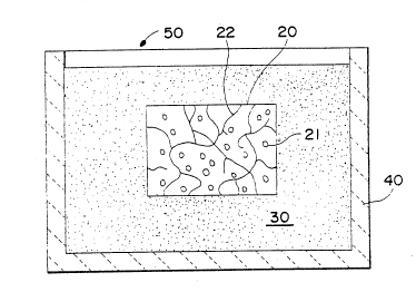
; With reference to Figure la, a composite body 20 contains ceramic
particulate 21 and a metallic constituent 22. The composite body 20 is
substantially completely buried within a filler material 30, which is
contained within an appropriate refractory vessel 40. The fi-ller
material 30 may be any suitable material, as discussed in greater
~. 35 detail below, which is capable of being spontaneously infiltrated by at
I least one metallic component of the metallic constituent 22. An
.~ ,
;~:
~ .
.. - - . ,
.; - :. , : , :
:
~ .- . .,
W O 92/12108 PC~r/US92/00180
2099582
- 18 -
infiltrating atmosphere 50 may be provided such that it can permeate
the filler material 30 and contact at least a portion of the composite
body 20. The refractory container 40, and its contents, may be placed
into a controlled atmosphere furnace to initiate spontaneous
infiltration of at least one metallic component of the metallic
constituent 22 into at least a portion of the filler material 30. In
this embodiment, spontaneous infiltration of said at least one metallic
component of the metallic constituent 22 may be expected to occur from
substantially all surfaces of the composite body 20. Spontaneous
lC infiltration can occur until substantially all of the metallic
component of the metallic constituent has spontaneously infiltrated the
filler material, assuming that the metallic component is substantially
interconnected throughout the composite body, or the spontaneous
infiltration can be terminated by altering at least one of the process
conditions needed to achieve spontaneous infiltration.
Figure lb shows a lay-up similar to that shown in Figure la,
however, rather than surrounding completely the composite body 20 with
f-ller material 30, the composite body 20 is placed into limited
contact with the filler material 30. In this embodiment, selective
removal of at least one metallic component of the metallic constituent
22 from the composite body 20 could be expected to occur at the surface
60, which is an interface between the composite body 20 and the filler
material 30. A similar embodiment to that embodiment shown in Figure
2b would be to surround the composite body 20 with filler material 30
: 25 in an amount which was intermediate between the amounts which are shown
in Figure la and Figure lb.
Another embodiment of the invention is shown in Figure 2. In
this embodiment, a filler material 30 is placed into at least a portion
of a cavity 23 contained within a composite body 20. In this
embodiment, at least one metallic component of a metallic constituent
22 of the composite body 20 can be expected to spontaneously inf;ltrate
the filler material 3Q~ thereby proyiding for a selected or directed
removal of said at least one metallic component of the metallic
constituent 22 from the composite body 20 into substantially only the
filler material 30 located within the cavity 23. If necessary, the
composite body 20 could be contained within any appropriate refractory
.
WO 92/1Z108 2 0 9 9 5 ~ 2 PCI'/US92/00180
- 19 -
vessel during the processing thereof.
It is noted that in each of the Figures, crude representation of
the metallic constituent 22 and ceramic particulate 21 have been made.
It is to be understood that the meta11ic constituent 22 or at least one
metallic component of the metallic constituent 22 could be connected in
only a limited amount or could be highly interconnected. Moreover, the
number and volume percent of phases present in the composite body, the
chemical constituency of the phases, the size and shape of the
phase(s), could vary widely. The Figures are provided only to give a
general understanding of the invention and should not be construed in
any manner as limiting the scope of the invention.
~ Without wishing to be bound by any particular theory or
explanation, when an infiltration enhancer precursor is utilized in
combination with at least one of the metallic constituent or at least
one metallic component of the metallic constituent, and/or filler
, material or preform and/or infiltrating atmosphere, the infiltration
enhancer precursor may react to form an infiltration enhancer which
induces or assists at least one molten metallic component of the
metallic constituent to spontaneously infiltrate a filler material or
preform. Moreover, it appears as though it may be necessary for the
precursor to the infiltration enhancer to be capable of being
positioned, located or transportable to a location which permits the
infiltration enhancer precursor to interact with at least one of the
infiltrating atmosphere, and/or the preform or filler material, and/or
molten metallic component or metallic constituent. For example, in
some metallic component or metallic constituent/infiltration enhancer
~:~ precursor/infiltrating atmosphere systems, it is desirable for the
n infiltration enhancer precursor to volatilize at, near, or in some
.
cases, even somewhat above the temperature at which at least one
metallic component of the metallic constituent becomes molten. Such
volatilization may lead to: (1) a reaction of the infiltration
i enhancer pre~.lJrsor w,th the infiltrating atmosphçre to form a gaseouc
,,
`, species which enhances wetting of the filler material or preform by the
metallic component or metallic constituent; and/or (2) a reaction of
'!' 35 the infiltration enhancer precursor with the infiltrating atmosphere to
1; form a solid, liquid or gaseous infiltration enhancer in at least a
~,
, .~
.;
,~ ' .
. .
:
:~ -
:. ~
WO g2/12108 ~ PCI'/US92/00180
2099~82 `
- 20 -
portion of the filler material or preform which enhances wetting;
and/or (3) a reaction of the infiltration enhancer precursor within the
filler material or preform which forms a solid, liquid or gaseous
infiltration enhancer in at least a portion of the filler material or
preform which enhances wetting; and/or (4) a reaction of the
infiltration enhancer precursor with the molten metallic constituent or
the molten metallic component to form a solid, liquid or gaseous
infiltration enhancer in at least a portion of the filler material or
preform which enhances wetting.
Thus, for example, if an infiltration enhancer precursor was
included or combined with, at teast at some point during the process,
molten metallic component or metallic constituent, it is possible that
the infiltration enhancer precursor could volatilize from the molten
metallic component-or molten metallic çonstituent and react with at
least one component in the filler material or preform and/or the
infiltrating atmosphere. Such reaction could result in the formation
of a solid species, if such solid species was stable at the
infiltration temperature. said solid species being capable of being
deposited on at least a portion of the filler material or preform as,
for example, a coating. Moreover, it is conceivable that such solid
species could be present as a discernable solid within at least a
portion of the preform or filler material. If such a solid species was
formed, the molten metal may have a tendency to react (e.g., the molten
metallic component or metallic constituent may chemically reduce the
formed solid species) such that infiltration enhancer precursor may
become associated with (e.g., dissolved in or alloyed with) the molten
metal. Accordingly, additional infiltration enhancer precursor may
then be available to volatilize and react with another species (e.g.,
the filler material or preform and/or infiltrating atmosphere) and
again form a similar solid species. It is conceivable that a
continuous process of conversion of infiltration enhancer precursor to
infiltraticn enhancer followed by a reduction reaction of the
infiltration enhancer with molten metal to again form additional
infiltration enhancer, and so on, could occur, until the result
achieved is a desirable removal of metallic component or metallic
constituent from the composite body.
, -
, .
..
'
,
WO 92/12108 PCI /US92/00180
2099:~82
- 21 -
In order to effect spontaneous infiltration of the metallic
component or metallic constituent into the filler material or preform,
an infiltration enhancer should be provided to the spontaneous system.
An infiltr~ation enhancer could be formed from an infiltration enhancer
precursor which could be provided (1) in the metallic constituent or in
at least one metallic component of the metallic constituent; and/or (2)
in the filler material or preform; and/or (3) from the infiltrating
atmosphere; and/or (4) from an external source into the spontaneous
system. Moreover, rather than supplying an infiltration enhancer
precursor, an infiltration enhancer may be supplied directly to at
least one of the filler material or preform, and/or metallic
constituent or at least one metallic component of metallic constituent,
and/or infiltrating atmosphere. Ultimately, at least during the
spontaneous infiltration, the infiltration enhancer should be located
in at least a portion of the filler material or preform.
In a preferred embodiment of the invention, it is possible that
the infiltration enhancer precursor can be at least partially reacted
with the infiltrating atmosphere such that the infiltration enhancer
can be formed in at least a portion of the filler material or preform
, 20 prior to or substantially contiguous with contacting the filler
material or preform with at least a portion of the metallic constituent
or at least one metallic component of the metallic constituent (e.g.,
if magnesium was the infiltration enhancer precursor and nitrogen was
the infiltrating atmosphere, the infiltration enhancer could be a
magnesium nitride which would be located in at least a portion of the
preform or filler material).
An example of a metallic component or metallic
constituent/infiltration enhancer precursor/infiltrating atmosphere
;~ system is the aluminum/magnesium/nitrogen system. Specifically, if an
1 30 aluminum metal comprised the metallic component or metallic constituent
', ~ and the aluminum metal was rendered molten, a filler material or
preform could thereafter be contacted with mGlten aluminum metal and he
, spontaneously infiltrated.
Moreover, rather than supplying an infiltration enhancer
precursor, an infiltration enhancer may be supplied directly to at
least one of the preform or filler material, and/or metallic component
.
I
~' - . .
., .
. .
. :. .
WO 92/12108 . : ! PCl/US92/00180
- 22 -
or metallic constituent, and/or infiltrating atmosphere. Ultimately,
at least during the spontaneous infiltration, the infiltration enhancer
should be located in at least a portion of the filler material or
preform.
Under the conditions emp10yed in the method of the present
invention, in the case of an aluminum metallic
component/magnesium/nitrogen spontaneous infiltration system, the
preform or filler material should be sufficiently permeable to permit
the nitrogen-containing gas to penetrate or permeate the filler
~aterial or preform at some point during the process and/or contact the
molten aluminum metallic component. Moreover, the permeable filler
material or preform can accommodate infiltration of the molten aluminum
metallic component, thereby causing the nitrogen-permeated preform to
be infiltrated spontaneously with molten aluminum metallic component
lS from the composite body and/or cause the nitrogen to react with an
infiltration enhancer precursor to form infiltration enhancer in the
filler material or preform and thereby result in spontaneous
infiltration. The extent of spontaneous infiltration and depletion of
aluminum metallic component from the composite body will vary with a
given set of process conditions, including magnesium content of the
aluminum, magnesium content of the preform or filler material, amount
of magnesium nitride in the preform or filler material, the presence of
~, additional alloying elements (e.g., silicon, iron, copper, manganese,
chromium, zinc, and the like), average size of the filler material
; 25 (e.g., particle diameter) or average size of the filler material
comprising the preform, surface condition (e.g., impurities) and type
of filler material or preform, nitrogen concentration of the
infiltrating atmosphere, time permitted for infiltration and
temperature at which infiltration occurs.
Thus, a metallic constituent of a composite body can be at least
partially, or substantially completely, removed by causing at least one
metallic component of .he metallic constituent to spontaneously
infiltrate a permeable mass of filler material or a preform. To
achieve such spontaneous infiltration, at least a portion of the
permeable mass is placed into contact with at least a portion of the
metallic constituent contained within the composite body. Thus, at
.~ ' .
: . . ,; , , . ~
,, , :
~ - ' ' .
wo g2/l2108 2 0 9 9 5 ~ 2 Pcr/usg2/oo180
- 23 -
least a portion of the metallic constituent should be at least
partially accessible, or can be made to be at least partially
accessible, from at least one surface of the composite body.
Specifically, an infiltration enhancer and/or an infiltration
enhancer precursor and/or an infiltrating atmosphere are in
communication with the filler material or preform, at least at some
point during the process, which permits the at least one metallic
component of the metallic constituent of a composite body, when made
molten, to spontaneously infiltrate at least a portion of the filler
material or preform. In a first preferred embodiment, a precursor to
an infiltration enhancer may be supplied to at least one of a portion
of at least one surface of the composite body, and/or diffused into at
least a portion of at least one metallic component or at least a
portion of the metallic constituent of the composite body, and/or mixed
into at least a portion of the filler material or preform which is
placed into contact with at least a portion of the composite body,
and/or contained in an infiltrating atmosphere. The supplied
infiltration enhancer precursor may thereafter react with at least one
of the filler material or preform, and/or at least one metallic
1 20 component in the metallic constituent of the composite body, and/or the
! infiltrating atmosphere, thereby producing infiltration enhancer in at
least a portion of, or on at least a portion of, the filler material or
preform, which in turn is in contact with at least a portion of at
~ least one surface of the composite body. Ultimately, at least during
l 25 the spontaneous infiltration, infiltration enhancer should be in
`~ contact with at least t portion of the filler material or preform.
; In another preferred embodiment of the invention, rather than
- supplying an infiltration enhancer precursor, an infiltration enhancer
may be supplied directly to at least one of the filler material or
preform, and/or metallic constituent of the composite body or at least
; one metallic component of the metallic constituent of the composite
~Q~y; an~!or infiltrating atmosphere. Ultim.`ately, at least during the
spontaneous infiltration, the infiltration enhancer should be in
contact with at least a portion of the filler material or preform
which, in turn, is in contact with at least a portion of the surface of
; the composite body.
.
~.
.~ , .
,
WO 92/12108 PCI'/US92/00180
2099~82
- 24 -
In any of the above-discussed preferred embodiments, the presence
of infiltration enhancer and/or infiltration enhancer precursor in at
least a portion of the filler material or preform may cause at least
one metallic component of the metallic constituent, or substantially
all of the metallic constituent, of the composite body to spontaneously
infiltrate at least a portion of the filler material or preform. The
amount of or selected portion of metallic constituent which is caused
to spontaneously infiltrate the filler material or preform can be
controlled to achieve desirable metal removal. Specifically,
substantially all metallic constituent located in a certain area within
a composite body te.g., located near a surface of the composite body)
may be completely removed from that selected area thereby leaving other
areas of metallic constituent within the composite body substantially
undisturbed. Moreover, if the metallic constituent is substantially
interconnected throughout the composite body, substantially all of the
metallic constituent could be removed. The volumetric amount of
metallic constituent to be removed from the composite body depends upon
the ultimate application for the composite body. Thus, the present
invention may be utilized merely as a surface modification process for
composite products, or it could be used to remove substantially all of
a metallic constituent from a composite product.
Still further, selected portions of the metallic constituent
could be separately removed, leaving behind substantially undisturbed
residual metallic constituent. Specifically, one or more metallic
components of a multi-phase metallic constituent could be removed from
selected~areas of a composite body or could be removed substantially
uniformly from the composite body, depending upon the ultimate
application for the composite body. Such selected removal of one or
more metallic components of a multi-phase metallic constituent could
occur, for example, due to operating at a temperature range within
which only said one or more metallic components were molten and thus
were the only components that were inyolypd in ~he sp~ntaneous
infiltration into the adjacent permeable mass. However, for example,
if the temperature was increased to a range within which all components
of the multi-phase metallic constituent were rendered molten, then the
entire multi-phase metallic constituent may be removable from the
.
WO 92/12108 2 0 9 9 ~ 8 2 PCI'/US92/00180
- 25 -
composite body. Selective removal of at least one component from the
multi-phase metallic constituent could provide for a grading, either
slight or substantial, of the microstructure of a composite body, thus
resulting in graded properties of the composite body~
In another preferred embodiment for removing at least one
metallic component of a metallic constituent from at least a portion of
a composite body, the composite body may be substantially completely
surrounded by a filler material or preform. In this embodiment,
spontaneous infiltration of the filler material or preform by at least
I0 a portion, or substantially all, of the metallic constituent could be
achieved from substantially al-l surfaces of the composite body, so long
as the metallic constitùent is accessible, or could be made to be
accessible, from such surfaces.
In another preferred embodiment for removing at least one
metallic component of a metallic constituent from a composite body,
only a portion of the composite body may be contacted with a permeable
mass of filler material or preform. In this preferred embodiment, at
least one metallic component of the metallic constituent could be
selectively removed from that surface which is in contact with the
permeable mass. In this preferred embodiment, a grading of the
properties of the composite body may be achieved by varying the volume
percent of metallic constituent present from, for example, one side of
the composite body to an opposite side of the composite body. Thus,
this grading of volume percent of metallic constituent within a
composite body could permit the composite body to be utilized for a
number of different conventional applications. Still further, by
contacting only a portion of a composite body with a filler material or
preform, any surface irregularities which may result from the removal
of metallic constituent from a composite body can be substantial7y
confined to that portion of the composite body which contacts the
filler m?terial or preform.
In another prefe.red embodiment, the amount nf infiltration
enhancer and/or infiltration enhancer precursor which is supplied to,
',~ for example, the filler material or preform, can be varied from one
point in the filler material or preform to another point.
Specifically, the amount of spontaneous infiltration of at least one
s
:,
:.. , -
.
WO 92/12108 2 0 9 9 5 8i2 . i, ~, PCl/US92/00180
- 26 -
metallic component of the metallic constituent in the composite body
into an adjacent filler material or preform may be controlled by
controlling the amount of infiltration enhancer and/or infiltration
enhancer precursor provided in the filler material or preform. Thus,
for example, by supplying a greater amount of infiltration enhancer
precursor and/or infiltration enhancer to one side of a composite body
relative to a different side of a composite body, the rate and/or
amount of spontaneous infiltration of at least one metallic component
of the metallic constituent in the composite body can be selectively
controlled. Likewise, by controlling the amount of infiltrating
atmGsphere supplied to, for example, different portions of the filler
material or preform which are in contact with the metallic constituent
of the composite body, the amount of spontaneous infiltration and~or
rate of spontaneous infiltration can also be selectively controlled.
Still further, by controlling the temperature of different portions of
the filler material or preform and/or composite body, the amount of
spontaneous infiltration can also be selectively controlled.
For example, if the metallic constituent of a composite body
comprises aluminum and, if the aluminum contained, or was caused to
contain, by any suitable means, at least about 0.1 percent by weight,
and preferably at least about 1-3 percent by weight, magnesium, based
on alloy weight, the magnesium could function as the infiltration
enhancer precursor and permit spontaneous infiltration to occur in the
presence of, for example, a nitrogenous atmosphere. Additionally,
auxiliary elements contained within, or exposed to the metallic
constituent, may affect the minimum amount of magnesium required in the
aluminum metal to result in spontaneous infiltration of the filler
material or preform. Loss of magnesium from the spontaneous system due
to, for example, volatilization should not occur to such an extent that
no magnesium was present to form infiitration enhancer. Thus, it is
desirable to utilize a sufficient amount of initial elements (e.g.,
magnesium! to assure that spontaneous infiltration will nnt. be
adversely affected by volatilization. Still further, the presence of
magnesium in the preform (or filler material) and/or on at least a
portion of a surface of the composite body, may result in a reduction
or substantially complete elimination of the need for magnesium to be
- ' ' ' ^. '. ' " " . ` ' '
~ , '' .
w o 92/12108 2 0 3 3 J ~ /US92/00180
- 27 -
present in the metallic constituent to achieve spontaneous infiltration
(discussed in greater detail later herein).
The volume percent of nitrogen in the infiltrating atmosphere
also affects spontaneous infiltration rates. Specifically, if less
than about 10 volume percent of nitrogen is present in the atmosphere,
very slow or little spontaneous infiltration will occur. It has been
discovered that it is preferable for at least about 50 volume percent
of nitrogen to be present in the atmosphere, thereby resulting in, for
example, shorter infiltration times due to a much more rapid rate of
I0 infiltration. The infiltrating atmosphere (e.g., a nitrogen-containing
gas) can be supplied directly to the filler material or preform and/or
aluminum metallic constituent, or it may be produced or result from a
decomposition of a material.
The minimum magnesium content required in the aluminum/magnesium/
nitrogen spontaneous system for the molten aluminum to infiltrate a
filler material or preform depends on one or more variables such as the
processing temperature, time, the presence of auxiliary alloying
elements such as silicon or zinc, the nature of the filler material,
the location of the magnesium in one or more components of the
spontaneous system, the nitrogen content of the atmosphere, and the
rate at which the nitrogen atmosphere flows. Lower temperatures or
shorter heating times can be used to obtain spontaneous infiltration as
the magnesium content of the aluminum metallic constituent and/or
contained in the preform is increased. Also, for a given magnesium
content, the addition of certain auxiliary alloying elements into a
metallic constituent, such as zinc, permits the use of lower
temperatures. For example, a magnesium content of the aluminum
metallic constituent at the lower preferred end of the operable range,
e.g., from about 1 to 3 weight percent, may be used in conjunction with
at least one of the following: an above-minimum processing
temperature, a high nitrogen concentration, or one or more auxiliary
alloying elements. When no magnesium is added to the preform~ aluminum
metallic constituent containing, or exposed to, from about 3 to 5
weight percent magnesium are preferred on the basis of their general
utility over a wide variety of process conditions, with at least about
5 percent being preferred when lower temperatures ahd shorter times are
.
WO 92/12108 PCt/US92/00180
2~99~82
- 28 -
employed. Magnesium contents in excess of about 10 percent by weight
of the aluminum metallic constituent may be employed to moderate the
temperature conditions required for infiltration. The magnesium
content may be reduced when used in conjunction with an auxiliary
alloying element, but these elements serve an auxiliary function only
and are used together with at least the above-specified minimum amount
of magnesium. Thus, it is possible to determine the amount of, for
example, magnesium which may be required to achieve spontaneous
infiltration behavior in the aluminum/magnesium/nitrogen spontaneous
system. Accordingly, a metallic constituent in a metal reinforced
ceramic body or in a ceramic reinforced metal body can be manufactured
- so as to contain the required amount of magnesium.
It is also noted that it is possible to supply to the spontaneous
system, infiltration enhancer precursor and/or infiltration enhancer on
a surface of the composite body and/or on a surface of the preform or
filler material and/or within the preform or filler material prior to
infiltrating the metallic constituent or at least one metallic
component of the metallic constituent into the filler material or
preform (i.e., it may not be necessary for the supplied infiltration
enhancer or infiltration enhancer precursor to be alloyed with the
metallic constituent, but rather, simply be supplied to the spontaneous
system). For example, in the aluminum/magnesium/nitrogen system, if
the magnesium was applied to a surface of the composite body it may be
preferred that the surface should be the surface which is closest to,
or preferably in contact with, the permeable mass of filler material or
vice versa; or such magnesium could be mixed into at least a portion of
the preform or filler material. Still further, it is possible that
some combination of surface application, alloying and/or placement of
magnesium into at least a portion of the filler material or preform of
i 30 filler material could be used. Such combination of applying
infiltration enhancer(s) and/or infiltration enhancer precursor(s)
could result in a decrease in the total weight percent of magnesium
needed to promote infiltration of the aluminum metallic component into
the filler material or preform of filler material, as well as achieving
lower temperatures at which infiltration can occur.
The use of one or more auxiliary alloying elements and the
: -
.. . . .
- ~ , , .
. . ' ' . ' :
~, -
.~ . .
WO 92/12108 PCr/US92/00180
2099a82
- 29 -
concentration of nitrogen in the surrounding gas also affects the
extent of nitriding of the metallic constituent or at least one
metallic component of metallic constituent at a given temperature. For
example, auxiliary alloying elements such as zinc or iron included in
the metallic constituent and/or placed on a surface of the composite
body, and/or mixed within the filler material or preform, may be used
to reduce the infiltration temperature and/or increase the amount or
rate of infiltration at a particular temperature.
The concentration of magnesium in the metallic constituent,
and/or placed onto a surface of the composite body, and/or combined in
the filler or preform material, also tends to affect the extent and/or
rate of infiltration at a given temperature. Consequently, in some
cases where little or no magnesium is contacted directly with the
preform or fiiler material, it may be preferred that at least about
three weight percent magnesium be included in the metallic constituent.
Alloy contents of less than this amount, such as one weight percent
magnesium, may require higher process temperatures or an auxiliary
alloying element for infiltration. The temperature required to effect
the spontaneous infiltration process of this invention may be lower:
(1) when the magnesium content of the metallic constituent alone is
increased, e.g., to at least about 5 weight percent; and/or (2) when
alloying constituents are mixed with the permeable mass of filler
material or preform; and/or (3) when another element such as zinc or
iron is present somewhere in the system. The temperature also may vary
with different filler materials. In general, in the aluminum metallic
component/magnesium/nitrogen spontaneous system, spontaneous and
` progressive infiltration will occur at a process temperature of at
least about 675-C, and preferably at a process temperature of at least
about 750-C-850-C. Temperatures generally in excess of 1200-C do not
appear to benefit the process, and a particularly useful temperature
range has been found to be from about 675-C to about 1000-C. However,
as 2 general rule, the spontaneous infiltration tempPrature iS a
temperature which is above the melting point of at least one metallic
component of the metallic constituent but below the volatilization
temperature of said metallic component. Moreover, the spontaneous
infiltration temperature should be below the melting point of the
', ' ' ~ "-
.: . .
WO 92/12108 . . PCI`/US92/00180 ~
~,.. ..
2099582 30 -
filler material. Still further, as temperature is increased, the
tendency to form a reaction product between at least one metal1ic
component of the metallic constituent and the infiltrating atmosphere
increases (e.g., in the case of aluminum metallic component and a
nitrogen infiltrating atmosphere, aluminum nitride may be formed).
Such reaction product may be desirable or undesirable. Additionally,
electric resistance heating is typically used to achieve the
infiltrating temperatures. However, any heating means which can cause
said at least one metallic component to become molten and does not
adversely affect spontaneous infiltration, is acceptable for use with
the invention.
In the present method, for example, a permeable filler material
or preform comes into contact with molten aluminum component of the
composite body in the presence of, at least sometime during the
process, a nitrogen-containing gas. The nitrogen-containing gas may be
supplied by maintaining a continuous flow of gas into contact with at
least one of the filler material or preform and/or molten aluminum or
by containing the preform or filler material in a closed or static
atmospheric system. Although the flow rate of the nitrogen-containing
gas is not critical ~e.g., flowing nitrogen may not even be essential),
it is preferred that a flow rate be established such that, for example,
the flow rate is sufficient to compensate for any nitrogen lost from
the atmosphere due to any nitride formation, and also to prevent or
inhibit the incursion of air which can have an oxidizing effect on one
or more metallic components of the metallic constituent.
~ he method of removing at least one metallic component of a
metallic constituent from a composite body is applicable to a wide
variety of filler materials, and the choice of filler materials will
depend on such factors as the composition of the metallic constituent,
the process conditions, and the reactivity of the metallic constituent
with the filler material. For example, when the metallic constituent
comprises aluminum., suit2ble filler materials inclllde (2) o~ides, e.g.
alumina, magnesia, zirconia; (b) carbides, e.g. silicon carbide; (c)
borides, e.g. aluminum dodecaboride, titanium diboride, and (d)
nitrides, e.g. aluminum nitride, silicon nitride, and (e) mixtures
thereof. Further, the filler material or preform may be homogeneous or
,,
, .
:
. ~ , . .. ; ., . ~ , .
- ., " .
... . ..
.
,- :. ~ . . : . ...
WO 92/12108 2 0 9 9 ~ 8 2 PCr/US92/00180
- 31 -
heterogeneous. If the filter material or preform were heterogeneous,
it is possible that selective removal of metallic constituent could
occur. For example, under a given set of reaction condit;ons, one
filler material could be infiltrated at a faster rate relative to
another filler material. Thus, by proper choice of combination of
filler materials (e.g., by using particle size and/or chemical
composition) metal could be withdrawn in differing amounts from
different portions of a composite body, thereby resulting in graded
properties in the composite body.
It may also be desirable to utilize a barrier means in
combination with the present invention. Specifically, as shown in
Figure 3, a barrier means 70 may at least partially, or substantially
completely, surround a composite body 20, which itself is surrounded by
a filler material 30, and contained within the barrier material 70.
The barrier material 70 may than serve as a limiting means for removing
metallic constituent from the composite body 20. Specifically, once
spontaneous infiltration of at least one metallic component of the
metallic constituent 22 of the composite body 20 had begun and had
reached the barrier means 70, the barrier means 70 could prevent any
further spontaneous infiltration of said metallic component from the
composite body 20. Thus, the use of a barrier means may provide a
control of the amount of said metallic component to be removed from the
composite body 20.
As shown in Figure 3, the barrier means miy be supported by a
suitable substantially inert material 80. The barrier means for use
with this invention may be any suitable means which interferes,
inhibits, prevents or terminates the migration, movement, or the like,
of molten metallic constituent beyond the surface boundary of the
barrier. Suitable barrier materials may be any material, compound,
element, composition, or the like, which, under the process conditions
of the invention, maintains some integrity, is not volatile and
preferably, at least in some cases, is permeable to the infiltration
atmosphere which may be used with the process, as well as being capable
of locally inhibiting, stopping, interfering with, preventing, or the
like, continued infiltration or any other kind of movement beyond the
surface boundary of the barrier.
'.
.' '
: ,
. .
WO 92~12108 PCI'/US92/00180
2099~82
- 32 -
Suitable barr;er means includes materials which are substantially
non-wettable by the migrating molten metal under the process conditions
employed. A barrier of this type appears to exhibit little or no
affinity for the molten metal, and movement beyond the defined surface
boundary of the filler material or preform is prevented or inhibited by
the barrier means. As stated above, the barrier preferably should be
permeable or porous, or rendered permeable by puncturing, to permit the
infiltrating atmosphere to contact the molten matrix alloy.
Suitable barriers particularly useful for aluminum metallic
components are those containing carbon, especially the crystalline
allotropic form of carbon known as graphite. Graphite is essentially
non-wettable by the molten aluminum alloy under the described process
conditions. Particular preferred graphites are graphite foil products
that are sold under the trademark GRAFOIL~ graphite foil, registered to
Union Carbide and under the trademark PERMA-FOIL graphite foil,
distributed by TTAmerica. These graphite foils exhibit sealing
characteristics that prevent the migration of molten aluminum alloy
beyond the defined surface boundary of the filler material. These
graphite foils are also resistant to heat and are chemically inert.
GRAFOIL~ graphite foil and PERMA-FOIL graphite foil are flexible,
compatible, conformable and resilient. They can be made into a variety
of shapes to fit any barrier application. However, graphite barrier
means may be employed as a colloidal suspension, a slurry or paste or
even as a paint film around and on the boundary of the filler material
or preform. GRAFOIL~ graphite foil and PERMA-FOIL graphite foil are
particularly preferred because they are in the form of a flexible
graphite sheet. In use, these paper-like graphites are simply formed
around the filler material or preform.
Other useful barriers for aluminum metal in nitrogen include low-
volatile organic compounds applied as a film or layer onto the externalsurface of the filler material or preform. Upon firing in nitrogen,
e~peci~lly at, the proces~ condit,ions sf this invention, the organic
~` compound decomposes leaving a carbon soot film. The organic compoundmay be applied by conventional means such as by painting, spraying,
dipping, etc.
Moreover, finely ground particulate materials can function as a
:
WO 92/12108 PCl`/US92/00180
2099~82
- 33 -
barrier so long as infiltration of the particulate material would occur
at a rate which is slower than the rate of infiltration of the filler
material.
Thus, the barrier means may be applied by any suitable means,
such as by covering the defined surface boundary with a layer of the
barrier means. Such a layer of barrier means may be applied by
painting, dipping, silk screening, evaporating, or otherwise applying
the barrier means in liquid (e.g., colloidal graphite suspension),
slurry, or paste form, or by sputtering a vaporizable barrier means, or
by simply depositing a layer of a solid particulate barrier means, or
by applyin~ a solid thin sheet or film of barrier means onto the
defined surface boundary. With the barrier means in place, spontaneous
infiltration substantially terminates when the infiltrating metal
reaches the defined surface boundary and contacts the barrier means.
lS Various demonstrations of the present invention are included in
the Examples immediately following. However, these Examples should be
considered as being illustrative and should not be construed as
limiting the scope of the invention as defined in the appended claims.
ExamDle 1
A ceramic matrix composite body made substantially in accordance
with the teachings contained in U.S. Patent No. 4,851,375, was
formulated. Specifically, the ceramic matrix composite body comprised
a S00 grit (average particle diameter of about 17 microns) silicon
carbide reinforcement which had been embedded by an oxidation reaction
product matrix comprising alumina and a metallic component comprising
an aluminum alloy which was at least partially three dimensionally
interconnected in the composite body.
After formation of the silicon carbide particulate reinforced
alumina composite body had been achieved, the metal removal process was
`, effected. Specifically, a material mixture was formed, comprising byweight about 90 percent f~ller, which cnns;~ted nf ~on arit (aYerage
particle diameter of about S microns) A1203 (E67 tabular alumina,
Norton Co., Worcester, MA) and about 10 percent -325 mesh (particle
diameter less than about 45 microns) magnesium powder (AESAR~, Johnson
Matthey, Seabrook, NH). The material mixture was mixed in a plastic jar
~,' .
. . .
. -
,
., ~.
WO 92/12108 pcr/us92/oo18o
20995~2` ` ` '
- 34 -
on a rotating jar mill for about an hour.
Two graphite foil boxes having inner cavities measuring about 3
inches (76 mm) long, about 3 inches (76 mm) wide and about 2.5 inches
(64 mm) deep were made from graphite foil (PERMA-FOIL, TTAmerica,
Portland, OR). The graphite foil boxes were made from pieces of
graphite foil, measuring about 8 inches (203 mm) long by about 8 inches
(203 mm) wide and about 0.15 inches t4 mm) thick. Four parallel cuts
about 2.5 inches (64 mm) from the side and about 2.5 inches (64 mm)
long, were made into the graphite foil. The graphite foil was then
folded into the graphite foil box and stapled together. Sample A,
referred to in Table 1, was prepared for i;reatment by first pouring
about 0.5 inch (13 mm) of the mixture of filler material and magnesium
powder into one of the graphite foil boxes. The filler material
mixture was levelled and hand tapped until smooth. A bar of the
silicon carbide particulate reinforced alumina composite discussed
above, and measuring about 1.7 inches (43.8 mm) long by about 0.25 inch
(6.3 mm) wide and about 0.2 inch (4.5 mm) thick was placed onto the
filler material mixture within the graphite foil box and covered with
about another 0.5 inch (13 mm) of the filler material mixture which was
again levelled and hand tapped until smooth.
Sample B, not specifically referred to in any Table, was prepared
for treatment by first pouring about one inch (25 mm) of the same
filler~ material mixture used for Sample A into the second graphite foil
box. The filler material mixture was levelled and again hand tapped
until smooth. Another silicon carbide particulate reinforced
composite, discussed above, measuring about 1.7 inches (43 mm) long by
about 0.25 inch (6.3 mm) wide and about 0.2 inch (4.5 mm) thick was
placed onto the filler material mixture and forced into the filler
material mixture such that five sides of the composite body contacted
the filler material mixture (i.e., was buried within the filler
material mixture) and one side of the composite body measuring about
Q.55 inch (6.3 mm~ by 2bout 1.7 inches (43 mm~ W25 substanti211y flush
with the surface of the filler material mixture and thus would be
exposed to the infiltrating atmosphere, when supplied.
Both graphite foil boxes containing Samples A and B,
respectively, were then placed into a solid graphite refractory
. . .
.
.- . . . ...
.~ :
.
Wo 92/t2108 PCI /US92/00180
35 9~2
container having inner dimensions of about 9 inches (229 mm) long,
about 9 inches (229 mm) wide, about 5 inches (127 mmj deep and having a
wall thickness of about 0.5 inch (13 mm). The graphite refractory
container and its contents were then placed into a controlled
atmosphere resistance heated furnace, the furnace door was closed and
the furnace was evacuated to at least about 30 inches (762 mm) of
-mercury vacuum. After about 15 hours at about 30 inches of mercury
vacuum, the vacuum was shut off and nitrogen gas was introduced into
the furnace chamber at a flow rate of about 2 liters/minute. The
operating pressure of the chamber was about 16.7 pounds per square inch
(1.2 kg/cm2) with a nitrogen flow rate of about 2 liters/minute. The
furnace was heated to about 850-C in about 4 hours. After about 10
hours at about 850'C, the power to the furnace was interrupted and the
graphite refractory container and its contents were allowed to cool
within the furnace to about room temperature. Once at room
temperature, the graphite refractory container and its contents were
removed and the lay-ups for each of Sample A and Sample B were
disassembled to reveal that the metallic constituent comprising an
aluminum alloy in each of the silicon carbide particulate reinforced
alumina composite had been drawn out from each composite body during
the process.
Thus, this Example demonstrates that the metallic constituent of
a composite body can be drawn out by processing the body in a filler
material mixture comprising a substantially inert component and an
infiltration enhancer precursor. Moreover, this Example demonstrates
that the metallic constituent of a composite body can be removed either
by surrounding a composite body with a filler material mixture or by
selectively contacting the filler material mixture with a surface of
the composite body and thus, directionally removing at least a portion
of the metallic constituent from the composite body. Specifically,
Figure 4a is a photomicrograph taken at about 200x of the
mic~ostructure of the silicon carbide particulate reinforced alu~ina
composite prior to metal removal and Figure 4b is a photomicrograph
taken at about 200x of the microstructure of the silicon carbide
particulate alumina composite after metal removal.
W O 92/12108 PCT!US92/00180
2 0 9 9 ~ ~ 2 36 -
ExamDle 2
This Example illustrates that a variety of filler material
mixtures comprising a substantially inert filler material or a reactive
filler material can be used in combination with an infiltration
enhancer precursor to remove at least a portion of a metallic
constituent from metal reinforced ceramic composites (i.e., ceramic
matrix composites). Specifically, the substantially inert filler
materials used in this Example include A12~3, BN, and SiC coated BN,
while the substantially reactive filler material used in this Example
includes PYREX~ glass powder (Corning ~lass Works, Corning, NY).
Table I contains the experimental parameters for Samples A, C, D,
and E. Specifically the Table contains a description of the ceramic
matrix composite body (which was substantially the same as the ceramic
composite body discussed in Example 1) from which the metallic
constituent was removed, the dimensions of the ceramic matrix composite
body, the weight of the filler material, the weight percent of
infiltration enhancer precursor added to the filler material to form
the filler material mixture, the processing temperature, the processing
time at the processing temperature and the processing atmosphere.
Figure la shows a cross-sectional schematic view of a setup similar to
the ones used for this Example.
The setups comprised a graphite refractory container, which
contained a filler material mixture comprising a substantially inert
'
.
; . -
"
20995~
wo 92/12108 37 PCI~/US92/00180
E N
Z Z Z Z
a~ .
t
C C
._ ~ .~ ~
t~ C~ t~ O ~ ~ O
~I E ~ c
o ~ I
C-~
a~
C
_
t~ o O O o
~ ~ U'~
t~ C ~ Co o~
O E
C S S ~
. C o , ,c ,_ _
a v~ v~ 'Jl
~) t ~ C~ ~ C)
~ ~J o E E E E
-- ~ a) u~
_ C I C~
O o o o
_ ~ C~
_ . . I 0~
c: a~ ~ ~ ._ _
) 3 C::-
c ~ ~ ta CL E
_ a:~ ~ "' = z
_ ~ ~ 3
._ O ~, ~ Z O C
.~
aJ , O 3 ~
~ o ~ o
t -- ' Z
t t~
o
>~ D .0 CL C~ V~ -- c
E E q o ^ '~ 3 '
O X X X X - C_ ~
X X X x E. ~ . C
Ln , 0,_ ~
~a - cL Z c s_
~ Cv O -~_
O O O O ~J s~ c ~
~ vv ~ a o -
a Cc ~ ~ ~ .~ 3 ~ ,_~ s_ ~
r~ ~ a) _~ E ~ s_
I v~vr~ ) 3 3 o
E ~ ~ ~ ~ .,_) r_~ o -- ~ s_
C s_'s_ '~ s_ a ~ o
G.Gi G. G _ G C o vi
O O O O ._ s 7 ~ __
n Ln Ln s_ z 0_ ,~ a
C c -c: o x
a . ~ ~ ~ O
c . ~ C ~ ~ v~
E .
V7 C ~ ' C~ L~l ~ ~ Lr~
,
,
WO 92~12108 . PC'r/US92/OOt80
2099~82
- 38 -
filler material and an infiltration enhancer precursor, in the relative
amounts shown in Table I, and which surrounded the SiC particulate
reinforced alumina body, as shown in Figure la. Each setup
corresponding to Samples C, D, and E (note that Sample A was discussed
in Example 1) were placed into a resistant heated controlled atmosphere
furnace and nitrogen was introduced into the furnace at a flow rate of
about O.S liters/minute. The furnace was then heated to the processing
temperature, as specified in Table I, at a rate of about 200'C/hour,
held at the respective processing temperatures for the respective
processing times shown in Table I, during which time the metal1ic
constituent from within the ceramic matrix composite body spontaneously
infiltrated the filler material mixture. After processing each of the
samples for the respective times shown in Table I, the furnace was
cooled to about room temperature. Once at room temperature, each setup
was removed from the furnace and disassembled. It was noted that for
- Samples A, C, D, and E, substantially all of the metallic constituent
had been removed from each ceramic matrix composite body.
ExamDle 3
This Example illustrates that varying amounts of an infiltration
enhancer precursor can be combined with a filler material, to make a
filler material mixture, so that at least a portion of the metallic
constituent can be removed from ceramic matrix composite bodies. In
this Example -325 mesh (particle diameter less than about 45 ~m)
magnesium powder (AESAR, Johnson Matthey Corp., Seabrook, NH) was used
as the infiltration enhancer precursor.
- Table II contains the experimental parameters for Samples A, F,
G, and H. Specifically, Table II contains the ceramic matrix composite
body from which at least a portion of the metallic constituent was
removed, the dimensions of the ceramic matrix composite body, the
weight percent of filler material, the weight percent of infiltration
enhancer precursor added to the filler material to form the filler
material mixture, the processing temperature, the processing time at
- processing temperature, and the processing atmosphere. The ceramic
matrix composite bodies utilized in this Example and the method for
forming the filler material mixtures were substantially the same as
; , .
WO 92/12108 2 0 9 9 ~ 8 ~ PCl`/US92/00180
- 39 - -
that described for Sample A in Example 1.
The refractory containers for Samples F, G, and H were high
density alumina crucibles having an inner diameter of about 2.3 inches
(59 mm), a depth of about 2.3 inches (5.9 mm) and a wall thickness of
about 0.04 inch (1 mm). Figure la shows a cross-sectional schematic
view of the setup used for Sample F, G, and H to remove the metallic
constituent from the silicon carbide particulate reinforced alumina
composite.
The weight percentage of infiltratiGn enhancer precursor mixed
with the filler material, as shown in Table I~, was about 10 weight
percent for Sample A, about 20 weight percent for Sample F, about 40
weight percent for Sample G, and about 100 weight percent for Sample H.
The setup for each Sample comprised a refractory container
containing the filler material mixture comprising the filler material
and the infiltration enhancer precursor and surrounding the silicon
carbide particulate reinforced alumina composite body. The setup was
placed into a resistance heated controlled atmosphere furnace and
nitrogen was introduced. The processing conditions for Sample A are
described in Example 1. The processing conditions fur Samples F, G,
and H include flowing nitrogen at about 0.5 liters/minute. The furnace
was heated to about 850 C at a rate of about 200-C/hour and held at
about 850-C for about 10 hours, during which time the metallic
constituent from within the ceramic matrix composite body spontaneously
wetted the filler material mixture comprising the alumina filler
material and the infiltration enhancer precursor. After about 10 hours
at about 850-C, the furnace and its contents were cooled to about room
temperature. At about room temperature, the setup was removed from the
furnace and disassembled to reveal that substantially all of the
metallic constituent had been removed and that Samples A, F, G, and H
now comprised silicon carbide particulate reinforced alumina composites
with three dimensionally interconnected porosity and an alumina matrix.
~ Example 4
; This Example illustrates that a range of processing temperatures
may be used to remove the metallic constituent from ceramic matrix
WO 92/1 2 1 08 2 0 9 9 ~ 8 2 Pcr/ US92/00 1 80
~ N
'1:1 Z Z Z Z
a)
C~ C~
._ ~ _ ~ c c - c
~ V~ ' O O o o
a~ 2) a ~ ~
C~ E
C \_ C
G~
,c ~
a ~ O O O
V7 ' O o O O
cl
O ~
C~--
S ~ S S
O ' s ~ C
._ ' O V) Vl ~ ~
c c ~ E E E E
s a~ ~, Ln L~
._ C ~ ~ ~ ~
L J CL I ~ I I
O O O O
~ ~ C o
_
~ _ ~ C~
~ ~ O O O
J C~
cr ~ C c~: C 'S
Z ~ ~ ~ CL
.~ E
c c c a
_ O O O Q~ 3
._ O o o C ~1)
O O O O Z
C
o
~ O
C
o
L C a
E E E E E
O ~ ~ ~ ~ o
a~ x x x x ~ ~ ~--
X X X E C~
_ ~ o
a 3 CL
~ O
~ 0 0~ ' o ~o
C C C~ C ~ C ~
. ~ 2
C ~ .~ C
g g o g ¦ ~ E r~
Ln _ _
o c~ ~&
a~ ~ ~
. . (,~ L-~ C
E c~ _ ~ c~7
w o 92/12108 2 0 9 9 ~ 3 2 PCT/US92/00180
composite bodies according to the instant invention. Specifically, the
processing temperatures in this Example were about 650'C for Sample I,
about 750-C for Sample J, about 850-C for Sample K, about 950-C for
Sample L, and about 1050-C for Sample M.
Table III contains the experimental parameters used for Samples
I, J, K, L, and M. Specifically Table III lists the ceramic matrix
composite bodies from which the metallic constituent was removed, the
dimension of the ceramic matrix composite body, the filler material,
the infiltration enhancer precursor, the processing temperature, the
processing time at the processing temperature, and the processing
atmosphere. The ceramic matrix composite bodies tested in this Example
and the method for making the filler material mixture were
substantially the same as that described for Sample A in Exarple 1.
Figure la shows a cross-sectional schematic view of the setup
used with Samples I through M to remove the metallic constituent from
the silicon carbide particulate reinforced alumina composite in this
Example. Each experimental setup in Table III comprised an alumina
crucible, a filler material mixture comprising a filler material and an
infiltration enhancer precursor, and a silicon carbide particulate
reinforced alumina composite body surrounded by the filler material
mixture and contained within the alumina crucible. The alumina
crucible for the setup used with Sample I was obtained from Netzche,
Inc., Exton, Pennsylvania and had an inner diameter measuring about
0.23 inch (6.0 mm) wide by about 0.51 inch (13 mm) deep. The alumina
crucibles for the setups used with Samples J, K, L, and M were obtained
from McDanel Refractory Co., Beaver Falls, Pennsylvania and measured
about 3.9 inches (100 mm) long by about 1.8 inches (45 mm) wide by
about 0.75 inch (19 mm) tall.
The setups were placed into a resistance heated controlled
; 30 atmosphere furnace and nitrogen was introduced. For Sample I, thenitrogen flow rate was about 0.5 liters/minute. For Samples J, K, L,
and M, the nitroqen flow rate was about 1.0 liter!minute. The furnace
and its contents were then heated at about 200-C per hour to about the
processing temperature specified in Table III. After about the
- specified time in Table III at the specified temperature, during which
time the metallic constituent from within the ceramic matrix composite
WO 92/12108 2 0 9 9 ~ 8 2 4;~ _ PCI`/US92/00180
.
E C~
C~ Z Z Z Z Z
C~
C C
_ ~ _ ~
c ~ a ~c
V~ ~ C U~ c c ,c ~
a~ ~ ~ a~ o o o o
~ E ~ ~ _ _ _ _ _
O--- O E
t
C~
'
C
_ ~ ~ ~ ~ ~ o
V~ ~1 o o o o O
V~ o o o o U~
QJ CV ~ U~ Ln ~ O
c~ ~ ~D r~ CO ~ ~
o E
C~
S S S S S
C c _ c ~ c
o ~ V~
_ ~ O CJ CV ~V F CV
V ~ ~ _
c I ~ Ln u~ In Ln
C~l
C C
~C
C ~ ~ ~ ~ ~
-- O O O O O
_, _l _ _ _
_ ; C~
a OCOOO
LLJ ._ ~J NC~J N C~
cr~ I ~
a: ~ ~ ~ ,~ c
~ .~ .~ ._._ ._ ~L
cV r <_ ~ ~ e
O O O O O
, o o o O 0 3
._ o o o o o ~
L~_ _ _ _ _ _ Z
ClJ o,
c ~ ~ v) D
D D D D o
C c~
_ E E E E E ~ u)
aJ E E E E E u ^ ^
E ~ ~ c~ ~ ' c
O U~ V O
C':~ X X X X X C ~ --
x x x x X E ~) ~
~'7 ~> ~ o Q
3 '
.~
~ ~ c~ tY7 ~ a) ^
o o o o o ~ -
~ O C_~
~ ~Q ~Q ~ --Q --Q ~- o
V~ ~ C_~ V ~
o V~ ~ o
o CV Z C
E ~-- ~ ~ ~ ~ _~ o
; O ~ 't t ~ t ,- ~ C
~" ~.,_., _
: o o o I -- E -~
o o o o o I ~_,
: c~ I Ql_ C
_ ' ~ ~
r ~ C
.~ ~L
~ E
-
WO 92/12108 2 0 9 9 ~ 8 2 PCT/US92/00180
- 43 -
body spontaneously wetted the filler material mixture comprising of the
filler material and the infiltration enhancer precursor, the furnace
and its contents were allowed to cool to about room temperature. At
about room temperature, each setup was removed from the furnace,
disassembled, and it was noted that the samples experienced a weight
loss due to the removal of the metallic constituent from within the
ceramic matrix composite body. The weight loss for Samples G, J, K, L,
amd M indicated that substantially all of the metallic constituent had
been removed from the ceramic matrix composite body.
ExamDle S
This Example illustrates that the instant invention for removing
the metallic constituent from ceramic matrix composite bodies is
applicable to large and complex shaped composite bodies.
A conically shaped preform having substantially paraboloidal
outer and inner surfaces and measuring about 5.0 inches (127 mm) high
and having an outer diameter measuring about 4.0 inches (102 mm) at the
end opposite the nose end of the conically shaped preform was slip cast
from a slip mixture comprising by weight about 56.2% 1000 grit (a~erage
particle diameter of about 5 ~m) fired 39 CRYSTOLON~ silicon carbide
(Norton Company, Worcester, Massachussetts), about 15% submicron
(average particle diameter of about 0.6 ~m) silicon carbide (HSC-059 or
100 GL, Superior Graphite, Chicago, Illinois), about 3.8% fired 39
CRYSTOLON~ 500 grit (average particle diameter of about 17 ~m) silicon
carbide (Norton Company, Worcester, Massachussetts), about 24.5% water,
and about 0.5% DA~VAN~ 821A organic dispersant (R. T. Vanderbilt Co.,
Inc., Norwalk, Connecticut). The fired silicon carbide was heated in
an air atmosphere resistance heated furnace from about 1300C to about
1325-C for about 48 hours. The slip mixture was placed in an about 5
gallon ~19 liter) plastic container which was about half full of
alumina grinding media having a diameter of about 0.5 inch (13 mm) and
the plastic container and its contents were placed on a rotatina iar
mill for about 3 days. The slip mixture was then cast into a plaster
of Paris mold having a paraboloidal inner cavity corresponding
substantially to the outer surface of the desired conical shaped
preform. A rubber mandrel having a paraboloidal outer surface
WO 92/12108 PCI`/US92/00180
2~99~82
corresponding substantially to the inner surface of the desired conical
shaped preform was then inserted into the preform mixture contained
within the plaster of paris mold. After about 5 hours, the rubber
mandrel was removed from within the set slip mixture and the conically
shaped preform was removed from the plaster of paris mold. After the
conically shaped preform had dried for at least 12 hours, it was placed
into an air atmosphere furnace and heated to about 1025-C in about 10
hours, held at about 1025-C for about 24 hours and cooled to about room
temperature in about 10 hours.
The outer surface of the fired conically shaped preform was first
sanded by hand and then coated with a barrier mixture comprising by
weight about SOYO -325 mesh (particle diameter less than about 45 ~m)
wollastonite and about 50% YK paint thinner (ZYP Coating~ ~ak Ridge,
Tennessee). The barrier coated conically shaped preform was placed
into a refractory boat such that the nose of the barrier coated
conically shaped preform was against the bottom of the refractory boat
and the opening of the conically shaped void within the preform was up.
The refractory boat and its contents comprising the barrier
coated conically shaped preform were placed into an air atmosphere
resistance heated furnace and the furnace was heated to about 1000-C in
about 8 hours. A refractory crucible containing a parent metal
comprising by weight about 15.0% Si, 6.0Yo Zn and the balance aluminum
was inserted into the furnace at about lOOO-C and when the parent metal
had substantially completely melted, the parent metal was poured into
the conically shaped void within the preform to fill the void.
Additional molten parent metal was added to the conically shaped void
on a daily basis throughout the about 100 hour growth at about 1000C.
After about 100 hours at about lOOO-C, the conically shaped preform was
observed in the furnace and it was determined that the oxidation
reaction product had grown into and substantially completely embedded
the silicon carbide particulate preform thereby forming a substantially
net shaped s~licon carbide particulate reinfnrced alumina cnnically
shaped composite body. The remaining parent metal within the void of
the conically shaped composite body was poured out and the power to the
furnace was interrupted and the furnace.containing the refractory boat
containing-the conically shaped composite body were allowed to cool to
.
.
WO ~2t12108 PCI`/US92tO0180
20~9~2
- 45 -
about room temperature. At about room temperature, the conically
shaped composite body was subjected to sand blasting to remove any
remnants of the barrier material on the outer surface of the conically
shaped composite body and prepare it for the metallic constituent
removal process of the instant application.
Figure 2 shows a portion of a cross-sectional schematic view of a
set-up which is similar to that setup which was used to remove the
metallic constituent from the conically shaped composite body.
Specifically, Figure 2 shows a representative set-up comprising a
composite body 20 (i.e., in this Example the numeral 20 represents a
silicon carbide particulate reinforced, conically shaped composite
body), that served as a container for the filler material mixture 30.
In this Example, the filler material mixture 30, comprised by weight
about 90% E67 100 grit taverage particle diameter of about 173 ~m)
` 15 alumina (Norton Company, Worcester~ Massachussetts) and about 10% -325
mesh (particle diameter less than about 45 ~m) magnesium powder
(AESAR~, Johnson Matthey Corporation, Seabrook, New Hampshire). The
conically shaped composite body was supported on its outside portions
by 38 ALUNDUM~ 220 grit (average particle diameter of about 66 ~m)
alumina (Norton Company, Worcester, Massachussetts) which was contained
within a steel box, both of which are not shown in Figure 2.
The set-up, comprising the steel box which contained 220 grit
(average particle diameter of about 66 ~m) alumina, which alumina
supported the exterior portion of the conically shaped composite body
20, which composite body 20 also contained the filler material mixture
30, was placed into a retort-lined resistant heated furnace. The
retort door was closed and nitrogen was introduced into the retort at a
flow rate of about five liters per minute. The furnace and its
contents were heated to about 800-C at a rate about 200C per hour with
a flow of nitrogen of about five liters per minute. After about 10
hours at about 800-C with a flow of nitrogen at about five liters per
minute the power to the furnace was interrupted and the furnace and
its contents were allowed to cool to about room temperature. At about
room temperature, the retort door was opened, the set-up was removed
from the furnace and disassembled to reveal that the filler material
mixture adjacent to the interior surface of the conically shaped
WO 92/12108 PCl/US92/00180
209~82 - 46 -
composite body now comprised an agglomerated mass comprising 1000 grit
alumina, aluminum nitride, and aluminum alloy. Also, it was observed
from a polished cross-section of the conically shaped composite body
that the metallic constituent had been removed. Specifically, Figure
5a shows a conically shaped composite body prior to treatment by the
instant invention and Figure 5b shows a conically shaped composite body
after treatment by the instant invention to remove the metallic
constituent. Figure 6a is a photomicrograph taken at about lOOOX,
which corresponds to the microstructure of the silicon carbide
reinforced alumina composite prior to treatment by the instant
invention. Specifically, the microstructure shows that the composite
body comprises silicon carbide particulate reinforcement (shown as
discrete gray regions in the micrograph), interconnected metallic
channels (shown as the speckled or mottled white region in the
micrograph) and an alumina matrix growth product (shown as grayish-
black regions in the micrograph). In contrast, Figure 6b is a
photomicrograph taken at about lOOOX, which corresponds to the
microstructure of a silicon carbide reinforced alumina conically shaped
composite body treated by the instant invention. Specifically, the
microstructure shown in Figure 6b shows that the composite body, after
metal removal treatment, comprises silicon carbide particulate
reinforcement (shown as discrete gray regions in the micrograph),
porosity (shown as discrete black regions in the micrograph) in place
of the metallic channels, some isolated residual metal ~shown as
speckled or mottled white regions in the micrograph), and an alumina
matrix oxidation reaction product (shown as grayish-black regions in
the micrograph).
ExamDlé 6
The following Example demonstrates that a fiber reinforced
ceramic composite body, specifically a silicon carbide fiber reinforced
aluminum nitride body grown by the directed oxidation-of an alum;num
nitride oxidation reaction product into a silicon carbide cloth can be
~' treated by the method of the instant invention to remove the metallic
constituent.
A graphite foil box having an inner cavity measuring about 4.0
.
~,
:.
:. `' ~" '
,
WO 92/12108 PCI /US92/001X0
20'~39~2
- 47 - ~
inches (102 mm) long by about 4.0 inches (102 mm) wide by about 3.0
inches (96 mm) deep was made from a piece of graphite foil (GRAPHOIL~,
Union Carbide, Carban Products Division, Cleve1and, OH) measuring about
10.0 inches (254 mm) long by about 10.0 inches (254 mm) wide by about
0.015 inch (0.38 mm) thick. Four parallel cuts, 3.0 inches (76 mm)
from the side and about 3.0 inches (76 mm) long were made into the
graphite foil. The cut graphite foil was then folded and stapled to
form the graphite foil box.
A parent metal ingot, comprising by weight about 3 percent
strontium and the balance aluminum and measuring about 4.0 inches (102
mm) long by about 4.0 inches (102 mm) wide by about 1.0 inch (25 mm)
thick was coated on one side measuring about 4.0 inches (102 mm) long
by about 4.0 inches (102 mm) wide with a slurry comprising by weight
about 90~/0 -325 mesh (particle diameter less than about 45 ~m) aluminum
alloy powder and the balance ethanol. The -325 mesh aluminum alloy
powder nominally comprised by weight 7.5-9.5% Si, 3.0-4.0% Cu, <2.9%
Zn, 0.2-0.3% Mg, <1.5% Fe, <0.5% Mn, <0.35% Sn, and the balance
aluminum. The aluminum alloy powder-coated parent metal was then
placed into the graphite foil box such that the uncoated sides of the
parent metal ingot contacted the inner surfaces of the graphite foil
box.
A preform measuring about 4.0 inches (102 mm) long by about 4.0
inches (102 mm) wide by about 0.06 inch (1.6 mm) thick was made within
the graphite foil box and on the aluminum alloy powder-coated surface
of the parent metal ingot by stacking four layers of 12 harness satin
weave (HSW) silicon carbide fabric (NICALON~ obtained from Dow Corning
Corporation, Midland, Michigan) onto the parent metal. About 0.5 inch
(13 mm) of a 500 grit (average particle diameter of about 17 ~m)
alumina powder (El ALUNDUM~ alumina, Norton Company, Worcester,
Massachussetts) was poured over the 12-HSW fabric preform and leveled.
The sides of the graphite foil box that extend beyond the level of the
alumina powder on top of the 12-HSW fabrics were folded over onto the
alumina powder to form a lid for the graphite foil box.
A lay-up was formed in a graphite refractory container by placing
and leveling about 0.5 inch (13 mm) of a 500 grit (average particle
diameter of about 17 ~m) alumina powder into the bottom of the graphite
WO 92/12108 . . . PCr/US92/~0180
2~3~.3 ~32 48-
refractory container. The graphite foil box and its contents
comprising the aluminum alloy powder-coated parent metal ingot and the
12-HSW silicon carbide fabric preform were placed into the graphite
refractory container and onto the 500 grit alumina. Additional 500
grit alumina was placed into the graphite refractory container in the
space defined between the inner surface of the graphite re~ractory
container and the outer surface of the graphite foil box. The 500 grit
alumina powder also covered the top of the graphite foil box and its
contents.
10The lay-up comprising the graphite refractory container was
placed into a retort-lined resistance heat furnace and the retort door
was ctosed. The furnace and its contents were heated to about 100C at
a rate of about 300-C per hour. At about 100-C, the retort was
evacuated to about 30.0 inches (762 mm) mercury (Hg) and maintained at
15about 30.0 inches (762 mm) Hg to about lSO-C. At about 150-C, nitrogen
was introduced into the retort at a flow rate of about 4 liters per
minute. The furnace and its contents were then heated to about 900 C
at about 300-C per hour. After about 200 hours at about 900-C, the
furnace and its contents were cooled to about room temperature at a
rate of about 300-C per hour. At about room temperature, the retort
door was opened and the lay-up was removed. The lay-up was
disassembled, the preform was removed from within the graphite foil
box, and it was observed that an oxidation reaction product comprising
aluminum nitride had grown into and substantially completely embedded
the silicon carbide fiber preform thereby forming a ceramic matrix
composite body having a plurality of fabric layers of 12-HSW NICALON~
silicon carbide as reinforcement.
After formation of the silicon carbide fiber reinforced aluminum
nitride composite body had been achieved, the metal removal process was
effected. Specifically, a material mixture was formed, comprising
about 9O percent by weight filler, which included 1000 grit (average
pa-ticle diameter of about 5 ~m! Al2O3 ~E67 tabular alumina, N~rton
Co., ~orcester, MA) and about 10 percent by weight -325 mesh (particle
i`,diameter less than about 45 ~m) magnesium powder (AESAR~, Johnson
Matthey, Seabrook, NHj. The material mixture was mixed in a plastic jar
on a rotating jar ill for about an hour.
;
:
WO 92/12108 PCr/US92/00180
2099(~82
- 49 -
The setups for the removal of the metallic constituent from the
silicon carbide fiber reinforced aluminum nitride composite was
substantially the same as that described in Example I and Figure la
shows a schematic view of an apparatus which is similar to the setup
which was used to effect removal of the metallic constituent. The
nitrogen flow rate to effect removal of the metallic constituent from
silicon carbide fiber reinforced aluminum nitride was about two liters
per minute. The controlled atmosphere furnace was heated to about
750-C at a rate of about 200 C per hour, held at about 750 C for about
10 hours. After about 10 hours at about 750 C and during which time,
at least a portion of the metallic constituent was removed from within
the ceramic matrix composite body by spontaneously infiltrating the
filler material mixture comprising a 1000 grit (average particle
diameter of about S ~m) alumina and about a -325 mesh (particle
diameter less than about 45 ~m) magnesium powder, the furnace and its
contents were cooled to about room temperature. At about room
temperature, the set-up was removed from the furnace, disassembled, and
a weight loss due to the removal of the metallic constituent was noted.
ExamDle 7
This Example demonstrates that the method of the instant
invention can be used in conjunction with fiber reinforced ceramic
composite bodies formed by the directed oxidation of a parent metal to
embed a fiber cloth preform.
Figure 7a shows a schematic cross-sectional view of a trough-
shaped preform 100 measuring about 9 inches long (228.6 mm) and about 1
inch (25 mmJ deep (i.e., as measured from a top portion of the trough
to a bottom portion of the trough) fabricated from 8 layers of plain
weave NICALON~ silicon carbide fibers (obtained from Dow Corning
Corporation, Midland, MI) and having a ~V~-shaped cross section. The
preform 100 contained-pores along an outer surface 120 which were
impregnated w-th molten red wax !Yates Manufacturing Co. rhioago; T-)
Strips 101 of high temperature wax sheet having an adhesive backing on
one side (Kit Collin Company, Cleveland, OH) and measuring about 9
inches (227 mmJ long, about 2-2.25 inches (51-57 mm) wide and about
0.25 inch (6.4) thick were attached by the adhesive portion thereon to
.
, '
WO 92/12108 ` PCI`/US92/00180
I
2099582 50
a portion of an inner surface 121 of the trough-shaped preform, thereby
extending the length of each side of the ~V/'-shaped preform to extend
about 1.75-2.0 inches (45-51 mm), thereby forming a wax extension. A
slurry mixture comprising by weight about 5 parts BLUONIC~ A colloidal
alumina (West Bond Corp., Wilmington, DE) and about 2 parts -325 mesh
(particle diameter less than about 45 ~m) wollastonite (a calcium
silicate) was made by hand mixing the materials together.
A shell 102 was formed by painting the slurry mixture onto the
outer surface of the wax extension 101 and the outer surface 120 of the
wax coated trough-shaped preform with a one inch foam brush. Coarse
wollastonite was then sprinkled liberally onto the slurry mixture to
prevent runoff and to form a first precursor layer of the shell 102.
This procedure was repeated after an about 0.5 hour drying period.
When the slurry mixture/coarse wollastonite layers reached a thickness
of about 0.25 inch (6.4 mm), the wax coated trough-shaped preform was
dried at about room temperature for about 24 hours. The about 0.25
inch (6.4 mm) thick coating nominally comprised about 12 slurry
mixture/coarse wollastonite layers. After the wax coated trough-shaped
preform had substantially completely dried at room temperature, it was
placed into an air atmosphere furnace, which was maintained under an
exhaust hood, and the furnace and its contents were heated to about
120-C and held at that temperature for about 6 hours, during which time
the wax melted leaving behind an unfired precursor to the shell 102.
The furnace and its contents were then heated to about 950C in about 2
hours and held at about 950- for about 4 hours to substantially
completely remove any residual wax and ensure the sintering of the
colloidal alumina and wollastonite, thereby forming the shell 102. The
furnace and its contents were then cooled to about room temperature.
About 40 grams of VASELINE~ petroleum jelly vehicle (Cheseborough
Ponds, Inc., Greenwich, CT) were placed into a small aluminum weighing
dish and heated on a hot plate set at medium heat until the jelly
turned intn 2 liquid. A clean sable brush was then used to
substantially completely coat the inner surface 121 of the trough-
shaped preform 102 to provide an interface for the application of a
nickel o%ide powder mixture 103. Specifically, a mixture 103
comprising about 8 grams of -325 mesh (particle diameter less than
.
,
WO ~2/12108 2 0 9 9 ~ g 2 PCT/US92/00180
about 45 ~m) nickel oxide powder and about 16 grams of ethanol was
applied with a sponge brush to substantially completely cover the
petroleum jelly coated surface to form a growth lay-up. The growth
lay-up comprising the wollastonite shell 102 containing the trough-
shaped preform 100 was placed into a refractory container 104 such that
opposite longitudinal ends of the wollastonite shell 102 on the outer
surface of the preform 100 were supported by two partially hollowed-out
fire bricks 105 (i.e., cavities were created in each of the two fire
bricks so as to be complementary to each longitudinal end of the
wollastonite shell 102) all of which were surrounded by a wollastonite
bcdding 106.
The refractory boat and its contents were then placed into a
resistance heated air atmosphere furnace and heated from about room
temperature to about 700-C. Simultaneously about 800 grams of a parent
metal was melted, the parent metal comprising by weight about 7.5 to
8.5 percent silicon, 3.0 to 4.0 percent copper, 2.7 to 3.5 percent
zinc, 0.2 to 0.3 percent magnesium, < 0.01 percent calcium, < 0.10
titanium, 0.7 to 1.0 percent iron, < 0.5 percent nickel, < 0.5 percent
manganese, < 0.35 percent tin, < 0.001 percent beryllium, < 0.15
percent lead, and the balance aluminum. At about 700 C, the molten
parent metal 107 was poured into the cavity of the trough-shaped
preform 100 to substantially completely fill the cavity, as shown in
Figure 7b. Then, wollastonite powder 108 was poured onto surface of
the molten parent metal 107 and the furnace door was closed. Figure 7b
is a cross-sectional schematic of the setup as contained in the
furnace. The furnace and its contents were then heated from about
700 C to about 1000'C at about 700-C per hour. After about 96 hours at
about lOOO-C, the furnace and its contents were cooled from about
lOOO-C to about 700-C at about 400-C per hour. At about 700C, the
furnace door was opened and the refractory boat 104 and its contents
were removed. The wollastonite coated trough-shaped composite
correspond;ng tn the preform 100 within the refractnry boat ]04 was
then removed and residual parent metal 107 was decanted. The
wollastonite shell 102 was then separated from the growth infiltrated
trough-shaped composite corresponding to the preform 100 and the
composite was buried underneath silica sand to cool the composite to
WO 92/12108 PCr/US92/00180
.
2n995~2 - 52 -
about room temperature. At about room temperature, the trough-shaped
preform 100 was removed from the sand and it was observed that
oxidation reaction product had grown into and embedded the NICALON~
silicon carbide plain weave fiber preform to form a ceramic composite
body 110 comprising silicon carbide fiber reinforcement embedded by
alumina oxidation reaction product. The surface of ceramic composite
body was then cleaned in a sandblaster.
Once the ceramic composite body had been successfully
manufactured, the metal removal was begun. Specifically, as shown in
Figure 7c, a filler material mixture 111 comprised by weight of about
10 percent -325 mesh (particle diameter less than about 45 ~m)
magnesium powder (Reade Manufacturing Co., Lakehurst, NJ) and about 90
percent E67 1000 grit (average particle diameter of about 5 ~m) alumina
(Norton Co., Worcester, MA) were combined in a plastic jar with alumina
milling balls and the plastic jar and its contents were placed on a
rotating jar mill to substantially completely mix the filler material
mixture. After the filler material mixture 111 had been separated from
the milling balls, the bottom of a graphite foil lined stainless steel
boat 112 was filled with the filler material mixture. The ceramic
composite body 110 was then placed onto the filler material mixture 111
and additional filler material mixture was poured over the ceramic
composite body 110 to substantially completely cover it. The graphite
foil lined stainless steel boat 112 and its contents, were then placed
into a controlled atmosphere resistance heated tube furnace and the
tube furnace was sealed. After the tube furnace and its contents were
evacuated to about 30 inches (762 mm) of mercury vacuum, nitrogen was
introduced into the furnace chamber. The tube furnace was once again
evacuated and filled with nitrogen to establish a nitrogen flow rate of
about 3 liters per minute. The tube furnace and its contents were
heated from about room temperature to about 750-C at about 200-C per
hour while maintaining a nitrogen flow rate of about 3 liters per
minute. After about 5 hours at about 750-C with a nitrogen flow rate
of about 3 liters per minute, the tube furnace and its contents were
cooled to about room temperature at about 200-C per hour. At about
room temperature, the nitrogen flow rate was interrupted, the tube
furnace was opened, and th~ graphite foil lined stainless steel boat
:
. .
WO 92/12108 PCr/US92/00180
2099~82
- 53 -
112 and its contents were removed. After disassembling the graphite
foil lined stainless steel boat and its contents, it was revealed that
the metallic constituent of the silicon carbide fiber reinforced
alumina composite body 110 had been substantially completely removed.
ExamDle 8
A ceramic matrix composite body substantially the same as that of
Example 1 and measuring about 2 inches (51 mm) long, about 2 inches (51
mm) wide and about 0.5 inch (13 mm) thick was subjected to the metal
removal process substantially the same as that described in Example 1
except that the filler material mixture comprised by weight about 90
percent Grade LC-12 SX, extra fine, extra high purity silicon nitride
having a particle size < 0.5 microns (obtained from Hermann C. Stark
Co., New York, NY), the nitrogen gas was introduced into the furnace
chamber at a flow rate of about 1 liter per minute and the furnace was
heated to about 750-C for about 5 hours. At about room temperature,
the set-up was disassembled to reveal that the metallic constituent
comprising an aluminum alloy in the silicon carbide particulate
reinforced alumina composite had been drawn out of the composite body
during the process.
Thus, this Example demonstrates that the metallic constituent of
a composite body can be drawn out by processing a ceramic composite
body in a filler material comprising a relatively inert component
(under the process condition for removal of metal) consisting of
silicon nitride and an infiltration enhancer precursor consisting of
magnesium.
ExamDle 9
The following Example demonstrates, among other things, the use
of the method of the present invention to remove at least a portion or
substantially all of at least one metallic component of a metallic
constituent from a ceramic reinforced metal composite body !i`.e., a
meta~ matrix composite). Specifically, the following Example
demonstrates the removal of at least one metallic component of a matrix
metal from a silicon carbide reinforced aluminum metal matrix composite
body. Furthermore, the following Example demonstrates a method for the
:, ' ' ` ''
WO 92/12108 PCr/US92/00180
203~2 54
formation of a metal matrix composite and the subsequent remoYal of at
least one metall;c component of the matrix metal from a plurality of
metal matrix composites.
This Example specifically demonstrates the following aspects
i concerning the removal of at least one metallic component of the
metallic constituent from a metal matrix composite body: the formation
of a metal matrix composite body including fabrication of a mold which
is used to make a preform, preform fabrication, metal matrix composite
formation, and the removal of at least one metallic component of the
metallic constituent of the formed metal matrix composite body.
Mold Fabrication
A rubber mold was fabricated, said mold measuring about 8 inche
(203 mm) square by about 2 inches (51 mm) high and having centered on
one surface a recess measuring about 6 inches (152 mm) round by about
0.075 inch (1.9 mm) deep. Specifically, a mold form for casting the
rubber mold was constructed by affixing a glass disk measuring about
5.9 inches (150 mm) round and about 0.075 inch (1.9 mm) thick to the
FORMICA~ facing of a particle board, said board and facing measuring
about 8 inches (203 mm) square and about 0.75 (19 mm) thick. The glass
disk was affixed to the FORMICA~ facing of the particle board by
coating one surface of the glass disk with a thin layer of ~ASELINE~
petroleum jelly (Chesebrough-Ponds, Inc., Greenwich, CT). The mold
form was completed by placing two small-side boards (also comprising
FORMICA~-faced particle board) measuring about 8 inches (203 mm) long,
about 4 inches (102 mm) wide and about 0.75 inch (19 mm) thick on
opposite sides of and perpendicular to the bottom board and two large-
side boards (also comprising FORMICA~-faced particle board) measuring
about 10 inches (254 mm) long, about 4 inches (102 mm) wide and about
0.75 inch (19 mm) thick perpendicular to the bottom board and two
small-side boards. Carpenter clamps secured the small-side boards and
larne side board to each other and to the bottom board to form the mn~d
form having inner dimensions measuring about 8 inches (203 mm) square
and aboùt 3.25 inches (83 mm) high. Thus, the inner surface of the
mold form comprised FORMICA~. An MS-122/C02 TFE Release Agent Dry
Lubricant (Miller-Stephenson, Inc., Danbury, CT) was then sprayed
. . .
WO 92/t2108 Pcr/US92/00180
2099~2
- 55 -
evenly onto the exposed surfaces of the glass disk affixed to the
bottom board of the mold form and the FORMICA~ faces of the inner walls
of the mold form.
A rubber casting mixture was formed by combining in a five-gallon
plastic container about 220 grams of dark blue Zn catalyst activator
(Silicones, Inc., Woodbine High Point, NC) with about 2400 grams of
white silicone rubber base (Silicones, Inc., Woodbine High Point, NC).
The ingredients were then mixed using a spatula to form a uniform light
blue liquid rubber casting mixture. The five-gallon container and its
contents were then placed in a vacuum chamber for about 5 minutes while
maintaining a vacuum that permitted any entrained air in the casting
mixture to ebulate from the casting mixture in a controlled manner,
thereby removing any entrained air from the uniformly colored rubber
casting mixture.
lS After the rubber casting mixture had been sufficiently de-aired,
the mold form was placed onto a level surface and the rubber casting
mixture was poured into the mold form. After about 24 hours, during
which time the rubber casting mixture cured to form a rubber mold, the
mold form was disassembled and a rubber mold having the characteristics
described above was obtained. The rubber mold was then cleaned using a
commerciall~ available hand dishwashing liquid (i.e., SUNLIGHT~ hand
- dishwashing liquid, Lever Brother Co.j New York, NY), warm water and a
soft cloth.
, 25 Preform Fabrication
A silicon carbide mixture was prepared in a 16 ounce NALGENE~
`~ plastic jar (obtained from VWR Scientific, Bridgeport, NJ). About 123
grams of dionized water and about 1.2 grams of RHOPLEX~ LC-40 high
solids acrylic emulsion (Rohm and Haas Company, Philadelphia, PA) were
combined in the plastic jar and the plastic jar was closed. The
plastic jar and its contents were hand shaken for about 2 minutes to
mix the ingredients. The pla~tir ~ar ~as then ^per.ed and aDout 0.1
gram of 581B defoamer (Colloid, Newark, NJ) was added to the contents
of the plastic jar. After the plastic jar and its contents had been
shaken for about 2 minutes, about 61.2 grams of BLUONIC~ A colloidal
~ alumina (Westbond Corp., Wilmington, DE) were added to the contents of
.~ .
.:
. . . . .
- - .. .
WO 92/1210X PCI/US92/00180
2099~82 - 56 -
the plastic jar. After the plastic jar was closed, the plastic jar and
its contents were hand shaken for about 2 minutes to mix the contents.
About 185 grams of Type E-110 500 grit (average particle diameter of
about 17 microns) silicon carbide (Norton Co., Worcester, MA) were
added to the contents of the plastic jar and the plastic jar and its
contents were hand shaken for about 2 minutes. About 430 grams of 39
CRYSTOLON~ 220 grit (average particle diameter of about 66 microns)
silicon carbide (Norton Co., Worcester, MA) were added to the contents
of the plastic jar and the jar was closed. The plastic jar and its
contents were then placed on a roll mill set at a rotational speed of
about 35 revolutions per minute for about 8 hours.
An aluminum plate measuring about 9 inches (229 mm) square and
about 0.25 inch (6.4 mm) thick was placed on the table of a Model
VP51D1 SYNTRON~ magnetic vibrator (FMC Corp., Materials Handing
Equipment Division, Homer City, PA) having a Model CSCR-lB SYNTRON~
electric controlier. The cleaned rubber mold was then placed onto the
aluminum plate so that the recess of the rubber mold faced away from
the aluminum plate.
Meanwhile, the plastic jar containing the silicon carbide mixture
- 20 was placed on a Model OMI-b orbital mixer (Engineered Technical
Products, Somerville, NJ) for about 30 minutes at a mixing speed of
about 24 revolutions per minute. The plastic jar containing the
silicon carbide mixture was removed from the orbital mixer and hand
shaken while the electric controller of the magnetic vibrator
supporting the aluminum plate and rubber mold was turned on to a
vibration setting of about 5. About 105 grams of the silicon carbide
mixture were poured from the plastic jar and into the recess of the
rubber mold as the rubber mold was vibrated by the supporting magnetic
vibrator. After about one minute, with the electrical controller of
the magnetic vibrator set at a setting of about 5, the silicon carbide
mixture flowed into and filled the recess in the rubber mold. After
the entirP recess of the rubker mold was covered with the silicon
carbide mixture, the setting of the electrical controller of the
magnetic vibrator was reduced to a setting of about 3 and held at a
setting of about 3 for about 10 minutes. The electrical controller of
the magnetic vibrator was then turned off. Excess silicon carbide
WO 92/12108 PCr/US92/OOt80
209~582
- 57 -
mixture extending beyond the surface of the rubber mold was removed by
twice drawing the 45 degree beveled edge of a doctor blade measuring
about 9 inches (229 mm) long, about 2.98 inches (76 mm) high and about
0.039 inches (0.99 mm) thick across the surface of the recess in the
mold by using the sides of the rubber mold as a guide. The aluminum
plate supporting the rubber mold and its contents were then rotated
clockwise by about 90 degrees. The doctor blade was again drawn twice
across the surface of the mold recess containing the silicon carbide
mixture. This procedure was repeated until the aluminum plate
supporting the rubber mold had been rotated a total of about 360
degrees to about its original position on the table and the surface
level of the silicon carbide mixture contained within the recess of the
rubber mold substantially coincided with the surface level of the
rubber mold.
The aluminum plate supporting the rubber mold and the rubber mold
and its contents were then removed from the vibrating table and placed
under a 250 watt, 130 volt infrared light (Catalog No. 3349K51,
McMaster Corr., Elmhurst, IL) for about 30 minutes. The distance
between the infrared light and the silicon carbide mixture witnin the
recess of the rubber mold was about 12 inches (305 mm). The aluminum
plate supporting the rubber mold and the rubber mold and its contents
were then placed into a forced air oven set at about 45~C for about 3
hours to permit the moisture to evaporate from the silicon carbide
mixture to form a preform. After the preform formed in the rubber
mold, the aluminum p1ate supporting the rubber mold and the rubber mold
; and its contents were removed from the drying oven and the sides of the
rubber mold were manipulated to loosen the preform from within the
rubber mold. The rubber mold was then inverted over a cordierite plate
measuring about 7 inches (178 mm) square and about 0.5 inch (13 mm)
thick. The sides of the rubber mold were again manipulated while the
rubber mold was held about 1 inch (25 mm) from the cordierite plate to
dislodge completely the silicon carbide preform from the rubber mold.
The weinht nf the resultant sillcon carblde prefnrm meacured ~bo!!t ~n
grams while the preform dimensions measured about 6 inches (156 mm)
round by about 0.078 inch (2 mm) thick.
The cordierite plate supporting the silicon carbide preform was
WO 92/t2108 PCr~US92100180
,
2099~82 - 58 -
then placed into a resistance heated air atmosphere furnace. The
furnace and its contents were then heated from about room temperature
to about 100-C in about 1 hour, held at about lOO C for about 1 hour,
heated from about 100-C to about llOO-C at about 125-C per hour. After
S about 2 hours at about 1100-C, the power to the resistance heated air
furnace was disengaged and the furnace and its contents were allowed to
cool to about room temperature as fast as the furnace would permit. At
about room temperature, the mass of the fired silicon carbide preform
measured about 79 grams while the fired silicon carbide preform
dimensions measured about 6 inches (156 mm) round by about 0.078 inch
(20 mm) thick.
A first surface of the fired silicon carbide preform was then
spray-coated with KRYLON~ crystal clear acrylic spray (Borden Krylon
Inc., Columbus, OH). The KRYLON~ crystal clear acrylic coating was
dried by placing the fired silicon carbide preform in a forced air oven
for about 5 minutes at about 120 C. After the fired preform had cooled
to about room temperature, a graphite-based mixture comprised by weight
of about 50YO DAG~ 154 colloidal graphite (Acheson Colloids Co., Port
Huron, MI) and about 50YO denatured ethanol (Pharmco, Bayonne, NJ) was
sprayed using an air brush onto the acrylic coating on the surface of
the fired silicon carbide preform. The fired silicon carbide preform
was again placed in a forced air oven set at about 120-C for about S
minutes to dry the graphite-based mixture. At about room temperature,
the first surface of the fired preform was substantially evenly coated
with additional graphite-based mixture to result in a total density of
at least 0.022 grams per square inch (3.4 x 10~5 grams per square
millimeter). After the colloidal graphite coating had substantially
~ completely dried on the first surface of the fired silicon carbide
;, preform, the fired silicon carbide preform was turned over so that a
second surface of the fired silicon carbide preform was exposed. The
second surface of the fired silicon carbide preform was then also
spray-coated with the KRYLON crystal clear acrylic spray and placed
into a forced air oven set at about 120-C for about 5 minutes. The
fired silicon carbide preform was then allowed to cool to about room
temperature and the KRYLON crystal clear acrylic coated s~cond surface
was sprayed using an air brush with the graphite based mixture. The
WO 92/12108 PCI/US92/001~0
2099~82
- 59 -
fired silicon carbide preform was again placed into the forced air oven
at about 120C for about 5 minutes to dry the graphite based mixture to
at least a density of 0.011 grams per square inch (1.7 x 10⁻⁵ grams per
square m;llimeter3 on the second surface of the fired silicon carbide
preform.
ComPoSite Formation
A setup including the graphite-coated fired silicon carbide
preform was prepared. A boat was machined from Grade AT~ graphite
(Union Carbide Corporation, Carbon Products Division, Cleveland, OH) to
internal dimensior,s measuring about 9 inches (228 mm) square, about 4
inches (102 mm) high and having a wall thickness of about 0.5 inch (13
mm). The graphite boat was lined with a graphite foil box measuring
about 7 inches (178 mm) square and about 2 inches (51 mm) high. The
graphite foil box was fabricated from a piece of GRAFOIL~ graphite foil
(Union Carbide Corp., Carbon Products Division, Cleveland, OH)
measuring about 11 inches (219 mm) square and about 0.015 inch (0.38
mm) thick. A matrix metal comprising by weight about 15% silicon, 5%
magnesium and the balance aluminum, and measuring about 7 inches (178
mm) square and about 0.5 inch (13 mm) thick, was placed within the
graphite foil box contained in the graphite boat. The exposed surface
of the matrix metal ingot wts then spray-coated with KRYLON~ crystal
clear acrylic and a graphite foil ring having an outer diameter
measuring about 6.125 inches (156 mm), an inner diameter measuring
about 5.85 inches (149 mm) and a thickness of about 0.005 inch (0.13
mm) was substantially centered on the exposed surface of the matrix
metal ingot. After the graphite foil ring had been placed on this
exposed surface of the matrix metal ingot, both the graphite foil ring
and the exposed surface of the matrix metal ingot were spray-coated
with KRYLON~ crystal clear acrylic spray. About 1.5 grams of -50 mesh
(particle diameter less than about 297 microns) atomized magnesium
powder (Hart Metals ~nc. Tamagua, Pa) were 5pr~nkled onto the exposed
surface of the matrix metal ingot within the graphite foil ring. The
graphite boat containing the graphite foil box, the matrix metal ingot
and the graphite foil ring was then placed into a forced air atmosphere
oven set at about 80~C for about 1 hour. The graphite coated fired
WO 92/12108 . . PCI'/US92/00180
- 60 -
g2-
silicon carbide preform was then placed onto the graphite foil ring so
that the second surface of the fired preform faced and contacted the
exposed surface of the matrix metal ingot. The space between the
graphite foil box and the graphite boat was then filled with 39
i CRYSTOL~N~ 90 gr;t (average particle diameter of about 216 microns)
silicon carbide (Norton Co., Worcester, MA) to form a setup.
The setup was then incorporated into a layup. The opening of the
graphite boat of the setup was covered with a piece of GRAFOIL~
graphite foil (Union Carbide Corp., Carbon Products Division,
IO Cleveland, OH) and then placed into a graphite tray having internal
dimensions measuring about 19 inches (483 mm) long, about 10 inches
(254 mm) wide, about 1.5 inches (38 mm) deep and having a wall
thickness of about 0.5 inch (13 mm).
The layup and its contents were then placed into a retort-lined
resistance heated furnace capable of maintaining a controlled
atmosphere. Prior to placing the layup into the retort-lined
resistance heated furnace, the internal surfaces of the retort-lined
furnace were wiped clean using paper towels soaked with dehydrated
alcohol. The furnace door was closed and the furnace and its contents
were evacuated t~ about 30 inches (762 mm) of mercury vacuum. The
vacuum pump was then disengaged and nitrogen gas was introduced into
the furnace chamber until atmospheric pressure was substantially
achieved. The nitrogen gas flow rate was then interrupted and
simultaneously the vacuum pump was reengaged. The retort-lined
resistance heated furnace and its contents were then evacuated again to
about 30 inches (762 mm) of mercury vacuum. Again, the vacuum pump was
disengaged from the retort-lined resistance heatéd furnace and nitrogen
gas was introduced into the furnace chamber at a flow r?te of about 5
liters per minute and at about atmospheric pressure. While maintaining
the nitrogen gas flow rate at about 5 liters per minute, the furnace
and its contents were heated from about room temperature to about 225-C
in ahout one hour. After about 5 hours at abou~ 225-C, the f~rnac~ an~
its contents were heated from about 225-C to about 850-C in about 3
hours. After about 7 hours at about 850-C, while maintaining a
nitrogen gas flow rate of about 5 liters per minute, the power to the
retort-lined resistance heated furnace was interrupted and the nitrogen
WO 92/12108 2 0 9 9 5 ~ 2 PCl/US92/00180
- 61 -
gas flow was stopped. The furnace door was opened and the layup and
its contents were removed from the furnace and allowed to cool to about
room temperature. At about room temperature, the layup was
disassembled to reveal that the fired silicon carbide preform had been
infiltrated by the matrix metal to form a metal matrix composite disk.
Metal Removal
To prepare for the removal of the metallic component from the
metal matrix composite disk, a filler mixture was prepared comprising
by weight about 90% Grade LC-12 SX, extra fine, extra high purity
silicon nitride having a particle size less thar. abo~t 5 microns
(Hermann C. Stark Co., New York, NY) and about 10% -325 mesh (average
particle diameter of about 45 microns) ground magnesium powder (Reade
Manufacturing Co., Lakehurst, NJ). About 2000 grams of the ingredients
in the above designated proportions were placed into a 1 gallon
stainless steel jar. The stainless steel jar was closed and placed
onto a rolling mill for about an hour to substantially completely mix
the silicon nitride powder and the ground magnesium powder thereby
forming the filler mixture.
The inner cavity of a stainless steel box, measuring about 10
inches (254 mm) square and about 2 inches (51 mm) high, was lined with
a piece of GRAFOIL~ graphite foil (Union Carbide Corp., Carbon Products
Division, Cleveland, OH). A sufficient amount of filler mixture was
poured into the graphite foil lined stainless steel box so as to
substantially completely cover the bottom surface of the box. After
leveling, the filler mixture was handpacked into the graphite foil
lined stainless steel box by pressing the filler mixture with the palm
and/or fist and/or fingers of a hand. The metal matrix composite disk
was then placed on the handpacked filler mixture and additional filler
mixture was poured into the graphite foil lined box so as to
substantially completely cover the metal matrix composite disk. The
total amount of filler mixture weiahed about 538 grams. After
~, leveling, the filler mixture covering the metal matrix composite disk
was lightly packed over the metal matrix composite disk thereby forming
a layup.
The layup and its contents were then placed into a retort-lined
~,
: . ~ ~ ,. . .. - ;
WO 92/12tO~s PCI'/US92/00180
2~9~S2 - 62 -
resistance heated furnace and the furnace door was closed. ~he furnace
and its contents were evacuated to about 30 inches (762 mm) of mercury
vacuum. The vacuum pump was disengaged and nitrogen gas was introduced
at a flow rate of about 10 liters per minute until atmospheric pressure
was attained in the retort chamber. After interrupting the nitrogen
gas flow rate, the vacuum pump was again engaged to the chamber of the
retort-lined resistance heated furnace. The furnace and its contents
were then evacuated to about 30 inches (762 mm) of mercury. Again, the
vacuum pump was disengaged and nitrogen gas was introduced into the
chamber of the retort-lined resistance heated furnace to establish
about atmospheric pressure in the retort chamber. The furnace and its
contents were then heated from about room temperature to about 750C in
about 4 hours, held at about 750-C for about 5 hours, at which time the
energy to the furnace was interrupted and the furnace and its contents
were allowed to cool to about room temperature while maintaining a
nitrogen gas flow rate of about 10 liters per minute. After the
furnace and its contents had cooled to about room temperature in about
5 hours, the nitrogen gas flow was interrupted, the furnace door opened
and the layup was removed. The layup was disassembled to reveal that
the metallic component of the metal matrix composite disk had been
removed thereby forming a metal-removed metal matrix composite body.
A portion of the metal-removed metal matrix composite body was
then cut, mounted and polished for metallographic examination.
Simultaneously, a compirative metal matrix composite disk made in a
manner substantially the same as metal-removed metal matrix composite
disk but not having been exposed to the metal removal step, was cut,
mounted and polished for comparison with the metal-removed metal matrix
composite body.
Figure 8a shows a photomicrograph of the comparative metal matrix
composite body at a magnification of about lOOOX. Specifically, Figure
8a shows a silicon carbide reinforcement material 801 surrounded by a
metallic constituent 802 comprised of an aluminum metallic component
and a silicon rich metallic component 803.
Figure 8b and Figure 8c show photomicrographs of the metal-
removed metal matrix composite body at a magnification of about 1000Xand 200X, respectively. Specifically, Figure 8b and Figure 8c show a
WO 92~12108 PCrtUS92/00180
2Q~82
- 63 -
silicon carbide reinforcement material 801 surrounded by a matrix
conversion layer 804 (which is discussed in greater detail below) and
porosity 805. A comparison of Figures 8a and 8b shows distinct
differences between the comparative metal matrix composite body and the
metal^removed metal matrix composite body.
To understand better the composition of the matrix conversion
layer 804 of the metal-removed composite disk, x-ray diffraction
analysis, energy dispersive x-ray analysis and wavelength dispersive
analysis of the metal-removed metal matrix composite body were
performed. Specifically, a portion of the metal-removed metal matrix
disk WâS prepared for x-ray diffraction analysis by grinding the outer
surfaces of the metal-removed metal matrix composite disk using an
abrasive diamond disk. The metal-removed composite disk was then
ground to form a powder sample for x-ray diffraction analysis. The
diffraction analysis was run overnight using a Sieman's Model D500
x-ray diffractometer having a Cu K~ x-ray source tube. The results of
the x-ray diffraction analysis indicated that among other phases, the
metal-removed metal matrix composite body was comprised of silicon
carbide, aluminum nitride and silicon. To correlate the structural
features shown in Figure 8b with the x-ray diffraction results, energy
dispersive x-ray analysis of the metal-removed metal matrix composite
body was performed in a Model JSM-840 scanning electron microscope
(Jéol, Japan). Specifically, spot probes of the matrix conversion
layer 804 were performed using a TN-5500 energy dispersive x-ray
analyzer tTracor Northern) while maintaining the electron microscope
beam potential of about 10 kilovolts and a beam current of about 1.5
nA. The results of the energy dispersive x-ray analysis indicated that
the matrix conversion layer 804 included aluminum. Additionally,
wavelength dispersive x-ray analysis was performed using a Model MC54
multielement spectrometer (Peak Instruments Co.) with an excitation
potential of about 10 kilovolts, a beam current set at 250 nA and a
dwell time of about 3 seconds. This additional x-ray analysis showed
that the matrix layer 804 also included nitrogen. A correlation of the
microstructural features, the results of the x-ray diffraction
analysis, the results of wavelength dispersive analysis and the results
of the energy dispersive analysis, suggests that the matrix conversion
; ' ~ ~ ,' .
WO 92/12108 PCI'/US92/00180
2~9~82
- ~4 -
layer 804 comprises an aluminum nitride-based material.
To characterize further the metal-removed metal matrix composite
body, intrusion porosimetry was performed on a portion of the sample
using a Model autoscan 33 mercury porosimeter (Quantachrome, Syosset,
NY). The results of the porosimetry analysis are summarized in Table
IV below.
Thus, this Example demonstrates that the method of the present
invention may be used to remove at least a portion of at least one
metallic component from a metal matrix composite body to form a metal-
removed metal matrix composite body.
-
, ~ .
.~ .
,
,,, . ~.
... .
~ . ;
: - ; .
' ~ .
.
WO 92/12108 2 0 9 9 ~ 8 2 PCI'/US92/OOt80
6 5
TABLE IV
~QUIPMENT AND METAL-REMOVED SAMPLE PROPERTIES
Instrument.............. Autoscan ~3
1X OX - X33000 PSIG (0-2.32 X 10 kg/cm2)
Cell Stem Volume........ 0.5 cm3 Total Pore Surface Area........ 0.92 m2/g
Total Intruded Volume... 0.0621 cm3/~ Apparent Density......... :..... 3.1539 g/cm3
Bulk Density............ 2.6371 g/cm
Mercury Contact Angle... 140.00 X Mercury Surface Tension........ 480.0 erg~cm2
Sample Weight........... 1.5998 9 Bulk Sample Volume............. 0.6066 cm
Minimum Delta Volume.... 0.500 /O full scale Moving Point Average......... 1
Hg volume normalized by sample weight
INTRUSION STATISTICS
24 PSI~ TO 32891 3PSIA
(1.69 kg/cm TO 2.31 X 10 kg/cm2)
8.88842 micrometers TO 0.00649 micrometers
MEAN MODE MEDIAN
=======,==============================================================================
5.21 X 10⁻² cm3/g 1.6S X 10-1 cm3/(~m-g) 3.11 X lo-2 cm3/g
VOLUME at a diameter of at a diameter of at a diameter of
2.70 X 10~1 micrometers 1.22 X 10-' micrometers 1.68 micrometers
======================================================================================
I.49 X lo-1 m2/g 4.50 X 101 m2/(~m-9) 4.60 X 10~1 m2/9
SURFACE at a dia~eter of at a di~meter of at a d~ameter of
AREA 2.70 X 10- micrometers 1.22 X 10- micrometers 3.18 X 10- micrometers
=================,====================================================================
PORE1.31 X 10-3 6.06 X 10⁻¹ 1
NUMBERat a dilameter ofat a di~meter of at a di~meter of
FRACTION 2.70 X 10-micrometers 1.22 X 10- micrometers 1.22 X 10- micrometers
--
, .
'
,