Note: Descriptions are shown in the official language in which they were submitted.
) 1 3 7
FJ-9425/PCT
-- 1 --
DISK DRIVE
BACKGROUND OF THE INVENTION
1. Field of the Invention
The present invention relates to a disk drive
that can be utilized as an external memory of a computer
system, such as a magnetic disk or a magneto-optical
disk. More specifically, it relates to a whole
construction of a disk drive having a housing of a credit
card type, a circuit assembly thereof and the structure
of each of the various mechanical components within the
above housing.
2. Description of the Related Art
Generally, disk drives, e.g., magnetic disk
drives, having at least one magnetic disk utilized as a
recording medium, have been in practical use in various
areas including computer systems as non-volatile memory
devices. Further, in recent years, improvements in the
technology of the magnetic disk drives, such as
increasing the magnetic recording density of the magnetic
disk, have been realized, leading to down-sizing of
magnetic disk drives per se. On the other hand, computer
systems, etc., have been becoming more compact, lighter
in weight and lower in power consumption, as represented
by a portable personal computer, owing to recent rapid
development of microelectronics.
Though down-sizing of the technology of the
magnetic disk drive has progressed recently as described
above, the dimensions are still too large, the weight too
heavy and the power consumption too high if a magnetic
disk having a diameter of 2.5 inches is utilized.
Therefore, it may be difficult for the current magnetic
disk drives to be applied to the above portable personal
computer for which compactness, lighter weight and lower
power consumption are required. To meet this
requirement, a magnetic disk drive utilizing a magnetic
_ 2 - ~ 7
disk with a diameter of 1.89 inches has been announced in
public recently. This magnetic disk drive surely has
smaller dimensions than the magnetic disk drive with a
diameter of 2.5 inches. However, in such a magnetic disk
drive comprising a magnetic disk with a diameter of
1.89 inches, down-sizing of the magnetic disk drive has
been attempted by using the prior art without making any
improvements. Therefore, a problem occurs in that the
dimensions of the above magnetic disk drive, especially
the thickness or height, are still too large for the disk
drive to be practically used as a portable device
(nowadays, it is generally well known tha~ the lower
limit of the thickness thereof is as large as 10 mm).
Moreover, another problem occurs in that such a magnetic
disk drive cannot have sufficient durability against
mechanical shock caused by external factors, such as a
fall of the portable device, even if the disk drive is
applied to a portable device.
Further, a modular unitary disk file subsystem
has been disclosed in U.S. Pat. Nos. 4639863 & 4860194,
wherein an elongated printed circuit board is directly
attached to the side of a housing including a head and
disk assembly so as to attain thinner dimensions.
However, a concrete thickness value in such a
construction is not described in these prior arts.
Moreover, even though the thickness of the disk drive can
be reduced successfully, a new problem would occur in
that the area of the disk drive including the printed
circuit board and the housing is enlarged more than
usual.
Taking these conditions into account, in a
known portable personal computer or the like that is
currently in use, an integrated circuit(IC) memory card
is provisionally utilized, rather than a magnetic disk,
so that the required dimensions and weight can be
attained. The specifications of this IC memory card have
been standardized recently {the standard specification of
~,. . . .
- . - - . ;
~ . ~ . , :; , :;
~ 3 ~ ~i~01~7
JEIDA (Japan Electronic Industry Development Association)
and PCMCIA (Personal Computer Memory Card International
Association)}, where the thickness or height of the card
is defined as 5 mm or 3.3 mm. A card satisfying these
standard specifications is sufficiently thin and
sufficiently light, and therefore the above card can be
suitable for application to a portable personal computer,
etc., in view of dimensions and weight.
However, presently, there are two significant
disadvantages in the above IC memory card as follows.
First, computer systems utilizing the IC memory
card are extremely expensive. More concretely, the cost
per megabyte thereof is several tens of thousands of
yen/MByte, which is several hundred times higher a
computer system utilizing flexible disk drive and is
several tens of times higher than that of hard disk drive
(i.e., magnetic disk drive).
Second, the whole storage capacity of a
computer system utilizing the above IC memory card is not
always sufficient to comply with the current requests of
users. Nowadays, an IC memory card having a storage
capacity of approximately 1 MByte is mainly used. The
storage capacity of the IC memory card will be increased
up to the order of several MBytes to 10 MBytes in the
future. On the other hand, presently, in the ideal
portable personal computer, a memory system having more
than 40 MBytes is actually required. Accordingly, the
computer system utilizing the above IC memory card cannot
substantially satisfy the current requirements for
storage capacity. Moreover, in the near future, the
above storage capacity that is required by users will be
expected to be increased more and more. Therefore, it
will be difficult for the storage capacity of the IC
memory card to catch up with the required storage
capacity, even with the progress of IC memory technology
taken into account.
As described above, if a magnetic disk drive
- , .. , . " . ,;
0 1 ~ 7
according to the prior art is to be utilized for a
portable personal computer, it will be sufficient in
respect to the cost and storage capacity, but it is not
sufficient in respect to the dimensions, weight, power
consumption and durability against mechanical shock. On
the contrary, the IC memory card currently utilized for
portable personal computers is sufficient in respect to
the dimensions, weight, power consumption and durability
against mechanical shock, however, the cost of the IC
memory card is too expensive and the storage capacity
thereof is not always satisfactory for the users.
Therefore, in order to realize a suitable portable
personal computer, a memory device that has both the
advantages of the magnetic disk drive and the IC memory
1~ card is strongly desired.
As a strategy for overcoming the above-
mentioned difficulties, it is considered to be effective
to utilize the specifications of a type III of PCMCIA.
In this type III of PCMCIA, the same dimensions as type I
and type II are defined in respect to plane directions,
while the thickness dimensions are allowed to be a
maximum value of 10.S mm. If one connectors conforming
to the type III of PCMCIA is provided, a cord having the
thickness of 10.5 mm can be inserted into two different
kinds of slots of the type I and type II arranged in a
vertical direction.
As described above, if the specification of the
thickness dimension is defined as 10.5 mm, a disk drive
of a card type can be realized by using the prior art
without any improvements. Actually, a device having a
thickness of 10.5 mm has already been announced.
However, the down-sizing of the device is necessitated in
personal computers, particularly notebook type personal
computers, and therefore, a structure such that the two
slots are arranged in a vertical direction may be
disadvanta~eous in terms of down-sizing. On the other
hand, in palm top type personal computers, only one slot
.
'`
- ~
-- 5 --
can be provided in each personal computex. In other
words, it is now difficult for memory devices in all
areas that IC memory cards are utilized to be replaced
with magnetic disk drives. Therefore, it is strongly
S desired that magnetic disk drives having outer dimensions
conforming to the type I or type II, i.e., disk drives
with a thickness equal to or less than 5 mm, be realized.
SUMMARY OF THE INVENTION
Accordingly, an object of the present invention is
to provide a magnetic disk drive of lower cost and
sufficient storage capacity simultaneously having
advantages of IC memory card of compactness, lighter
weight, lower power consumption and sufficient durability
against mechanical shock.
A further object of the present invention is to
provide a magnetic disk drive that has the same thickness
as the IC memory card, e.g., 5 mm, a weight lighter than
70g, stability against mechanical shock of more than 200G
and resistance to external magnetic field of more than
1 kGauss.
To attain the above object, the disk drive according
to the present invention comprises a rectangular housing,
inside which are contained at least one disk that stores
information, a disk driving means that forces the disk to
rotate, a head assembly that performs read/write
operations on the disk, and electronic circuitry. Also,
at least one connector that is connected to the
electronic circuitry is fixed outside the housing.
Further, the above electronic circuitry includes an
interface circuit that allows communication with an
external host system, a read/write circuit that receives
read signals from the head assembly and provides write
signals to the head assembly, a servo circuit that
3S controls the operation of the magnetic disk and head
assembly, and a control circuit that receives control
signals from the host system via the interface circuit
: ~ .
:, .. ~ . .
-- 6 --
~1001~7
and provides the control signals to the read/write
circuit and the servo circuit.
Further, the abo~e head assembly includes a magnetic
head that executes reproducingtrecording operations
corresponding to read/write operations of information at
a predetermined position on the magnetic disk, a
supporting spring mechanism that supports the magnetic
head, an arm that supports the spring mechanism, and a
rotary type actuator that forces the arm to rotate in
either direction and the magnetic head to move to a
predetermined position on the magnetic disk.
Preferably, the above housing has a base at the
lower side and a cover at the upper side, and electronic
components that constitute the above electronic circuitry
lS are assembled on at least one printed circuit board which
is located along either one inner wall surface or both of
respective inner wall surfaces of the base and cover.
More concretely, the above printed circuit board is
composed of a flexible printed circuit board.
Alternatively, both the base and cover are made of metal
and are also used as metal based printed circuit boards.
Further, preferably, the disk drive according to the
present invention has outer dimensions in plane
directions of approximately 85.~ mm x 54 mm and has a
thickness of less than 8 mm, typically 5 mm.
Further, preferably, a plurality of insertion guide
portions, which allow said housing to be inserted into a
slot of a host device so that the disk drive can be in an
operative condition, are provided on predetermined
portions of the respective sides having longer dimensions
of the housing.
Further, preferably, only one connector is attached
to a portion of one of the sides with shorter dimensions
of the housing. Furthermore, the connector is located in
an approximately central position in respect to the
thickness direction of the housing, and is attached to
either one of the sides having the shorter dimensions of
`` ~1(101~7
the housing, in a position opposite to the head assembly
across the magnetic disk.
Further, preferably, the base and cover of the
housing have coupling flanges, respectively, that extend
outward at the outer peripheral portion thereof,
excluding the portion where the connector is located, the
housing being formed by jointing the above coupling
flanges together. In this case, the base and cover are
made of a metal including iron, a metal including
aluminum or resin material. Furthermore, the jointed
coupling flanges are preferably covered with at least one -
frame, that is constructed so that it serves as an
insertion guide rail, a sealing means for ensuring that
the inside of the housing remains closed, or a buffer
means that protects the housing from a mechanical shock.
Further, preferably, the disk driving means includes
a spindle motor that is located at the inner portion of
the disk so that the disk can rotate. Further, the above
spindle motor has a first fixed shaft that is fixed in a
predetermined position within the housing so as to
support the disk rotatably, anSd has a pair of first
bearing means that are fixed at the upper side and lower
side of the first fixed shaft, respectively, so as to
hold the disk.
The above head assembly has at least one magnetic
head that executes reproducing/recording operations
corresponding to read/write operations of the information
on either surface of the upper and lower surfaces of the
magnetic disk, at least one arm that supports the
magnetic head, and an actuator that forces the arm to
rotate in either direction and the magnetic head to move
to the predetermined track on the magnetic disk.
The head assembly further has a rotary type
; actuator that forces the arm to rotate in either
direction and the head to move to the predetermined track
on the magnetic disk, a second fixed shaft that is fixed
in a predetermined position within the housing, and has a
- 8 ~ 0 1 j 7
pair of second bearing means that are fixed at the upper
side and lower side of the second fixed shaft,
respectively. Furthermore, the above first fixed shaft
and second fixed shaft are constructed to be fastened to
the base by fitting them into the base.
Further, preferably, the first fixed shaft and
second fixed shaft have flange portions on one portion of
the first fixed shaft and second fixed shaft,
respectively, wherein the flange portion of the first
fixed shaft has a diameter approximately equal to or
larger than the average span between the pair of first
bearing means, and the flange portion of the second fixed
shaft has a diameter approximately equal to or larger
than the average span between the pair of second bearing
means.
Further, preferably, the first fixed shaft at the
disk and second fixed shaft at the actuator are rigidly
coupled with the cover in respect to the thickness
direction of the housing. More concretely, one end of
the fixed shaft at the disk and the fixed shaft at the
actuator are fixed to the cover by spot welding or by
adhesion.
Further, preferably, the spindle motor has a fixed
shaft that fixes the spindle motor per se in a
predetermined position within the housing, a pair of
bearing means that are fixed around the fixed shaft, a
spindle hub that has an outer portion engaged with the
central hole of the magnetic disk and has an inner
portion mounted in the first fixed shaft rotatably via
the bearing means, at least one rotor magnet that is
fixed to the spindle hub, and at least one stator coil
that is fixed to the base. In this case, the rotor
magnet is located between the position of the inside
diameter of the magnetic disk and the position of the
outer peripheral portion of the bearing means in respect
to the radial direction of the rotor magnet.
More concretely, the spindle motor is an outer ring
;~ :
: : :
- 9 -
~ilJ01~7
rotating type motor, and the rotor magnet has a thickness
larger than the average distance between the pair of
bearing means at the upper and lower sides, and the
respective centers of the magnetic disk, the rotor magnet
and the pair of bearing means are located in the
approximately same position in respect to the thickness
direction of the housing.
Alternatively, the spindle motor is a flat type
motor with an axial gap in which a magnetic gap is formed
in the axial direction of the fixed shaft of the spindle,
and the magnetic disk is engaged with the outer
peripheral portion of the rotor magnet, and the inner
peripheral portion of the rotor magnet is rotatably
supported by the fixed shaft of the spindle via the
bearing means, and the rotor magnet is constructed such
that it also serves as a spindle hub.
In both of the above two kinds of spindle motors,
the magnetic disk is preferably fixed to the spindle hub
by adhesion.
Further, preferably, a load/unload assembly is
provided inside the housing th~at allows the magnetic head
to be loaded in a predetermined position on the magnetic
disk and the magnetic head to be unloaded from the
position thereon in connection with inserting/removing
operations for inserting the housing into a slot of a
host device and for removing the housing from the slot
thereof. Furthermore, a locking assembly is provided
inside the housing that forces the magnetic disk and
actuator to be locked mechanically in a predetermined
position in connection with the above inserting/removing
operations.
Further preferably, the actuator includes a flat
coil that is located in one end of a moving part of the
arm (carriage) opposite to the magnetic head in respect
to the second fixed shaft of the actuator; an upper yoke,
~; a lower yoke and side yokes that are located around the
flat coil; and a permanent magnet that is located in
- 10 -
~1~01~7
either one or both of the upper and lower yokes. In this
case, a magnetic circuit is constituted from the upper
yoke, lower yoke, side yokes and permanent magnet.
Furthermore, either one or both of the upper and lower
yokes are constructed such that ~he width of each central
portion of the upper and lower yokes is larger than the
width of each remaining portion thereof.
Further preferably, the actuator is a moving coil
type actuator that includes an upper yoke element having
a plurality of first bent portions that are bent downward
at approximately right angles, respectively, and a lower
yoke element having a plurality of second bent portions
that are bent upward at approximately right angles,
respectively. Furthermore, a closed magnetic path is
formed by combining the upper and lower yoke elements
with each other.
Further preferably, the disk drive according to the
present invention further comprises a retraction magnet
that is provided in the outer fringe part of the actuator
to force the magnetic head to be in retraction, and a
retracting yoke that is located around the retraction
magnet and has a gap in which the retraction magnet is
placed.
More concretely, the thickness of the gap is changed
in the direction of displacement of the magnetic head so
as to retract the magnetic head toward a predetermined
position. Typically, the thickness value g of the gap is
changed approximately with a relation of approximately
1/(x + xO) in respect to the displacement value x of the
magnetic head.
Alternatively, the area of the portion, where the
retraction magnet and retraction yoke overlap with each
other in the plane included in a space therebetween, is
changed in the direction of displacement of the magnetic
head so as to retract the magnetic head toward a
predetermined position.
.: . . : : . . ~ . . ;.:: . . . .. : . - : . . .
Additionally preferably, the dis~ld0l~vle~a7ccording
to the present invention comprises a rectangular housing
which includes one magnetic disk that is equal to or less
than 4.8 cm (1.89 inches), a head assembly having two
magnetic heads that execute read/write operations, and
further comprises one connector that is connected to the
electronic circuitry outside the housing, and has outer
dimensions in plane directions of approximately
85.6 mm x 54 mm. In such a construction, the magnetic
disk and two magnetic heads are constructed such that
perpendicular magnetic recording can be executed.
Typically, each of the two magnetic heads is a unitary
magnetic head that has a body comprised of flexible thin
sheet. Alternatively, the magnetic disk and two magnetic
heads are constructed such that longitudinal magnetic
recording can be executed, and each of the two magnetic
heads includes a head slider with a predetermined flying
height.
BRIEF DESCRIPTION OF THE DRAWINGS
The above object and features of the present
invention will be more apparent from the following
description of the preferred embodiments with reference
to the accompanying drawings, wherein:
Figs. 1, 2 are views showing an example of a disk
drive structure according to a prior art;
Figs. 3, 4, 5, 6, 7, 8 and 9 are views showing a
first preferred embodiment of a disk drive structure
- according to the present invention;
Fig. 10 is a view showing a second preferred
embodiment of a disk drive structure according to the
present invention;
Fig. 11 is a view showing a third preferred
embodiment of a disk drive structure according to the
present invention;
~; 35 Fig. 12 is a view showing a fourth preferred
embodiment of a disk drive structure according to the
present invention;
, .
- 12 - ~1001~7
Fig. 13 is a view showing a fifth preferred
embodiment of a disk drive structure according to the
present invention;
Fig. 14 is a view showing a sixth preferred
embodiment of a disk drive structure according to the
present invention;
Figs. 15, 16, 17, 18 and 19 are views showing a
seventh preferred embodiment of a disk drive structure
according to the present invention;
Fig. 20 is a view showing one example of a change in
the enclosure part of tongue portions in the seventh
preferred embodiment as in Fig. 17
Fig. 21 is a view showing another example of a
change in the enclosure part of tongue portions in the
seventh preferred embodiment as in Fig. 17;
Fig. 22 is a view showing an eighth preferred
embodiment of a disk drive structure according to the
present invention;
Fig. 23 is a view showing a ninth preferred
embodiment of a disk drive structure according to the
present invention;
Figs. 24 and 25 are views showing a tenth preferred
embodiment of a disk drive structure according to the
present invention;
Fig. 26 is a view showing an eleventh preferred
embodiment of a disk drive structure according to the
present invention;
Fig. 27 is a view showing a twelfth preferred
embodiment of a disk drive structure according to the
present invention;
Fig. 28 is a view showing a thirteenth preferred
embodiment of a disk drive structure according to the
present invention;
Fig. 29 is a view showing a fourteenth preferred
embodiment of a disk drive structure according to the
present invention;
Fig. 30, 31, 32, 33 and 34 are views showing a
:, . .: . .. . . ,; ,,, : ~.. . . . . .. . ., . .. . -
0 1 .~ 7
fifteenth preferred embodiment of a disk drive structure
according to the present invention;
Fig. 35 is a view showing a sixteenth preferred
embodiment of a disk drive structure according to the
present invention;
Fig. 36 is a view showing a seventeenth preferred
embodiment of a disk drive structure according to the
present invention;
Fig. 37 is a view showing an eighteenth preferred
embodiment of a disk drive structure according to the
present invention;
Fiq. 38 is a view showing another example of a frame
applied to a disk drive according to the present
invention as in Fig. 32;
Fig. 39 is a view showing a first preferred
embodiment of a fixed shaft construction of a disk drive
according to the present invention;
Fig. 40 is a view showing a second preferred
embodiment of a fixed shaft construction of a disk drive
according to the present invention;
Fig. 41 is view showing à third preferred embodiment
of a fixed shaft construction of a disk drive according
to the present invention;
Fig. 42 is a view for explaining the relationship of
the diameter of each fixed shaft and the average span
between each pair of bearing means as shown in Fig. 39;
Fig. 43 is a view for explaining bias means on the
outer ring portions of bearing means as shown in Fig. 39;
Figs. 44, 45 and 46 are views showing a fourth
preferred embodiment of a fixed shaft construction of a
disk drive according to the present invention;
Fig. 47 is a view showing one example of a change in
a fixed structure of a shaft and cover in the fourth
preferred embodiment as shown in Fig. 46;
Figs. 48 and 49 are views showing a fifth preferred
embodiment of a fixed shaft construction of a disk drive
according to the present invention;
~: .
- 14 -
~lV01~7
Fig. 50 is a view showing a first preferred
embodiment of a whole spindle motor construction of a
disk drive according to the present invention;
Fig. 51 is a view showing a second preferred
embodiment of a whole spindle motor construction of a
disk drive according to the present invention;
Fig. 52 is a view showing a third preferred
embodiment of a whole spindle motor construction of a
disk drive according to the present invention;
Fig. 53 is a view showing a fourth preferred
embodiment of a whole spindle motor construction of a
disk drive according to the present invention;
Fig. 54 is a view showing a fifth preferred
embodiment of a whole spindle motor construction of a
disk drive according to the present invention;
Fig. 55 is a view showing a sixth preferred
embodiment of a whole spindle motor construction of a
disk drive according to the present invention;
Fig. 56 is a view showing one example of a change in
a disk fixing structure in the sixth preferred embodiment
as in Fig. 55,
Fig. 57 is a view for explaining means for
correcting an imbalance phenomenon in a disk fixing
structure;
Fig. 5~ is a view showing a first example of a
change in a frame illustrated in Fig. 38;
Fig. 59 is a view showing a second example of a
change in a frame illustrated in Fig. 38;
Fig. 60 is a view showing a third example of a
change in a frame illustrated in Fig. 38;
Figs. 61, 62, 63, 64, 65, 66 and 67 are views
showing one example of a locking construction of a head
assembly of a disk drive according to the present
invention;
Fig. 68 is a view showing a first preferred
embodiment of a spindle motor construction that allows a
disk to be fixed in reverse in a disk drive according to
. - : , . . ~ ,
- 1S ~1001,~7
the present invention;
Fig. 69 is a view showing a second preferred
embodiment of a spindle mo~or construction that allows a
disk to be fixed in reverse in a disk drive according to
the present invention;
Fig. 70 is a view showing a first preferred
embodiment of an actuator construction of a disk drive
according to the present invention;
Figs. 71, 72 and 73 are views showing a second
preferred embodiment of an actuator construction of a
disk drive according to the present invention;
Figs. 74 and 75 are views showing a third preferred
embodiment of an actuator construction of a disk drive
according to the present invention;
lS Fig. 76 is a view showing a fourth preferred
embodiment of an actuator construction of a disk drive
according to the present invention;
Fig. 77 is a view showing some additional
embodiments of an actuator construction of a disk drive
according to the present invention;
Figs. 78, 79, 80 and 81 a~re views showing one
improved example of a first preferred embodiment of a
whole spindle motor construction as in Fig. 50;
Fig. 82 is a view showing another improved example
of a first preferred embodiment of a whole spindle motor
construction as in Fig. S0;
Figs. 83 and 84 are views showing one preferred
;~ embodiment of a head retracting construction of a disk
drive according to the present invention;
Fig. 85 is a graph for explaining the relationship
between the displacement of a magnetic head and the gap
value in Fig. 84;
Fig. 86 is an enlarged perspective view of Fig. 84;
Fig. 87 is a model of rotation utilizing magnetic
force for explaining the principle of a head retracting
mechanism in a disk drive according to the present
invention;
~:
:'
:-, . : , - : .
:.~.. : . . . . .
- 16 - ~ ~ ~01~7
Fig. 88 is a graph showing the result of actual
measurement of torque in a head retracting mechanism of
gap changing type;
Fig. 89 is a view showing one example of a head
retracting mechanism of area changing type;
Fig. 90 is a view showing other example of a head
retracting mechanism in a disk drive according to the
present invention;
Fig. 91 is a view showing another example of a
housing constituted from three separate elements; and,
Figs. 92, 93, 94 and 95 are views showing an example
of a disk drive having a whole structure in which one
disk and two heads are assembled in a housing according
to the present invention.
DESCRIPTION OF THE PREFERRED EMBODIMENTS
Before describing the embodiments of the present
invention, the related art and the disadvantage therein
will be described with reference to the related figures.
Figs. 1 and 2 are views showing an example of a disk
drive structure according to a prior art. To be more
specific, Fig. 1 is a front view showing the whole
structure of a disk drive according to a prior art, and
Fig. 2 is a schematic diagram showing separately a
circuit assembly and a mechanical assembly of the disk
drive in Fig. 1.
In this case, a magnetic disk drive 1 has two
; housings, i.e., an inner housing 6 and an outer
housing 7. As shown in Figs. 1 and 2, a magnetic disk 2,
a spindle motor 3, a magnetic head mechanism 4, a head
IC 5 constituting an amplifying circuit 5a and the like
are contained in the inner housing 6, which is enclosed
in the outer housing 7. Further, in a space between the
outer housing 7 and the inner housing 6, an IC 8
constituting a read/write circuit 8a, an IC 9
constituting a control circuit 8b, an IC 10 constituting
a positioning circuit 8c and an IC 10' constituting an
interface circuit 8d are incorporated. Furthermore, a
- 17 -
connector 7' is attached in the outer~loQsqn1g5~.
Such a magnetic disk drive 1 is usually stored in a
predetermined place, and is carried and connected to an
external host system, such as a host computer (not
illustrated) by utilizing the connector 7', as occasion
demands. Further, information can be read (reproduced)
- off the magnetic disk 2 and the information can be
written (recorded) on the above magnetic disk 2,
utilizing the read/write circuit 8a.
10More specifically, in the above circuit
configuration, control signals Sc and address signals S.
are sent from the host computer to the interface
circuit 8d via the connector 7'. Further, the control
signals Sc are input to the control circuit 8b, and
status signals S. indicating the current status of the
magnetic disk drive 1 are issued from the control
circuit 8b to the interface circuit 8d. Also, the
interface circuit 8d is coupled to the positioning
circuit 8c, which determines the position of the magnetic
head mechanism 4 on the magnetic disk 2 in accordance
with instructions from the host computer. Zrhe
information of the above position read by the magnetic -
head mechanism 4 is sent back to the positioning
circuit 8c as position signals Sp, via the amplifying
circuit Sa, so that accurate positioning can be performed
by means of servo control. Further, power is supplied to
all the above circuits, together with any other
associated circuits.
In the above-mentioned prior art, the inner and
outer housings 6, 7 form a double structure, where the
disk drive 1 has the inner housing 6 that incudes main
mechanical components, and has the outer housing 7 that
surrounds the inner housing 6 and that includes mainly
electronic circuitry. Owing to such a double structure,
the lower limit of the thickness Hl (Fig. 1) of the outer
housing 7, i.e., the height dimension of the disk drive 1
... . . ~ . .~.-. .,.,, . .~ - . . .
- 18 -
U~1~7
is likely to be limited to a certain minimum value.
Consequently, it becomes difficult to realize a disk
drive having a thickness as small as that of an IC memory
card and having overall dimensions that conform to those
of the IC memory card, according to the prior ar~t as
illustrated in Figs. 1 and 2. Therefore, a disk drive in
which the outer dimensions thereof, the whole thick~ess
in particular, can be reduced remarkably by providing a
housing of a single structure, is highly desired.
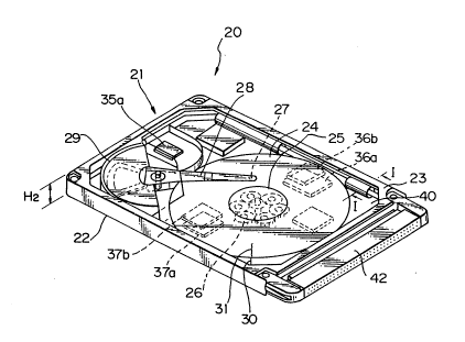
Figs. 3, 4, 5, 6, 7, 8 and ~ are views showing a
first preferred embodiment of a disk drive structure
according to the present invention. To be more specific,
Fig. 3 is a perspective view showing an outer appearance
of a magnetic disk drive and the dimensions thereof;
Fig. 4 is a perspective view partially showing the
construction within a housing; Fig. 5 is a schematic
diagram separately showing a circuit assembly and a
mechanical assembly illustrated in Fig. 4 separately;
Fig. 6 is an exploded perspective view showing the
construction of Fig. 4 in more detail; Fig. 7 is a
sectional front view of Fig. 4; Fig. 8 is an enlarged
sectional view taken along a line I-I of Fig. 4; and
Fig. 9 is an enlarged sectional view taken along a
line II-II of Fig. 6.
In the first preferred embodiment, as illustrated in
these figures, a magnetic disk drive 20 comprises a
single rectangular housing 21 that is constituted from a
base at the lower side and a cover at the upper side.
Further, the housing 21 has outer dimensions in plane
directions of approximately 85.6 mm x 54 mm and has a
; thickness of less than 8 mm, typically 5 mm or 3.3 mm;
namely, the above magnetic disk drive 20 can have the
same size as that of the currently used IC memory card of
type II of PCMCIA.
In this case, unlike the prior art as shown in
Figs. 1 and 2, one magnetic disk 24 preferably having a
diameter of 48 mm or 1.89 inches that stores information,
-- 19 --
a disk driving means 15 that forces the magnetic disk to
rotate, a head assembly that performs read/write
operations on the magnetic disk 24, and electronic
circuitry that is composed of electronic components 70
are contained in a closed space within the above single
housing 21.
Further, the above disk driving means 15 has a
spindle motor 26 that is located at the inner portion of
the magnetic disk 24 so that the magnetic disk can rotate
and a fixed shaft 25 of spindle that is fixed in a
predetermined position within the housing 21 so as to
support the magnetic disk 24 rotatably.
Furthermore, the above head assembly has at least
one magnetic head 27 that executes reproducing/recording
operations corresponding to read/write operations of the
information on either surface of the upper and lower
surfaces of the magnetic disk 24, at least one arm 28
that supports the magnetic head 27, and an actuator 29
that forces the arm 28 to rotate in either direction and
the magnetic head 27 to move to the predetermined track
on the magnetic disk 24. -
Further, in some other preferred embodiments, a head
with a small pressing load is utilized as the above
magnetic head. For example, when the contact type
magnetic head, disclosed in Japanese Unexamined Patent
Publication (Kokai) No. 3-178017 is utilized as the
magnetic head 27, an extremely small load of several tens
of mg can be used. On the other hand, in the flying type
head as shown in Figs. 4 to 7, it is possible for a head
with a relatively small load of several hundreds of mg to
be utilized. Further, by applying the negative pressure
~;~ type head slider and load/unload mechanism to the disk
drive according to the present invention, the friction of
the head, caused when a spindle motor starts up, can be
substantially neglected. By virtue of such advantages, a
spindle motor, that starts up with a relatively low power
voltage, can be realized.
.:: . ~ , ~ . . ; . . - , ,
, " ,.
5. . I . . ,' , ' ~ " . . , , ' ,
- 20 -
~1~0157
Furthermore, the above electronic circuitry includes
an interface circuit 39 that allows communication with an
external host computer, a read/write circuit 36 that
receives read siynals from the head assembly and provides
write signals to the head assembly, a servo circuit that
is comprised of a positioning circuit 37 and an
amplifying circuit (head IC) 35 to control the operations
of the magnetic disk 24 and the head assembly, and a
control circuit 38 that receives control signals Sc from
the external host computer via the interface circuit 39
and provides the control signals Sc to the read/write
circuit 36 and the servo circuit. More specifically, the
control signals Sc and address signals S~ are sent from
the host computer to the interface circuit 39 via the
connector 42. Further, the control signals Sc are input
into the control circuit 38, and status signals S9
indicating the current status of the magnetic disk
drive 20 are issued from the control circuit 38 to the
interface circuit 39. Also, the interface circuit 39 is
coupled to the positioning circuit 37, which determines
the position of the magnetic head 27 on the magnetic
disk 24 in accordance with instructions from the host
computer. Here, the information of the above position
read by the magnetic head 24 is sent back to the
positioning circuit 37 as position signals Sp, via the
amplifying circuit 35, so that accurate positioning can
be performed by means of servo control. Further, power
is supplied to all the above circuits via the
connector 42, together with any other associated
circuits.
Hereinafter, with regard to the various signals in
the interface circuit in the present invention, some
additional explanation will be given. As the
specifications of the interface utilized for the
connector 42, the following specifications can be used;
namely, SCSI (Small Computer System Interface), IDE (or
,. ' , , . : '. ~' ,,, ' : ' ' ., ' ' ' ,
- 21 -
~1001~7
PC/AT) and PCMCIA-ATA(AT Attachment) that will be
standardized in the near future. Among these interface
specifications, with regard to SCSI and IDE, in
particular, their electrical specifications are different
from the electrical specifications of the IC memory card
fabricated in accordance with PCMCIA. Accordingly, it is
impossible for a disk drive fabricated in accordance with
SCSI or IDE, and the above IC memory card to be used in
common. On the other hand, since PCMCIA-ATA provides an
extended function of PCMCIA PC ~ard Standard, a disk
drive fabricated in accordance with PCMCIA-ATA and a disk
drive fabricated in accordance with usual PCMIA can be
inserted into the same slot of a host computer.
Therefore, in preferred embodiments, the PCMCIA-ATA can
be recommended as the interfaces of choice.
Furthermore, a power supply voltage of preferably
3 - 3.3V, should be used. In conventional electronic
circuits, power consumption can be reduced by operating
the circuits at a relatively low voltage. An IC memory
operative at a lower voltage can be obtained due to the
recent progress in the design of electronic circuits.
However, the decreasing of a voltage supplied to
mechanical components does not always lead to a reduction
in power consumption. On the contrary, in such a case,
the ratio of power consumption of electronic circuits for
driving the mechanical components to power consumption of
the mechanical components per se is likely to be rather
increased. The main designs for effectively decreasing
applied voltage are as follows. First, a spindle motor
can be improved and therefore the start-up operation at a
lower voltage can be realized. Second, the diameter of
bearing means can be made smaller and therefore a load
torque can be reduced. Third, a head with a lower
pressure load can be adopted and therefore a load torque
3S during start-up operation can be reduced. Fourth, a
housing made of metal including iron can be adopted and
therefor shielding against various electrical noises can
,
,, . . : ~ ~ , ,
. . : :~ -
. ;. : .
be improved.
Furthermore, as shown in Fig. 6, a plurality of
insertion guide portions 50 are provided on predetermined
portions of the respective sides having longer dimensions
of the housing 21. The above insertion guide portions 50
are intended to allow the housing 21 to be inserted into
a slot of a host computer so that the disk drive can be
placed in an operative condition, if the respective
connectors of the host computer and disk drive are
connected with each other. These insertion guide
portions 50 are constructed to have a thickness of less
than the whole thickness of the housing 27.
As apparent from Fig. 7, the disk 24 is located
approximately in the central position in respect to the
thickness direction of the housing 21. Accordingly,
there exists a flat space 30 between the disk 24 and the
base 22, and another flat space 31 between the disk ~4
and the cover 23.
In the vicinity of the arm 28 in the space 30, an
IC 35a is incorporated, that constitutes a first stage
amplifying circuit 35 for amplifying very small read
signals reproduced by the magnetic head 27. Further, in
the space 30, ICs for processing analog signals, e.g., an
IC 36a that constitutes a part of the read/write
circuit 36 and an IC 37a that constitutes a part of the
positioning circuit 37, are also incorporated.
On the other hand, in a space 31 that is positioned
on the opposite side of the space 30 with respect to the
disk 24 and is separated from the space 30 by the
disk 24, ICs for processing digital signals, e.g., an
IC 36b that constitutes the remaining part of the
read/write circuit 36, an IC 36b that constitutes the
remaining part of the positioning circuits 37, an IC 38a
that constitutes the control circuit 38 and an IC 39a
that constitutes the interface circuit 38 are
incorporated.
All the electronic components 70 that include the
.
- - 23 - ~i ~01~7
above-mentioned ICs 36a - 39a are assembled o~ the
respective surfaces of a first body portion 40a and a
second body portion 40b of a printed circuit board 14,
which are attached close to the inner wall surfaces of
the base 22 and cover 23, respectively, and the above
electronic components 70 are contained within the
housing 21, together with the printed circuit board 14.
Preferably, the above printed circuit board (PCB) 14 is a
flexible printed circuit board (FPC) 40 that is bent into
the lower first body portion 4Oa and the upper second
body portion 40b. In this case, the above flexible
printed circuit board 40 has two bands of connecting
portions 40c, 40d by which the lower first body
portion 40a and the upper second body portion 40b are
coupled with each other. Hereinafter the reason why the
longer side of the housing 21 is selected as the bent
portions (the connecting portions) of the FPC40 in which
the upper and lower portions thereof are integrated with
each other, will be explained in detail. As illustrated
in Figs. 4 and 6, FPC circuit patterns at the upper and
lower sides are connected on the FPC. ~he signalæ flow
from the magnetic head through the connector, via the
head IC, demodulation circuit (analog) in the read/write
circuit and digital processing circuit. As described
above, in view of the analog circuit portion and digital
circuit portion being separated between the lower side
and upper side of the FPC., respectively, the signals
output from the demodulation circuit and the control
signals are arranged to pass through the connecting
portions. As the position where these connecting
portions are located, both the shorter sides and longer
sides of the housing may be selected. Also as described
above, the connector is attached to one of the shorter
sides, while the head actuator is located in the vicinity
of one of the shorter sides. Accordingly, if the upper
and lower sides of the FPC are connected with each other
in the shorter side, they must be connected at the side
.. . . . . . . .
. : , , - :
., : .
- 24 -
;~1001~7
of the head actuator. Such a connecting structure is
disadvantageous in that the overall path for the signals
becomes longer. On the contrary, if the upper and lower
sides of the FPC are connected with each other in the
S longer side, the above-mentioned signal flow can be
realized without any difficulties in arranging circuit
patterns. However, when a disk with a diameter of 4.8 cm
(1.87 inches) is incorporated inside a housing of memory
card size, the disk is likely to protrude outside the
housing and strike the longer sides of the housing. To
avoid this problem, a part of the connecting portions
where the disk protrudes outside the housing is cut out.
In such a construction, the connecting portions can be
reasonably located at the longer side of the housing. In
this case, it is advantageous that the connecting
portions are separated into two parts as shown in Fig. 6,
so that the elastic force that is generated in the
connecting portions when the FPC is bent back, can be
reduced.
As illustrated in Pig. 8, the above connecting
portions 40c (40d) are located across the base 22 and
cover 23. Further, when the housing 21 is in a closed
condition such that the cover 23 covers over the base 22,
the connecting portions 40c (40d) are curved so that they
protrude inside the housing 21 as shown in Fig. 9. As
apparent from Fig. 9, since the connecting portions are
constructed to have excess length, it becomes possible
for the base 22 and cover 23 to be arranged in plane
directions and for the various components to be
~; ~ 30 incorporated inside the housing 21. As the excess length
of the connecting portions becomes large, the components
can be incorporated more easily, while the protruding
parts formed by this excess length are likely to
interfere with the disk 24 and the other mounted
components. To avoid this difficulty, it is proposed
that these protruding parts be bent back further so that
they are folded together in multiple layers. More
~:
- 25 -
~001~7
concretely, in the condition that the base 22 and
cover 23 are arranged in plane directions, such a folded
structure can be realized by forcing down the center of
the bridge portion of the FPC40 with a wire. In the
condition that the base 22 is overlaid with the cover 23,
the cover 23 adheres closely to the base 22 via a
packing 41, and therefore the whole space within the
housing 21 where the disk, etc., are contained is closed
up tightly. In this case, to reduce the pressure
difference between the inside and outside of the housing
caused by the temperature rise during operation of the
disk drive, an air filter for circulation is attached to
the housing. In that sense, it cannot always be said
that the space within the housing is perfectly closed up.
However, dust in the air can be prevented from entering
the housing. Therefore, the structure, in which the air
filter is provided, is also usually referred to as a
tightly closed structure.
Further, the connector 42 is attached to either one
of two sides having shorter dimensions of the housing 21.
Here, the above connector 42 is located in a position
opposite to the actuator 29 across the disk 24 and is
located in the approximately central position in respect
to the thickness direction of the housing 21, so that
mechanical support of the whole disk drive can be
achieved by means of the connector 42 with good balance
of weight.
The magnetic disk drive of the present invention
does not incorporate a vibration-free support mechanism
that is employed in general devices, but employs a
mechanical support using a connector which makes a
~ feature.
; The connector which has as many as 68 pins produces
a considerably large holding force but still
consideration must be given to cope with the disturbance.
The disturbance which is internally generated stems from
(1) vibration due to the unbalanced spindle and (2) seek
,~ ~
`:
- 26 -
`` ~1001~7
reaction of the actuator. Furthermore, external
vibration and shocks are added thereto. Here, first,
countermeasure is taken against the above two causes of
internal generation.
S First, vibration due to the unbalanced spindle
generates while the spindle is revolving and becomes a
cause of error in position. Therefore, attention is
given in an effort to minimize the amount of residual
imbalance, and support conditions are contrived too to
reduce the effect. ~enerally speaking, the vibration due
to imbalance is determined by a moment of the center of
rotation of the spindle and the center of gravity or the
distance of the fulcrum. In the present invention which
accomplishes the support using the connector, therefore,
the spindle is disposed on a side close to the connector
and the actuator is disposed on a side remote from the
connector. The moment that is generated can be decreased
by about 40% compared with that of the constitution
fabricated in an opposite manner, and the error in
position due to the ~ibration of imbalance can be
decreased by 40%. When completely balanced, only the
moment of rotation generates which does not change
irrespective of the position of the actuator. In
principle, therefore, there arises no adverse effect even
when the actuator is disposed on the side remote from the
connector.
To cope with the reaction of the actuator, first,
the connector accomplishes the linear support; i.e.,
considerably rigid support is accomplished in the
direction of rotation to suppress the rotary motion of
the whole drive caused by the moment generated by the -
actuator thereby to suppress the error in position caused
;;~ by the turn of the drive. The connector is disposed at
the center in the thickness direction of the drive and,
further, the center of gravity of the actuator is brought
into this position, so that there takes place no motion
due to the seek reaction (moment) in the up-and-down
.
- 27 - ~ ~0 1~7
direction or in the twisting direction. This makes it
possible to suppress error in position, fluctuation of
floatation, etc. caused by the motion in the directions
outside the planes.
More concretely, the connector 42 is fixed on the
cover 23 of the housing 21 and is connected to the second
body portion 40b of the FPC 40, on which the digital
electronic components such as the IC 39a of the interface
circuit 39 are assembled. Further, a par o of the second
body portion 40b, that is connected to the connector 42,
is covered with the packing 41.
A similar construction of the above-mentioned disk
drive has been disclosed in Japanese Unexamined Patent
Publication (Kokai) No. 60-242568. However, in such a
known construction, it is not described clearly that all
the electronic components including analog and digital
components are incorporated within a single housing,
unlike the above first preferred embodiment.
On the contrary, the disk drive having the
construction according to the present invention as
illustrated in the first preferred embodiment is intended
to accommodate all the electronic components, as well as
the disk and various mechanical components by utilizing
the spaces within a single housing effectively.
Consequently, the disk drive 20 can have a single housing
structure and can have a thickness dimension of
approximately 5 mm which is the same as that of an
IC memory card of the above-mentioned type II of PCMCIA.
Therefore, the disk drive 20 becomes thinner and more
compact than any disk drive according to a prior art, and
it can be more easily used for a portable computer than
the prior art disk drive.
Furthermore, since the connecting portions 40c, 40d
are previously formed in the above-mentioned FPC 40, it
becomes unnecessary to provide a connector component for
connecting two body portions 40a, 40b to each other.
Owing to the above advantage, the disk drive 20 can have
i
.'; ' - ~ ~ .,~ .
0 ~ 5 7
an even thinner dimension as desired for a suitable and
portable memory device.
As described above, the construction of the disk
drive in the first preferred embodiment has also the
following features.
First, an analog circuit portion for processing
analog signals and a digital circuit portion for
processing digital signals are separated from each other
at the lower side and upper side of the housing,
respectively.
Second, a substrate of the disk, that is generally
made of metal including aluminum, is loca~ed between the
above two separated circuit portions; nam~ly, the disk
substrate has a function of electromagnetically shielding
the above two circuit portions from each other.
In such a construction, it becomes possible for
analog signals in the analog circuit portion to be
prevented from suffering negative influence due to
electromagnetic waves generated by the digital circuit
portion. In other words, the disk drive in the first
preferred embodiment has a structure in which a counter
measure against various electric noises cab be taken
without increasing the thickness dimension of the disk
drive. In this case, it will be also possible in the
future for the thickness of the disk drive to be reduced
to 3.3 mm which is the same as that of the type I of
PCMCIA I~ memory card.
Further, since the structure of such a disk drive is
resistant to electric noises, a disk drive operative at a
lower power supply voltage can be realized and power
consumption in the disk drive can be reduced.
Fig. 10 is a view showing a second preferred
embodiment of a disk drive structure according to the
present invention. To be more specific, Fig. 10 is a
sectional front view showing the main part of a disk
drive relating to the second preferred embodiment of the
present invention. From now on, any component that is
.' . . . . . . .
- 29 -
~10()1~7
the same as a component mentioned before will be referred
to using the same reference number.
In the second preferred embodiment shown in Fig. 10,
metal based printed circuit boards 91, 92 are utilized
instead of the flexible printed circuit board 40 in the
first preferred embodiment described above. As
illustrated in Fig. 10, both of a base 22 and a cover 23
are made of metal including iron, and on the respective
inner wall surfaces of the base 22 and cover 23, the
metal based printed circuit boards 91, 92 are directly
formed, respectively. Further, ICs 35a - 39b (in
Fig. 10, only IC 38a is shown) are directly assembled on
the metal based printed circuit boards 91, 92.
According to the second preferred embodiment, it is
unnecessary for the printed circuit board to be adhered
to the inner wa~l surfaces of the base 22 and cover 23.
Therefore, the above second preferred embodiment has an
advantage in that the sequences for assemblinq electronic
components become simpler than the assembling sequences
in the first preferred embodiment.
Fig. 11 is a view showing a third preferred
embodiment of a disk drive structure according to the
present invention. To be more specific, (A) of Fig. 11
is a simplified top view and (B) of Fig. 11 is a
simplified front view, showing the characteristics of the
third preferred embodiment.
As illustrated in (A) and (B) of Fig. 11, a
supplementary shielding sheet 61 is provided in a form
such that a surrounding region outside the disk 24 and
inside the base 22 and cover 23 is covered with the above
supplementary shielding sheet 61. In this construction,
; the lower analog circuit portion and the upper other
digital circuit portion within the housing 21 as in
Fig. 7 can be separated electromagnetically from each
other. The third preferred embodiment as shown in
Fig. 11 can be effectively applied in a case where the
whole region where the analog and digital circuit
; ~ 30 ~ ~1001~7
portions within the housing 21 are located cannot be
completely covered with the disk 24 alone.
Fig. 12 is a view showing a fourth preferred
embodiment of a disk drive structure according to the
present invention. To be more specific, (A) of Fig. 12
is a simplified top view and (B) of Fig. 12 is a
simplified front view, showing the characteristics of the
fourth preferred embodiment.
As illustrated in (A) and (B) of Fig. 12, first and
second shielding walls 71, 72 each having the form of a
rib are formed inside the base 22 and cover 23,
respectively. The first shielding wall 71 at the side of
the base 22 is located between the IC 36a and IC 37a.
This first shielding wall 71 serves to prevent a
reproducing/recording circuit block and a positioning
circuit block, both analog circuit portions, from
interfering with each other. Further, the second
shielding wall 72 at the side of the cover 23 is located
between the IC 36b and IC 37b. This second shielding
wall 72 serves to prevent a reproducing/recording circuit
block and a positioning circuit block, both digital
circuit portions, from interfering with each other,
; similar to the first shielding wall 71. In other words,
the above first and second shielding walls 71, 72 are
constructed such that the analog circuit portion and the
digital circuit portion are partitioned among individual
function blocks, respectively. In such a construction,
it can be ensured that electromagnetic shielding is
performed more efficiently than the shielding in the
; 30 third preferred embodiment shown in Fig. 11.
Fig. 13 is a view showing a fifth preferred
embodiment of a disk drive structure according to the
present invention. To be more specific, (A) of Fig. 13
is a simplified top view and (B) of Fig. 13 is a
simplified front view, showing the characteristics of the
fifth preferred embodiment.
As illustrated in (A) and (B) of Fig. 13, first
1~ ~
.. . ... . .. . .
, . ! . ' , .; ~ ~ . ~ , .
~' - 31 - ~ 157
shielding wall parts 81 and second shielding wall
parts 82 each having the form of a rib protrude toward
the disk 24 inside the base 22 and cover 23,
respectively. More concretely, the first and second
shielding wall parts 81, 82 are formed along the boundary
of a region within which the magnetic head 27 moves. In
such a construction, the magnetic disk 27 and the IC 35a
constituting the first stage amplifying circuit, that are
most likely to suffer influence due to various electric
noises, can be protected from electromagnetic waves
generated by the other circuit portions.
Fig. 14 is a view showing a sixth preferred
embodiment of a disk drive structure according to the
present invention. To be more specific, Fig. 14 is a
lS sectional front view showing the main part of a disk
drive relating to the sixth preferred embodiment of the
present invention.
In Fig. 14, the flexible printed circuit board 90 is
preferably used as a printed circuit board 14 (Fig. 6).
This flexible printed circuit board 90 has a double
structure in which circuit patterns 90b-1 r 90b-2 are
formed on one surface of a film substrate 90a, while
overall earth patterns 90c-1, 90c-2 are formed on the
other surface of the film substrate 90a excluding bent
portions thereof. Further, the above flexible printed
circuit board 90 is provided along the inner wall of the
housing 21. In this case, the circuit patterns 90b-1,
90b-2 face the inner wall surfaces of the bases 22 and
cover 23, respectively, while the overall earth patterns
90c-1, 90c-2 face the lower and upper surfaces of the
disk 24, respectively.
Further, in Fig. 14, ICs 36a, 37a are assembled on
the circuit patterns 90b-1 of the flexible printed
circuit board 90, and are adhered closely to the inner
wall of the base 22. On the other hand, ICs 36b, 37b,
38a and 39a are assembled on the circuit patterns 90b-2
of the flexible printed circuit board 90, and are adhered
- 32 -
~lOOlS7
closely to the inner wall of the cover 23. On the
surface of the base 22 and cover 23, heat radiating fins
22Ba, 23sa are formed. Respectively, by virtue of the
above heat radiating fins 22Ba, 23Ba, the heat generated
S by the ICs 36a - 39a can be effectively radiated through
the base 22 and cover 23 to the ou~side of the
housing 21.
Here, it is assumed that electromagnetic waves are
generated from the circuit pattern 90b-2 dealing with
digital signals and are directed toward the other circuit
patt~rn 90b-l dealing with analog signals. In the
construction of the sixth preferred embodiment, the above
circuit pattern 90b-1 can be effectively shielded from
the electromagnetic waves by means of the overall earth
patterns 90c-1, 90c-2, as well as the disk 24.
Further, a portion 9OA of the flexible printed
circuit board 90, that is placed near the magnetic
head 27, represents the portion on which an IC 35a is
assembled. In respect to the portion 90A, the circuit
pattern 90b-1 is formed on the surface opposite to the
surface of the other portion of circuit pattern 90b-1 by
utilizing through holes 90d. Consequently, the IC 35a
can be located in the vicinity of the magnetic head 27.
In such a construction, the electrical path from the
magnetic head 27 through the IC 35a becomes shorter, and
therefore the reproducing signals (read signals) are less
apt to suffer influence due to external disturbances,
such as electrical noises.
Figs. 15, 16, 17, 18 and 19 are views showing a
seventh preferred embodiment of a disk drive structure
according to the present invention. To be more specific,
Fig. 15 is a perspective view showing the inside of a
magnetic disk drive; Fig. 16 is an exploded perspective
view showing the construction of Fig. 15 in more detail;
Fig. 17 is a sectional view taken along a line III-III of
Fig. 15; Fig. 18 is an enlarged perspective view showing
a portion of Fig. 16 enclosed within a circle A; and
33 ~ 1~ 01.~ 7
Fig. 19 is an enlarged perspective view in which a
portion of Fig. 15 enclosed within a circle B is seen
from the side shown by an arrow V.
In these figure, 40-1 denotes a first printed
circuit board element preferably made of a flexible
printed circuit board on which an IC 37a, etc., is
assembled. The above first printed circuit board
element 40-1 is placed on the inner wall surface 2A-1 of
a base 22 made of metal, adhering to the above inner wall
surface 2A-1 thereof. In this case, the reference
numerals of ICs other than IC 37a and IC 37b (referred to
hereinafter) are omitted to simplify the explanation of
Figs. 15 to 19.
Further, the first printed circuit board
element 40-1 has two tongue portions 21-3, 21-4 that are
projected outward one side 21-1 of a pair of two longer
sides 21-1, 21-2 positioned along the longer direction of
the above first printed circuit board element 40-1, and
has a portion 21-5 that is projected outward from the
other side 21-2 thereof. Furthermore, this first printed
circuit board element 40-1 has a tongue portion 21-7 that
is projected outward from one shorter side 21-6 of the
above first printed circuit board element 40-1. On the
tongue portions 21-3, 21-4, 21-5 and 21~7, a plurality of
terminals 22-1, 22-2, 22-3 and 22-4 are formed,
respectively.
The base 22 includes a rib-shaped first fringe
portion 2A-2 having a rectangular frame form over the
;~ whole circumference of the above base 22. Further, the
above first fringe portion 2A-2 comprises a pair of
longer sides 2A-2-1, 2A-2-2 and a pair of shorter sides
~ 2A-2-3, 2A-2-4. Preferably, the upper surface 2A-2a of
; this fringe portion 2A-2 has a flat face.
Further, as illustrated enlarged in Fig. 18 shallow
recessed parts 2A-2b, 2A-2c and 2A-2d are formed in the
predetermined positions of the longer sides 2A-2-l,
2A-2-2 on the upper flat surface 2A-2a of the fringe
'., .. : ' ": ' .' ' ' :, '',: : : .'':. ' ' ' ' ' . ' . .. , ' : ' , ,
-~ - 34 -
~ ~ 001~7
portion 2A-2, while another shallow recessed part 2A-2e
is formed in the predetermined positions of one shorter
side 2A-2-3 thereon.
Also in Fig. 18, the above tongue portions 21-3,
21-4, 21-5 and 21-7 are constructed to rise up once along
the first fringe portion 2A-2 and further to be bent
outward from the firs~ fringe portion 2A-2. Furthermore,
the tongue portions 21-3, 21-4, 21-5 and 21-7 are
projected on the longer sides 2A-2-1, 2A-2-2, and the
shorter side 2A-2-3 and finally are contained in the
shallow recessed parts 2A-2b, 2A-2c, 2A-2d and 2A-2e.
The terminals 22-1 - 22-4, i.e., a first group of
terminals, are located so that they are exposed on the
upper surface 2A-2a of the first fringe portion 2A-2.
Further, in Figs. 15 to 19, 40-2 denotes a second
printed circuit board element preferably made of a
flexible printed circuit board on which an IC 37b, etc.,
is assembled, similar to the second printed circuit board
element 40-1. The above second printed circuit board
element 40-2 is placed on the inner wall surface 3A-1 of
a cover 23 made of metal, and adhered to the above inner
wall surface 3A-l thereof.
Furthermore, the second printed circuit board
element 40-2 has two tongue portions 20-3, 20-4 that are
projected outward from one side 25-1 of a pair of two
longer sides 20-1, 20-2 positioned along the longer
direction of the above second printed circuit board
element 40-1, and has a portion 20-5 that is projected
out~ard from the other side 20-2 thereof. Furthermore,
this second printed circuit board element 40-2 has a
tongue portion 20-7 that is projected outward from one
shorter side 20-6 of the above second printed circuit
board element 40-2. On the tongue portions 20-3, 20-4,
20-5, and 20-7, a plurality of terminals 23-1, 23-2, 23-3
and 23-4 are formed, respectively.
The cover 23 includes a rib-shaped second fringe
port.ion 3A-2 having a rectangular frame form over the
.
::
~:
- 35 -
~ 001~7
whole circumference of the above cover 23. Further, the
above second fringe portion 3A-2 comprises a pair of
longer sides 3A-2-1, 3A-2-2 and a pair of shorter
sides 3A-2-3, 3A-2-4. Preferably, the upper
surface 3A-2a of this fringe portion 3A-2 has a flat
face.
Further, similar to the construction relating to the
first fringe portion 2A-2 described above, shallow
recessed parts 3A-2b, 3A-2c and 3A-2d are formed at
predetermined positions of the longer sides 3A-2-1,
3A-2-2 on the upper flat surface 3A-2a of the fringe
portion 3A-2, while another shallow recessed part 3A-2e
is formed at a predetermined position of one shorter
side 3A-2-3 thereon.
The above tongue portions 20-3, 20-4, 20-5 and 20-7
are constructed to rise up once along the second fringe
portion 3A-2 and further to be bent outward from the
second fringe portion 3A-2. Furthermore, these tongue
portions 20-3, 20-4, 20-5 and 20-7 are projected on the
longer sides 3A-2-1, 3A-2-2 and the shorter side 3A-2-3
and finally are contained in the shallow recessed
parts 3A-2b, 3A-2c, 3A-2d and 3A-2e. The
terminals 23-1 - 23-4, i.e., a second group of terminals
are located such that they are exposed on the upper `
surface 3A-2a of the second fringe portion 3A-2.
Further, in this construction, a fixed shaft 25 of a
spindle, a magnetic disk 24, at least one magnetic
head 27, at least one arm 28, an actuator 29 and the like
; are assembled inside the base 22, and then the cover 23
is arranged in a predetermined position on the base 22 in
such a manner that the base 22 is covered with the
cover 23. Furthermore, the upper surface 2A-2a of the
first fringe portion 2A-2 and the upper surface 3A-2b of
; the first fringe portion 3A-2 are fixed together over the
whole circumference by utilizing an anisotropic
conductive adhesive 32.
In the condition that the cover 23 is combined with
- 36 - ~ l 001 ~ 7
the base 22 as described above, the second tongue
portions 20-3, 20-4, 20-5 and 20-7 in the cover 23 face
the first tongue portions 21-3, 21-4, 21-5 and 21-7 in
the base 22, respectively, and the second group of
terminals 23-1 - 23-4 face the first group of
terminals 22-1 - 22-4, respectively. Consequently, as
illustrated in Fig. 17, the above second tongue
portions 20-3, 20-4, 20-5 and 20-7 are arranged so as to
be contained in the shallow recessed parts 2A-2b, 2A-2c,
2A-2c and 2A-2d of the base 22, respectively, while the
above first tongue portions 21 3, 21-4, 21-5 and 21-7 are
arranged to be contained in the shallow recessed
parts 3A-2b, 3A-2c, 3A-2c and 3A-2d of the cover 23,
respectively. In such an arrangement, the second tongue
portions 20-3, 20-4, 20-5 and 20-7 and first tongue
portions 21-3, 21-4, 21-5 and 21-7 are firmly fastened
together by means of the anisotropic conductive
adhesive 32. ~ere, all the tongue portions 20-3, 20-4,
20-5, 20-7, 21-3, 21-4, 21-5 and 21-7 can be held in the
respectively corresponding shallow recessed parts 2A-2b,
3A-3b, etc., and therefore the above tongue
portions 20-3, 21-3, etc., have no disadvantageous
influence on the respective adhering surfaces of the
cover 23 and base 22. Therefore, the first and second
fringe portions 2A-2, 3A-2 can be adhered to each other
in such a manner that the first fringe portion 2A-2 is
substantially perfectly glued to the second fringe
portion 3A-2 over the whole circumference thereof.
Further, as illustrated in Fig. 19, the anisotropic
conductive adhesive 32 has electrically conductive
characteristics in respect to the direction of the
Z-axis, i.e., in the direction where this anisotropic
conductive adhesive 32 is pressed between two tongue
portions, while it does not have any electrically
conductive characteristics in respect to the direction of
the X-axis and Y-axis. Consequently, the terminal 23-1
of the cover 23 and the corresponding terminal 22-1 of
. , . . . . . . :
,:. -. . - ,, ~ ~
. . . . . . .
~ 37 - ~ i 0 0 1 ~ 7
the base 22 can be electrically connected to each other.
Further, electrical connections ~an be performed between
the other terminals 23-2, 23-3 and 23-4 of the cover 23
and the respectively corresponding terminals 22-2, 22-3
and 22-4 of the base 22 in a similar manner.
In the seventh preferred embodiment described above,
the whole circumference of the fringe portions 2A-2, 3A-2
are coated with the anisotropic conductive adhesive 32.
However, alternatively, it is possible for only the
respective tongue portions in the base 22 and cover 23 to
be coated with the anisotropic conductive adhesive 32, or
it is also possible for the fringe portions 2A-2, 3A-2
and the tongue portions to be partially coated with the
anisotropic conductive adhesive 32.
In this case, since the printed circuit board is
separated into two different elements respectively
corresponding to the base 22 and cover 23, the above
base 22 and cover 23 can be treated independently.
Therefore, the seventh preferred embodiment has an
advantage in that the process for assembling the magnetic
disk 24, the spindle 25, the magnetic head 27 and the
like inside the housing 21 becomes relatively simple.
Further, since all the tongue portions are held in
respectively corresponding shallow recessed parts, the
base 22 and cover 23 can be fixed together closely by
means of the anisotropic conductive adhesive 32 over the
whole circumference. Therefore, the seventh preferred
embodiment has another advantage in that a sufficiently
closed condition within the housing 21 can be ensured.
Fig. 20 is a view showing one example of a change in
the enclosure part of tongue portions in the seventh
preferred embodiment as illustrated in Fig. 17. In
Fig. 20, the structure inside the housing 21 is
illustrated more briefly to simplify the explanation.
As shown in Fig. 20, at least one concave stepped
part 33' is provided as the enclosure part of tongue
portions only at the side of the cover 23, unlike the
,. . - : .~ : . . - . . ~
..
- 38 -
~ ~ ~ U 1 ~ 7
construction of Fig. 17. Further, in Fig. 20, the
respective tongue portions 21-1, 20-1 in the base 22 and
cover 23 are contained in a space between the above
recessed stepped part 33 and the upper surface 2A-2a of
the fringe portion 2A-2 of base 22, in a condition such
that the respective tongue portions 21-1, 20-1 in the
base 22 and cover 23 overlap each other.
Fig. 21 is a view showing another example o~ a
change in the enclosure part of tongue portions in the
seventh preferred embodiment as in Fig. 17. Also in
Fig. 21, similar to Fig. 20, the structure inside the
housing 21 is illustrated more briefly to simplify the
explanation.
As shown in Fig. 21, at least one convex part 34 is
provided as the enclosure part of tongue portions in the
fringe portion 3A-2 of the cover 23, unlike the
construction of Fig. 17. Further, in Fig. 20, the
respective tongue portions 21-1, 20-1 of the base 22 and
cover 23 are contained in a space between the above
convex part 34 and the inner wall surface 2A-l of the
base 22, in a condition such that the respective tongue
portions 21-1, 20-5 of the base 22 and cover 23 overlap
each other.
Fig. 22 is a view showing an eighth preferred
embodiment of a disk drive structure according to the
present invention. In Fig. 22, the main part of the
structure inside the housing 21 is illustrated.
As shown in Fig. 22, the base 22 and cover 23, that
are made by press forming a metal plate, have flange
portions 2Ba, 3Ba in the circumferences of the above
base 22 and cover 23, respectively. Further, in Fig. 22,
the respective tongue portions 21-3, 20-3 of the flexible
printed circuit board elements 40-1, 40-2 are coated with
the anisotropic conductive adhesive 32 and are held
between the above two flange portions 2Ba, 3Ba. Finally,
the base 22 and cover 23 are fixed together by applying a
pressure F on the flange portions 2Ba, 3Ba and adhering
- 39 -
~l~Ol!a7
them to each other.
Fig. 23 is a view showing a ninth preferred
embodiment of a disk drive structure according to the
present invention. Also in Fig. 23, similar to Fig. 22,
the main part of the structure inside the housing 21 is
illustrated.
As shown in Fig. 22, the base 22 and cover 23, that
are made by press forming a metal plate, have other
flange portions 2Ca, 3Ca in the circumferences of the
above base 22 and cover 23, respectively. Here, the
dimension of the overhang of one flange portion 2Ca is
twice as long as that of the overhang of the other flange
portion 3Ca. First, the respective tongue portions 21-3,
20-3 of the flexible printed circuit board elements 40-1,
40-2 are coated with the anisotropic conductive
adhesive 32 and are held between the above two flange
portions 2Ca, 3Ca. Next, the former flange portion 2Ca
is folded back in such a manner that it covers the latter
flange portion 3Ca, and a bent portion 2Ca-1 is formed at
the upper side of the flange portion 3Ca as illustrated
in Fig. 23. Finally, the base 22 and cover 23 are
adhered together by applying a pressure F to the flange
portion 2Ca and the bent portion 2Ca-l and by fitting the
inner flange portion 3Ca into the outer flange
portion 2Ca. In this construction, fitting and adhering
of the flange portions are simultaneously performed, so
the electronic components such IC 37a, 37b can be tightly
enclosed in the housing 21 with higher reliability.
Figs. 24 and 25 are views showing a tenth preferred
embodiment of a disk drive structure according to the
present invention. To be more specific, Fig. 24 is a
schematic flat view showing the whole disk drive
structure and Fig. 25 is a schematic sectional front view
showing the structure inside the housing.
In these figures, similar to all the other previous
embodiments, one magnetic disk 24 preferably having a
diameter of 48 mm or 1.89 inches, a disk driving
- 40 -
~1001~7
means lS, a head assembly that includes magnetic
heads 27, an actuator 29, etc., electronic circuitry and
a printed circuit board 14 such as a flexible printed
circuit board are contained in a closed space within a
single housing 21, which is constituted by a base 22 and
cover 23 and has the same dimensions as the outer
dimensions of the type II PCNCIA IC memory card. In
Figs. 24 and 25, the connector 42 is omitted.
Further, in the remaining space within the
housing 21 other than a movable space where the magnetic
disk 24, the disk driving means 15, the head assembly and
the other enclosed components as described above can be
moved, a filler 16 having a form corresponding to the
concavity and convexity of the remaining space is placed
in the remaining space. Preferably, the above filler 16
is made of a resin material, such as polycarbonate resin
or epoxy resin.
In this construction, the unoccupied space can be
reduced to the minimum dimensions required. Therefore,
the deformation of the housing 21, that may occur by
applying various external forces thereto, can be easily
prevented, and disadvantageous vibrations of the enclosed
components within the housing 21 can be also avoided.
Fig. 26 is a sectional view showing an eleventh
preferred embodiment of a disk drive structure according
to the present invention. In Fig. 26, only the main part
of the structure inside the housing 21 relating to the
characteristics of the eleventh preferred embodiment is
illustrated.
. .
The construction of the above eleventh preferred
embodiment is similar to that of the tenth preferred
embodiment described before. However, the construction
of the eleventh embodiment is different from that of the
tenth embodiment in the following points:
.
first, the printed circuit board 14 is divided
into a lower printed zircuit board part 14a and an upper
printed circuit board part 14b, that are composed of
~ :
:`
- 41 -
~1~0157
flexible printed circuit board material or thinly-made
printed circuit board material and that are laid separate
from each other on the inner wall surfaces of the base 22
and cover 23, respectively; and,
second, a magnetic material 16-1, that is
fabricated by mixing an adhesive made of resin with a
magnetic powder such as Mn-Zn ferrite, is coated on the
outer peripheral surface of the above-mentioned
filler 16.
Also in the construction of the eleventh preferred
embodiment, similar to that of the tenth preferred
embodiment, the deformation of the housing 21 can be
firmly prevented by virtue of the filler 16. Here, both
of the printed circuit board parts 14a, 14b are usually
located in proximity to the magnetic head, and therefore
electromagnetic noises are likely to leak from these
printed circuit board parts 14a, 14b. Consequently, such
electromagnetic noises are superimposed on
reproducing/recording signals (read/write signals) and
the signal-to-noise (S/N) ratio may be deteriorated.
However, in the construction of the eleventh preferred
embodiment, since the magnetic material 16-1 serves to
electromagnetically shield the electromagnetic noises,
deterioration of the signal-to-noise (S/N) ratio ~an be
avoided.
Fig. 27 is a sectional view showing a twelfth
preferred embodiment of a disk drive structure according
to the present invention. Also in Fig. 27, only the main
part of the structure inside the housing 21 relating to
the char~cteristics of the twelfth preferred embodiment
is illustrated.
The construction of the above twelfth preferred
embodiment is similar to that of the tenth and eleventh
preferred embodiments described before. However, the
construction of the twelfth embodiment is different from
that of the other embodiments in that a conductive filler
16-2, which is formed by forcing a conductive material to
.
"' . " , ~ .. ' . ' . . .
- 42 - ~1001~7
be included in an insulating filler, such as
polycarbonate resin or epoxy resin, is placed in the
above-mentioned space in the housing 21.
Also in the construction of the twelfth preferred
embodiment, similar to that of the eleventh preferred
embodiment, the deformation of the housing 21 can be
firmly prevented by virtue of the conductive filler 16-2.
Further, in the construction of the twelfth preferred
embodiment, since the conductive filler 16-2 also serves
to electromagnetically shield from electromagnetic
noises, deterioration of the signal-to-noise (S/N) ratio
can be avoided, similar to the eleventh preferred
embodiment.
Fig. 28 is a sectional view showing a thirteenth
preferred embodiment of a disk drive structure according
to the present invention. Also in Fig. 28, the main part
of the structure inside the housing 21 is illustrated.
In Fig. 28, an elastic adhering film 16-3 composed
of an elastic adhesive including rubber, etc., is coated
on the outermost peripheral surface of the filler 16.
Further, the filler 16 enclosed with an elastic adhering
film 16-3 is placed in the above-mentioned space in the
housing 21. In this construction, the above filler 16
fits snugly with the base 22, cover 23 and each of the
enclosed components within the housing 21 by virtue the
elastic adhering film 16-3. Therefore, the thirteenth
preferred embodiment has an advantage that the vibrations
~;~ of the above filler 16, which are likely to be generated
during operation of the disk drive, can be surely
prevented.
Fig. 29 is a sectional view showing a fourteenth
; preferred embodiment of a disk drive structure according
to the present invention. Also in Fig. 29, the main part
of the structure inside the housing 21 is illustrated.
In Fig. 29, at least one signaling lead wire 14-1 is
embedded in a filler 16, corresponding to the
predetermined positions of the lower and upper printed
.
: . ..
- 43 ~ ~1001~7
circuit board parts 14a, 14b as described in Fig. 26.
Further, the above filler 16 is placed in the above-
mentioned space, similar to the thirteenth preferred
embodiment, etc. In this construction, similar to the
S tenth preferred embodiment as illustrated in Fig. 25, the
deformation of the housing 21, that may occur by applying
various external forces thereto, can be easily prevented.
Moreover, the wiring connection further necessitated in
the lower printed circuit board part 14a or in the upper
printed circuit board part 14b individually and the ~-
wiring connection between the lower and upper printed
circuit board parts 14a, 14b can be realiæed
simultaneously.
Figs. 30, 31, 32, 33 and 34 are views showing a
fifteenth preferred embodiment of a disk drive structure
according to the present invention. To be more specific,
Fig. 30 is a schematic exploded perspective view showing
an essential construction; Fig. 31 is a schematic
enlarged sectional view showing an essential
construction; Fig. 32 is an exploded perspective view
showing a disk drive structurè in more detail; Fig. 33 is
a perspective view showing the inside of a disk drive;
and Fig. 34 is an enlarged sectional view showing the
main part of a disk drive in more detail.
In the fifteenth preferred embodiment, as
illustrated in these figures, a disk drive 20 comprises a
single thin rectangular housing 21 that is constituted by
a base 22 and a cover 23 and that has outer dimensions of
;~ approximately 85.6 mm x 54 mm x 5 mm which are the same
as an IC memory card of type II of PCMCIA, similar to the
other embodiments described before. More concretely, -
each of the above base 22 and cover 23 are fabricated by
forming a metal plate with a height of 4 to 5 mm by means
of drawing into a form of a vessel. Typically, a height
of the base 22 is 2 mm, while a thickness of the cover 23
is 3 mm. The steel plate with the thickness of
0.4 - 0.5 mm is formed by means of drawing and the
_ 44 ~ ~1uOi~7
base 22 and cover 23 each having an opening in one side
and each having a vessel form. Accordingly, if this
base 22 and cover 23 are combined together, the total
thickness, i.e., a thickness dimension of the rectangular
housing 21, becomes 5 mm.
Hereinafter, the reason why the height of the
base 22 is designed to be different from the height of
the cover 23 will be explained in detail. As described
above, according to the specification of type II of
PCMCIA, both the longer sides of the housing serve as the
insertion guide portion to the host computer, and
therefore the related longer sides are limited to 3.3 mm
in length. Since this portion touches with the outer
peripheral of the disk having a diameter of 1.89 inch,
i.e., 48 mm, it is preferable to dispose the disk at the
center of the width of the housing. Further, in
correspondence with the above arrangement of the disk, it
is required to form a gun barrel shaped recess such as
shown in Flg. 48 to each of the base and cover. Such
complicated drawing reduces the area of a flange surface
and also strength of both the base and the cover and
coupling intensity therebetween. In order to avoid this,
the height of the base is shifted with respect to that of
the cover, and thus thinner one of the flange surfaces
can be surely obtained. Note that it is also preferable
to dispose the disk at the center of the width of the
housing, since the electronic parts, mounted on the inner
walls of the base and the cover, have the same maximum
height at the base side and the cover side.
Further, in one of the shorter sides of the
rectangular housing 21, a space for fixing a connector 42
is provided. In the other shorter side and two longer
sides of the housing 21, as illustrated in Fig. 34,
coupling flanges 12-1, 12-2, extend outward at the outer
peripheral portion of the above base 22 and cover 23,
respectively, in accordance with the characteristics of
the fifteenth preferred embodiment.
,
: - , , . , ~
.
~ 45 ~ ~1~U1~7
The rectangular housing 21 includes at least one
magnetic disk 24, a spindle motor 26, at least one
magnetic head 27, at least one arm 28, an actuator 29,
electronic components 70 and the like, similar to the
embodiments described before, e.g., the first preferred
embodiment shown in Figs. 3 to 9. Here, the actuator 29
comprises a magnet portion 29a composed of at least one
permanent magnet, a yoke portion 29c located in such a
manner that it encloses the permanent magnet, and a
movable coil portion 29b located inside the yoke
portion 29c. In this case, the detailed explanation of
the above disk drive structure other than the portion of
the coupling flanges 12-1, 12-2 is omitted to clarify the
characteristics of the fifteenth preferred embodiment.
As typically shown in Fig. 32, the base 22 is
combined with the cover 23 by overlapping the
respectively corresponding coupling flanges 12-1, 12-2 of
the base 22 and cover 23 with each other. Further, the
coupling flanges 12-1, 12-2 are preferably jointed and
fastened together by spot welding, if both of the base 22
and cover 23 are made of metal including iron.
Alternatively, hermetic sealing to some extent can be
guaranteed if the seam-welding is effected in which spot
welding is continuously carried out. When the base and
the cover are made of a metal other than iron or a resin
material, the coupling flanges are joined together by
such means as wrap-seaming, screws or riveting. Metal
including iron can be joined together by such means, as a
matter of course. Alternatively, if both of the base 22
and cover 23 are made of metal including aluminum or made
of a resin material, these coupling flanges 12-1, 12-2
are preferably jointed and fastened together by screws or
rivets. Further, in the outer peripheral portion of the
above jointed coupling flanges 12-1, 12-2, a frame 13
composed of a pair of L-shaped frame elements 13a, 13b is
attached to force the jointed coupling flanges 12-1, 12-2
to be closed up tightly. Each of these L-shaped frame
- 46 -
01~7
elements 13a, 13b are made of so-called engineering
plastic, e.g., polyamide resin or polyphenylenesulfide
resin and have a sectional form having a recess
corresponding to the outer shape of the jointed coupling
flanges 12-1, 12-2, as illustrated in Fig. 34. In this
case, the L-shaped frame elements 13a, 13b are fixed to
the jointed coupling flanges 12-1, 12-2 of the housing 21
by adhesion utilizing adhesive or by welding the frame
elements 13a, 13b per se, and serve as a sealing means so
that it can be ensured that the inside of the housing 21
remains in a closed condition.
In this construction, the mechanical strength and
the condition of tightness of the housing 21, whose
coupling flanges 12-1, 12-2 are fastened together as
described above, can be improved remarkably. Further,
since each of the L-shaped frame elements 13a, 13b serves
as a buffer means that absorbs the mechanical shock
caused by external factors such as a fall of the disk
drive 20, deformation, damage or the like to the
housing 21 can be prevented.
Furthermore, since the disk drive 20 is the same
size as an IC memory card, it may become possible for the
disk drive 20 to be compatible with the currently used IC
memory cards and to be connected to an external device,
e.g., a host computer. In this case, each of the
L-shaped frame elements 13a, 13b serves as an insertion
guide rail that guides the housing 21 of the disk
drive 20 toward the host computer so that the housing 21
can be easily inserted into the host computer.
Fig. 35 is a sectional view showing a sixteenth
preferred embodiment of a disk drive structure according
to the present invention. In Fig. 35, only the main part
of the structure inside the housing 21 relating to the
characteristics of the sixteenth preferred embodiment is
illustrated.
The construction of the above sixteenth preferred
embodiment is similar to that of the fifteenth preferred
- . - . , .
. . .
: . . ' . , : :
. . - . :.
: .
- 47 -
~ 1 1) 0 1 57
embodiment described before. However, the construction
of the sixteenth embodiment is different from that of the
other embodiments in that the frame 13 is composed of
metal frame elements 33a, 33b, instead of the frame
elements 13a, 13b of resin material. In this case, each
of the above metal frame elements 33a, 33b is directly
fitted with the jointed coupling flanges 12-1, 12-2 of
the housing 21 and is finally fixed to the jointed
coupling flanges 12-1, 12-2 applying predetermined
pressure to the metal frame elements 33a, 33b.
In this construction, the process of adhering the
frame 13 to the coupling flanges 12-1, 12-2 as in the
fifteenth preferred embodiment becomes unnecessary.
Therefore, the sequences for fixing the frame 13 can be
lS more simplified as a whole and the cost of fabrication of
the disk drive can be reduced. -
Fig. 36 is a sectional view showing a seventeenth
preferred embodiment of a disk drive structure according
to the present invention. Also in Fig. 36, only the main
part of the structure inside the housing 21 relating to
the characteristics of the sevènteenth preferred
embodiment is illustrated.
The construction of the above seventeenth preferred
embodiment is similar to that of the fifteenth preferred
embodiment described before. However, the construction
of the seventeenth embodiment is different from that of
the other embodiment in that the frame 13 has a double
structure such that rubber frame elements 34a, 34b each
having a recess are overlaid with metal frame
elements 33a, 33b, respectively. In this case, first,
each of the rubber frame elements 34a, 34b is fixed to
the jointed coupling flanges 12-1, 12-2 by means of an
adhesive including gum, etc. Next, the metal frame
;~ elements 33a, 33b are directly fitted with the rubber
frame elements 34a, 34b, respectively. Finally, the
above metal frame elements 33a, 33b are firmly fixed to
the rubber frame elements 34a, 34b and the coupling
, ~, . . .. ,. . , . . . ; - i, : , ,, , : ~ - : . . , ,. :.... :.
- 48 -
flanges 12-1, 12-2 by applying predetermined pressure to
the metal frame elements 33a, 33b.
In the construction of the seventeenth embodiment,
it is necessary for two kinds of frame elements to be
fixed separately due to the double structure of the
frame, and therefore the sequences of fixing the frame
are more involved than those of fixing the frame in the
fifteenth and sixth preferred embodiments. However, the
above seventeenth embodiment has an advantage in that the
degree of tightness in the jointed coupling flanges 12-1,
12-2 can become higher than the fifteenth and sixth
preferred embodiments and further mechanical shock caused
by a fall of the disk drive can be absorbed more
effectively than the above-mentioned embodiments by
lS virtue of the rubber frame elements 34a, 34b.
Furthermore, in this case, it is also possible for
the rubber frame elements 34a, 34b and the metal frame
elements 33a, 33b to be combined into a unified form in
advance. In this manner, the unified form can be easily
attached to the outer peripheral portion of the jointed
coupling flanges 12-1, 12-2.
Fig. 37 is a sectional view showing an eighteenth
preferred embodiment of a disk drive structure according
to the present invention. Also in Fig. 37, only the main
part of the structure inside the housing 21 relating to
the characteristics of the eighteenth preferred
embodiment is illustrated.
The construction of the above eighteenth preferred
embodiment is similar to that of the seventeenth
preferred embodiment described before. However, the
construction of the eighteenth embodiment is different
from that of the seventeenth embodiment in that the
respective recesses of the metal frame elements 33a, 33b
of the former embodiment are formed to become relatively
deep and that the respective bottom parts of the above
metal frame elements 33a, 33b are previously filled with
rubber elements 34c, 34d. In this construction, the
~: ,,
. .~.: ~, ~ . -
- 49 -
~10~1~7
metal frame elements 33a, 33b are fitted with the jointed
coupling flanges 12-1, 12-2 and firmly fixed thereto by
pressing, in a form such that the rubber elements 34c,
34d contact the outer side portion of the jointed
coupling flanges 12-1, 12-2. The eighteenth embodiment
has the same advantage as the seventeenth embodiment
described before.
Fig. 38 is a view showing another example of a frame
applied to a disk drive according to the present
invention as illustrated in Fig. 32. In the fifteenth to -
eighteenth embodiments described above, examples
utilizing a pair of L-shaped frame elements were
illustrated in all cases. However, as shown in Fig. 38,
it is also possible for a single unified U-shaped
frame 33 to be utilized instead of the L-shaped frame
elements. Though not diagramed, furthermore, the base
and the cover may be joined together by using the frame
only or by using the frame and the adhesive agent in
combination without relying upon the welding, wrap-
seaming, screws or riveting explained with reference to
Fig. 32.
In all the embodiments relating to a disk drive
structure according to the present invention as described
above, preferably, at least one reinforcing stud in the
thickness direction of the base 22 and cover 23 is
provided inside the housing 21, since the clearance
between the base 22 and cover 23 inside the housing 21 is
,
so small that deformation of the housing 21 may occur
when extremely large external forces are applied. By
virtue of the above reinforcing stud, the mechanical
strength of the housing 21 in respect to the thickness
direction thereof can be sufficiently ensured even
against extremely large external forces.
Further, in each case of the above-mentioned
embodiments relating to a disk drive structure, an
example in which the present invention is applied to a
magnetic disk drive has been illustrated. However, it
:: .
: ' " . - ' : ' ~ . , . !
- 50 -
should be noted that the present invention caQ be also
applied to a magneto-optical disk drive and an optical
disk drive. Naturally, a magneto-optical disk drive and
an optical disk drive can be utilized instead of a
magnetic disk drive in all the embodiments described
hereinafter.
The structure of the spindle of the magnetic disk
drive according to the present invention will now be
generally described with reference to Figs. 39 and 49.
The structure of a portion including bearing means of the
head actuator is essentially the same as the structure
described below, and is not mentioned here.
As mentioned earlier, the magnetic disk drive of the
present invention has a thickness which is as small as
less than 5 mm, and in which the base 22 and the cover 23
constituting the housing are made of a thin plate or,
preferably, a steel plate formed by press having a
thickness of 0.4 to 0.5 mm. Therefore, the magnetic disk
drive is essentially weak against the external force in
the direction of thickness thereof. In order to
reinforce the strength, therefore, it has been attempted
to erect studs between the base and the cover as
mentioned earlier. However, it is not allowed to effect
such a reinforcement in the portion where the disk 24
2S exists or in the portion where the actuator moves.
Preferably, therefore, a structure is put into practice
which has a fixed shaft 18 and in which the center shaft
of the spindle and the center shaft of the actuator are
of the type of outer wheel rotation that plays the role
of the above-mentioned stud.
Fig. 42 is a diagram illustrating the structure of a
preferred spindle of the present invention. The magnetic
disk 24 is held by the spindle hub 11 which is supported
by the fixed shaft 18 via bearing means 26-2. The fixed
shaft 18 is fixed to the base 22 by caulking. In
addition to the caulking, the fixed shaft may be fastened
to the base by welding, forced fitting, adhesion or by
~ .
,....... . , : ~: ; ~
~10~157
using a screw as will be described later. On the other
hand, the spindle motor 26 has a rotor magnet 26-3 fitted
to the recessed portion in the spindle hub 11 and has a
stator coil 26-4 fastened to the base 22 and opposed to
S the rotor magnet 26-3, and rotates the magnetic disk.
First, the structure of the fixed shaft 18 shown in
Fig. 42 will be described in detail with reference to
Fig. 28 and Fig. 49. Referring to Fig. 49, the fixed
shaft 18 is constituted by a portion for mounting the
bearing, a lower thin flange portion 18e, and a further
lower caulking portion 18f. The caulking portion 18f is
inserted in a predetermined hole in the base 22, and is
fastened to the base 22 by cold caulking or hot caulking.
The flange portion 18e of the fixed shaft 18
exhibits two functions as described below. A first
function is that the fixed shaft is erected
perpendicularly to the surface of the base maintaining
good precision owing to the presence of the flange. A
second function is that it serves as a reference plane
for the bearing means. In the magnetic disk drive of the
present invention, the distance between a pair of
bearings in the bearing means 26-2 becomes very short
since the housing has the thickness of smaller than 5 mm.
The tilt precision of the magnetic disk can be improved
by increasing the distance between the upper bearing and
the lower bearing. In the disk drive of the present
invention however, the upper bearing and the lower
bearing are almost in contact with each other as shown in '~
Fig. 42 and a sufficient distance is not maintained. In
the present invention, therefore, the lower end surface
of the inner wheel of the bearing is abutted to the upper
surface of the flange 18e that,serves as a dimensional
reference of the fixed shaft 18 in order to maintain good
tilt precision. In order to favorably realize this, it
is desired that the outex diameter of the flange portion
is as great as possible. In this embodiment, the outer
diameter of the flange is set to be nearly equal to or
- 52 -
~10~1~7
greater than an average distance between the pair of
bearings of the bearing means 26-2.
The coupling means between the fixed shaft 18 and
the cover 23 will be described later.
Fig. 43 is a diagram which illustrates the pre-load
of the bearing means of Fig. 42. In this case, the first
and second bearing means can have substantially the same
structure.
Being limited by the thickness of the housing as
described above, the distance between the pair of
bearings of the bearing means is very short and a
sufficiently large rigidity against the moment is not
obtained. As shown in Fig. 43, therefore, a pre-load
means such as a spring 26b is provided between the upper
outer wheel and the lower outer wheel of the bearing
means in order to give a predetermined load in the axial
direction. Here, the two exterpolation lines link the
points at which a roller 26a comes in contact with the
outer wheel and the inner wheel. The distance D between
the two intersecting points at which the two
exterpolation lines intersect the center of revolution of
the spindle can be increased to be longer than the
average distance S between the pair of bearings of the
bearing means by using the pre-load employed in the
embodiment. In Fig. 43, the distance is about twice as
great as the average distance S and, hence, the rigidity
against the moment which is about twice as great is
obtained.
Next, a preferred embodiment of the bearing means
will be described in conjunction with Fig. 42. This
embodiment uses a unitary shaft-type bearing in which the
upper and lower inner wheels are formed as a unitary
structure. Such a bearing constitution makes it possible
to obtain more improved precision than that of the
combination of the conventional bearings which have been
split into upper and lower sides. Further, the bearing
means can be mounted on the fixed shaft 18 by simply
:: . , : : . . ' : . ~ ... : .. , : . :: .
~- - S3 - ~ l001 37
fitting and adhering the hollow hole (inner circle) of
the integrally formed inner wheel onto the fixed shaft.
Therefore, the bearing means can be fitted to the fixed
shaft 18 separately from fitting the means that gives the
pre-load.
As shown in Fig. 50, furthermore, it is allowable to
directly fasten the shaft to the base without forming a
hollow hole that is shown in Fig. 42 in the shaft that
corresponds to the inner wheel of the unitary shaft-type
bearing. This method, however, involves the following
problem. First, the part constituting the bearing
requires a high degree of machining precision for which
it is difficult to effect such machining as flanging.
Second, the bearing material has such a high hardness
that inhibits assembling that involves plastic
deformation such as caulking. In this case, therefore,
means is employed such as fastening by using a screw or
slightly forced fitting which, however, is not capable of
offering a high degree of fastening strength.
Described below with reference to Fig. 42 are
methods of fastening the fixed shaft 18 to the base 22 by
welding. Fig. 42 is a diagram for explaining the
fastening by caulking, but to which reference is also
made here for explaining the welding since it has quite
the same appearance.
According to a first method, the lower end of the
fixed shaft 18 inserted in a through hole of the base 22
is fastened to the inner edge of the through hole by
laser spot welding.
According to a second method, a portion that
corresponds to the flange of the fixed shaft around the
through hole is fastened from the lower surface of the
base by laser spot welding.
According to a third method, no through hole is
formed in the base 22, no base insertion portion is
formed in the fixed shaft 18, and the lower surface of
the flange, i.e., the lower end surface of the fixed
~ ~ 00 ~ ~7
shaft 18 is fastened from the lower surface of the base
by spot welding.
~ he above-mentioned methods of fastening the base 22
and the fixed shaft 18 together by welding can be
replaced by the method of fastening using an adhesive.
In this case, however, the bonding strength by adhesion
is inferior to that of welding, as a matter of course.
Described below are various embodiments of the
methods of fastening the fixed shaft, which are different
from the methods shown in Fig. 42.
Fig. 39 is a diagram illustrating a first embodiment
of the structure of the fixed shaft in the magnetic disk
drive of the present invention. In this embodiment, a
substantial fixed shaft is a hollow shaft designated
at 20-1 which is fitted and adhered to a first pin 15-1
that is fastened by caulking to the base 22, and is thus
erected on the base 22. A second pin 15-2 which forms a
pair together with the first pin 15-1 has the same
diameter as the first pin 15-1 and further has a flange
portion. The second pin 15-2 is inserted in a stepped
hole of the cover 23 from the outer surface side of the
cover 23, and is bonded to the fixed shaft 26-1 using an
adhesive agent. The second pin 15-2 is further fastened
to the cover 23 by adhesion or spot welding. In Fig. 39
unlike in Fig. 42, the bearing means is not the unitary
shaft-type bearing but consists of a pair of
bearings 26-2 having separate inner wheels and which are
fastened by adhesion to the fixed shaft 26-1.
Fig. 40 is a diagram illustrating a second preferred
embodiment of the structure of the fixed shaft in the
magnetic disk drive of the present invention. Like
Fig. 39, Fig. 40 representatively illustrates in cross
section and on an enlarged scale the structure of the
fixed shaft in the spindle motor 26.
What makes the structure of this second preferred
embodiment different from the second embodiment is that a
pin 15-3 of a shape shown is used instead of two
~:. , : . .: : ., . : . - . .~ .
`~~ ~lOOla7
pins 15-1 and 15-2, and the pin 15-3 is fastened by
welding to the base 22 and is further fastened to the
cover 23 in a plastically deformed manner.
Concretely speaking, the pin 15-3 is passed through
the stepped hole of the base 22 in a first stage. In a
next stage, the flange portion of the pin 15-3 is
fastened to the stepped bottom surface of the base by
electric spot welding or by laser spot welding.
Moreover, the fixed shaft 20-1 to which the bearing
means 26-2 is adhered is inserted and adhered in the
pin 15-3. In the final stage, the pin 15-3 is fitted in
the stepped hole of the cover 23, and the head of the
pin 15-3 is crushed by the plastic working so as to be
fastened to the cover 23.
Fig. 41 is a diagram which illustrates a third
preferred embodiment of the structure of the fixed shaft
in the magnetic disk drive of the present invention.
Like Fig. 39, Fig. 41 representatively illustrates in
cross section and on an enlarged scale the structure of
the fixed shaft in the spindle motor 26.
What makes the structure of this third favorable
embodiment different from the third embodiment is that
the bearing means has an inner wheel and an outer wheel
that are constituted as a unitary structure. In this
-25 bearing constitution, not only the inner wheel but also
the outer wheel are formed as a unitary structure making
a difference from the unitary shaft-type bearing
structure shown in Fig. 42. That is, in this embodiment,
a pre-load is exerted in the step of fabricating the
inner wheel, balls and outer wheel. Accordingly, no pre-
load or no precision control is required in the step of
assembling the magnetic disk drive, and the rotational
precision of the spindle is improved.
Fig. 44 is a diagram illustrating a fourth preferred
embodiment or the structure of the fixed shaft in the
magnetic disk drive of the present invention. This
embodiment is different from the first to fourth
. .. , .. .. :, ~- , , . , . ~ .: , - ,
-~ - 56 - ~10~1~7
embodiments with respect to that the fixed shaft 18 is
fastened to the base 22 by using a screw 43 and that the
bearing means 26-2 which is not of the unitary shaft-type
is directly adhered to the fixed shaft 18 which is not
hollow but is solid.
Described below is the structure of fastening the
fixed shaft 18 to the cover 23.
Fig. 45 is a diagram showing the internal structure
of the housing of when the cover 23 is removed, i.e.,
showing the end of the spindle 18 and the end of the
actuator shaft 45.
Fig. 46 is a diagram illustrating a preferred
embodiment for fastening the fixed shaft 18 in the
magnetic disk drive of the present invention shown in
lS Fig. 42 to the cover 23. In Fig. 46, the coupling
portion between the fixed shaft 18 and the base 22 is
different from that of Fig. 42, but the coupling to the
cover 23 is the same, and there will be no problem in the
description. Moreover, the coupling between the actuator
shaft 45 and the cover 23 is the same and is not
described again, here.
A stepped portion 18c is formed at the upper part of
the fixed shaft 18, and a small-diameter portion 18d
having a diameter D smaller than the diameter D of the
fixed shaft 18 is formed at an upper part of the stepped
portion 18c so as to protrude from the end of the fixed
shaft 18.
Moreover, a length T~ from the bottom surface 18a of
the fixed shaft 18 (from the lower surface of flange 18f
in Fig. 42) to the stepped portion 18c is slightly
greater (by about 0.02 to 0.06 mm in this embodiment)
than a distance L2 from the upper surface 22b of the
base 22 to the lower-surface of the cover 23. Further, a
through hole 23b has been formed in a portion of the
~; 35 cover 23 that faces the insertion hole 22c formed in the
base 22. In this embodiment, the inner diameter Dl of
':
.~ '
_ 57 - ~ ~00157
the through hole 23b is smaller than the outer diameter D
of the fixed shaft 18, but is greater than the diameter d
of the small-diameter portion 18d at the end of the fixed
shaft (D>D~>d). When the cover 23 is mounted on the
base 22, therefore, the small-diameter portion 18d of the
fixed shaft 18 is inserted in the through hole 23b of the
cover 23.
From now on, various embodiments of a fixed shaft
construction of a disk drive according to the present
invention will be described more specifically with
reference to Fig. 39 to Fig. 49 again.
Fig. 39 is a view showing a first preferred
embodiment of a fixed shaft construction of a disk drive
according to the present invention. In Fig. 39, an
enlarged schematic sectional view of a fixed shaft
construction in a spindle motor 26 is illustrated
representatively, and an illustration of a fixed shaft
construction in a head assembly is omitted because the
latter construction is substantially the same as the
former construction.
As shown in Fig. 39, a sjindle motor 26 located at
the inner portion of the magnetic disk 24 has a first
fixed shaft 26-1 constituting the main part of a fixed
shaft 25 of spindle, that is fixed in a predetermined
position of the base 22 within said housing 21 so as to
support the magnetic disk 24 rotatably. Further, the
above spindle motor 26 has a pair of first bearing
means 26-2 that are fixed around the fixed shaft 26-1 at
the upper and lower sides thereof, respectively, in order
to support the disk fixing shaft 26-1. Furthermore, the
above spindle motor 26 has a spindle hub 11 that has the
outer portion engaged with the central hole of the
magnetic disk 24 and has the inner portion rotatably
mounted on the fixed shaft 26-1 via the first bearing
means 26-2. Also, the above spindle motor 26 has at
least one rotor magnet 26-3 that is fixed to the spindle
, , .
;: ~
~: .
- 58 -
~lU01~7
hub 11 and at least one stator coil 26-4 that is fixed to
the base 22, facing the rotor magnet 26-3.
Further, a head assembly has a similar construction
in respect to the driving mechanism. More specifically,
s the head actuator includes a fixed subsidiary shaft that
is also fixed in a predetermined position within the
housing 21 and includes a pair of second bearing means
that are fixed around the fixed subsidiary shaft at the
upper and lower sides thereof, respectively, in order to
support the fixed subsidiary shaft, as well as the
magnetic head, arm and actuator as described before.
Further in Fig. 39, 15-1, 15-2 denote a first pin
and a second pin, respectively, that constitute the
spindle 25 together with the fixed main shaft 26-1. The
above first pin 15-1 is mainly composed of a shaft
portion which has a diameter of a size that allows the
first pin 15-1 to be engaged with a central hole of the
fixed main shaft 26-1 and which has a length shorter than
the fixed shaft 26-1 and which is made of metal with high
mechanical strength. Further, on one end of the above
first pin 15-1, a flange portion with a form that allows
the above first pin 15-1 to be fitted into a hole with a
stepped part previously formed in the base 22 and to be
finally fixed thereto by forcing plastic deformation of
the flange portion, is provided. On the other hand, the
second pin 15-2 which forms a pair with the first
pin 15-1 is mainly composed of a shaft portion which has
a diameter of a size that allows the second pin 15-1 to
be engaged with a central hole of the ~ixed shaft 26-1,
similar to the first pin 15-1. F-lrther, on one end of
the above second pin 15-2, another flange portion, which
has a diameter that allows the second pin 15-2 to be
fitted into the larger diameter portion of another hole
with a stepped part previously formed in cover 23 facing
the base 22, is provided. -
- In the first preferred embodiment of a fixed shaft
construction of a disk drive, as in Fig. 39, the flange
., . - '. ' ' :. ''. :' ' ~ ' ' '
- 59 ~ ~ 57
portion of the first pin 15-1 is inserted into the hole
with a stepped part of the base 2~ and then plastic
deformation of the flange portion of the first pin 15-1
is performed in such a manner that the above flange
portion is enlarged toward the outer peripheral portion
thereof by means of caulking, so that the first pin 15-1
is mounted vertically to the inside surface of the
base 22. Further, the second pin 15-2 is inserted from
the outer surface of the cover 23 into the other hole
with a stepped part of the cover 23 and then is fastened
to the other hole by utilizing adhesive.
To be more specific, the disk 24 and the rotor
magnet 26-3 are attached to the outer portion of the
spindle hub 11, while the fixed shaft 26-1 having a
hollow form is fitted into the central hole of the
spindle hub 11, via the ball bearing means 26-2, e.g., a
pair of ball bearings. Further, in the condition that
the rotor magnet 26-3 of the spindle hub 11 and the
stator coil 26-4 are facing each other, the fixed main
shaft 26-1 and first pin 15-1 are fastened together by
adhesive. On the other hand, the second pin 15-1 that
has already been adhered to the hole of the base 22, is
inserted into the upper half of the fixed shaft 26-1 and
is fastened to the fixed main shaft 26-1 also by
adhesive. Consequently, the spindle hub 11 having the
disk 24 can be successfully contained within a space that
is constituted by the base 22 and cover 23. In this
construction, when a given current is supplied to the
stator coil 26-4, the spindle hub 11 can rotate at a
sufficiently high rate. In this case, by virtue of
plastic deformation of the flange portion, the structure
is which the fixed main shaft 26-1 rotatably supports the
spindle hub 11 where the disk 24 and the rotor
magnet 26-3 are attached, can be realized relatively
easily and with smaller dimensions and with higher
accuracy than the prior art.
Fig. 40 is a view showing a second preferred
.
- 60 -
~1001~7
embodiment of a fixed shaft construction of a disk drive
according to the present invention. Also in Fig. 40,
similar to Fig. 39, the enlarged schematic sectional view
of a fixed shaft construction in a spindle motor 26 is
illustrated representatively.
The fixed shaft construction of the above second
preferred embodiment is similar to that of the first
preferred embodiment described before. However, the
construction of the second embodiment is different from
that of the first embodiment in that another type of
pin 15-3 having a form such that the pin 15-3 can be
fastened to the base 22 and cover 23 by welding is
utilized instead of two pins 15-1, 15-2 described before.
More concretely, in a first step, the pin 15-3 is
forced to pass through the hole with a stepped part of
the base 22. In the next step, the inner end surface of
the flange portion in the pin 15-3 and the bottom surface
of the above hole with a stepped part are welded together
by welding, laser spot welding or the like, so that the
pin 15-3 is mounted vertically to the inside surface of
the base 22. Further, the fixed shaft 26-1 that is
fitted into the central hole of the spindle hub 11 via
the ball bearing means 26-2, is engaged with the pin 15-3
and is fastened thereto by utilizing adhesive. Further,
the upper portion of the pin 15-3 that goes through the
fixed main shaft 26-1 and protrudes thereabove, is fitted ~ -
into the other hole with a stepped part of the cover 23
and is finally fastened thereto by adhesion, etc. By
virtue of welding, laser spot welding or the like, the
structure such that the fixed main shaft 26-1 rotatably
supports the spindle hub 11 can be realized relatively
easily and with smaller dimensions and with higher
accuracy than the prior art, similar to the first
preferred embodiment shown in Fig. 39.
In the above-mentioned first and second embodiments,
to fasten the fixed shaft 26-1 to the base 22 rigidly
within the housing 21 having as small a size as an IC
~, .
:: . .
- 61 ~ 0 1 ~ 7
memory card, the plastic deformation of the pin by means
of rivetting and the joining of the pin with the base 22
by welding are performed, respectively. Alternatively,
it is possible for the pin to be fixed to the base 22 by
adhesion. In each case, preferably, the fixed shaft 26-1
is a hollow shaft and is mounted to the first bearing
means 26-2 by adhesion. Consequently, an assembly having
a hollow form is provided. Further, the above assembly
is inserted to the pin, etc., previously fixed to the
base 22 and serving as a main central shaft.
Fig. 41 is a view showing a third preferred
embodiment of a fixed shaft construction of a disk drive
according to the present invention. Also in Fig. 41,
similar to Figs. 39 and 40, the enlarged schematic
sectional view of a fixed shaft construction in a spindle
motor 26 is illustrated representatively.
The fixed shaft conStructiQn of the above third
preferred embodiment is similar to that of the second
preferred embodiment described before. However, the
construction of the third embodiment is different from
that of the second embodiment in that integrated type
ball bearings 26-6 are utilized, in which the inner race
(ring) thereof and the spindle 25 are combined into an
integrated form and a given pre-load is generated by
coupling the integrated spindle with the outer race
(ring) via two columns of balls.
As illustrated in Fig. 41, the disk 24 and the rotor
magnet 26-3 are attached to the outer portion of the
spindle hub 11. Further, the outer ring of the
integrated type ball bearings 26-6 is inserted into the
central hole of the spindle hub 11 by pressing. Further,
one end of the integrated spindle of the above integrated
type ball bearings 26-6 is forced to pass through the
hole with a stepped part of the base 22, and is welded to
the inner wall surface of the above hole, so that one end
of the integrated spindle thereof is mounted vertically
to th~ inside surface of the base 22. On the other hand,
- 62 - ~lOOla7
the other end of the above integrated spindle is fitted
into the other hole with a stepped part of the cover 23
and is finally fastened thereto by adhesion, etc. In
this case, since the ball bearings integrated with the
spindle are used as the ball bearing means, the process
of performing a fixed shaft construction becomes easier
than that of the first and second embodiments as in
Figs. 39 and 40, respectively.
Furthermore, it should be noted that the second
fixed shaft can be fastened to the base 22 and then the
second fixed shaft (these components will be illustrated
in the drawings hereinafter) can be mounted to a pair of
second bearing means in a manner similar to the fixed -
main shaft 26-1 and a pair of first bearing means 26-2.
Fig. 42 is a view for explaining the relationship of
the diameter of each fixed shaft and the average span
between each pair of bearing means as in Fig. 39. In
Fig. 42, the structure inside the hou~.ing is illustrated
more briefly. Further, typical dimensions in the various
portions inside and outside the housing are noted for
reference.
In this case, a thinner flange portion 25-1 is
formed in the vicinity of one end surface of spindle 25
and a straight hole is formed through the base 22,
instead of a hole with a stepped part, somewhat different
from the first preferred embodiment in Fig. 39. Also, in
this construction, the spindle 25 can be mounted
- ~ vertically to the inside surface of the base 22. In this
case, preferably, the flange portion of the spindle 25
(or pins 15-1, 15-3) has a diameter approximately equal
to or larger than average span S between a pair of first
bearing means 26-2.
In a disk drive according to the present invention,
the thickness dimension of the housing is limited to a
value smaller than 5 mm (in Fig. 42, 4.9 mm), to realize
compatibility with an IC memory card. In this condition,
; ~ since the span between a pair of bearing means is forced
:
! : . . , ' ... ~ . : ' , . ', ' ;
- 63 -
1001~7
to be shorter, it may be difficult to maintain precision
of the position of the bearing means in respect to the
direction where they fall. To deal with this difficulty,
as in Fig. 42, the upper surface of the flange
portion 25-1 is defined as the base dimension of the
outer diameter of the flange portion 25-1 and is arranged
to make contact with the lower end surface of the outer
ring portions of the first bearing means 26-2. To
realize this structure more surely, it is desirable for
the outer diameter of the flange portion 25-1 to be as
large as possible. In this case, typically, the
dimension of the diameter of the flange portion 25-1 is
set at a value approximately equal to or larger than the
average span S between a pair of first bearing
means 26-2. In this construction, the ball bearing
means 26-2 is practically supported by the flange
portion 25-1, as well as the body portion of the fixed
shaft 25 per se. Therefore, the apparent precision of
the position of the first bearing means 26-2 can be
improved to a sufficient degree by virtue of the increase
in the base dimension of the spindle 25.
Further, it should be noted that the flange portion
of a fixed subsidiary shaft or the like also has a
diameter approximately equal to or larger than the
average span between a pair of second bearing means. In
this construction, similar to the fixed main shaft
construction described above, the apparent positioning
accuracy of the second bearing means in respect to the
direction where they fall can be improved to a sufficient
degree by virtue of the increase in the base dimension of
the fixed subsidiary shaft or the like.
Fig. 43 is a view for explaining pre-load means on
the outer ring portions of bearing means as illustrated
in Fig. 39. Also, the example in Fig. 43 in which a
thinner flange portion is formed in the vicinity of one
end surface of the spindle 25 and a straight hole is
~ormed through the base 22, is illustrated
, .,, , . . :
.' ' : '
' ' ' ' ' ' '
- 64 -
representatively. In this case, the first and seQoln~d7
bearing means can have substantially the same structures,
and therefore only the first bearing means will be
representatively described in detail in Fig. 43.
. In a disk drive according to the present invention,
as already described in Fig. 42, owing to limitation of
the thickness dimension of the housing, the span between
a pair of first bearing means 26-2 is forced to be
shorter. To be more specific, the first bearing
means 26-2 have the respectively corresponding pair of
outer ring portions and the respectively corresponding
pair of inner ring portions. Further, plural pairs of
balls 26a are provided between the outer and inner ring
portions, and the inner ring portions are attached to the
fixed shaft 26-l. In this construction, the upper group ~;
and lower group of the plural pairs of balls 26a as
proximately overlap each other in two columns, with a
relationship of position such that the above two groups
almost contact each other. Accordingly, the structure of
the above bearing means 26-2 may be disadvantageous in
that sufficient moment of inertia of the spindle motor 26
is not always ensured.
To overcome this disadvantage, as in Fig. 43, pre-
load means 26b, such as a thinly-made spring means, that
put a constant pressure on the outer ring portions in
respect to the axial direction thereof, are provided
between a pair of outer ring portions of the first
bearing means 26-2. In the drawing, the upper and lower
extrapolated lines are formed by connecting contact
points where the outer and inner ring portions contact
the balls ~5a, respectively. Further, when such upper
and lower extrapolated lines intersect the central line
of the fixed shaft 26-1, the distance D between the
intersections of the upper and lower extrapolate lines
and the central line is longer than the average span S
between a pair of first bearing means 26-2, by means of
the pressure on the outer ring portions. For example, in
:: - ' . ' ., . :
- 65 -
~1001.~7
Fig. 43, the distance D becomes approximately twice as
large as the average span S. Consequently, the moment of
inertia of the spindle motor 26 can be substantially
equivalent to the moment of inertia generated by the a
S pair of bearing means having the average span
therebetween approximately twice as large as the actual
average span S.
Figs. 44, 45 and 46 are views showing a fourth
preferred embodiment of a fixing shaft construction of a
disk drive according to the present invention. To be
more specific, Fig. 44 is a sectional front view showing
a structure inside the housing of the fourth preferred
embodiment; Fig. 45 is a perspective view showing a
structure inside the housing with the cover removed; and
Fig. 46 is an enlarged sectional view showing the main
part of Fig. 45. In Fig. 46, the description of a
connector as shown in Fig. 45 is omitted to simplify the
explanation of the fourth preferred embodiment of a fixed
shaft construction. Further, in this case, to emphasize
the characteristics of the above fourth embodiment, a
fixed shaft of spindle is indicated by the reference
numeral 18, not 26-1 as in Figs. 39 to 43.
In these figures, a head assembly has two magnetic
heads 27 that execute reproducing/recording operations
corresponding to read/write operations of the information
on the upper and lower surfaces of a magnetic disk 24,
two arms 28 that movably support the above two magnetic
heads 27, and an actuator 29 that forces the arms 28 to
rotate in either direction and the magnetic heads 27 to
move to predetermined tracks on the magnetic disk 24.
Further, the cover 23 desirably functions not only as
shielding means that electromagnetically shields various
components inside the housing 21 from the external
magnetic field, but also as dust protective means that
prevents dust particles from adhering to a magnetic
disk 24, magne~ic heads 27 or the like. To realize the
above two functions of the cover 23, as illustrated in
.. . ... : : .: : . - . ~ ,, : -, : i ,
:: . - . ,
~ r
- 66 -
~1~01~7
Fig. 44, the cover 23 is constructed to be coupled to the
base 22 by utilizing appropriate fastening means, e.g.,
screws and pins, or a packing, etc., inserted between the
cover 23 and the peripheral portion 22' of the base 22,
so that the cover 23 is glued to the peripheral
portion 22' without any clearance.
Further, the fixed main shaft 18 located between the
base 22 and cover 23 at the side of the magnetic disk 24
is fastened to the above base 22 and cover 23 in the form
of a fixed beam. A pair of first bearing means 26-2 are
fitted around the above fixed shaft 18, and via the above
first bearing means 26-2, a spindle hub 11 is rotatably
supported by the above main shaft 18. The magnetic
disk 24 is coupled with the outer peripheral portion of
the spindle hub 11 in a unified form and the above
spindle hub 11 rotates with the magnetic disk 24.
On the other hand, the second fixed shaft 45 located
between the base 22 and cover 23 at the side of the
actuator 29 is also fastened to the above base 22 and
cover 23 in the form of a fixed beam. A pair of second
bearing means 46 are fitted around the above fixed
shaft 45, and via the above second bearing means 46, two
arms 28 are rotatably supported by the above fixed
shaft 45. The two arms 28 consist of an arm supporting
part 17 having a supporting hole 17a into which the above
second bearing means 46 is fitted, and two head
supporting elements 28-1 that are held by a pair of
projections 17b, 17c, both of which are projected outward
from the arm supporting part 17. In this case, each of -
~; 30 the above projections 17b, 17c are in the form of a thin
;~ sheet and extend in the horizontal direction. Further,
;~ the two magnetic heads 27 that face the upper and lower
surfaces 24a, 24b of the magnetic disk 24, are supported
on the respective tip portions of the two head supporting
elements 28-1.
Further, a mounting portion 17d is projected a
direction opposite to the arm supporting part 17 of the
:~
.. :, . ., :. . ... .. ... . .. : .... . : : .. : .
`` ~100~7
arms 28. A movable coil portion 29b is fixed on the
mounting portion 17d, and a magnet portion 29a contacts
the inner wall surface of the cover 23. Furthermore, a
yoke portion 29c is fixed on the inner wall surface of
the base 22 facing the lower surface of the mounting
portion 17d. In this construction, the arm 27 can be
allowed to rotate in both directions by the driving force
caused by the actuator 29 having the movable coil
portion 29b, the magnet portion 29a and the yoke
portion 29c. Consequently, the tracking of a disk drive
for reproducing/recording operations can be performed by
moving the two magnetic heads 27 relative to the magnetic
disk 24.
Next, the mounting structure of the fixed shaft 18
of the two kinds of fixed shafts will be representatively
described in more detail. As shown in Fig. 46, a
threaded female part 18b, into which a fixing screw 43 is
screwed, is formed in the bottom end surface 18a of the
fixed shaft 18. Further, a stepped portion 18c is formed
on the upper part of the fixed main shaft 18. Above this
stepped portion 18c, a smaller diameter portion 18c
protrudes upward from the fixed main shaft 18 in the
axial direction. In this case, the smaller diameter
portion 18d has a diameter d that is smaller than the
outside diameter D of the fixed shaft 18.
Further, the length Tl measured from the bottom end
surface 18a of the fixed shaft 18 through the stepped
portion 18c thereof is slightly larger than the
distance L2 between the upper surface 22b of the base 22
and the lower surface of the cover 23 (in the fourth
preferred embodiment as illustrated in Figs. 44 to 46,
about 0.02 - 0.06 mm). Further, an insertion hole 22c,
into which the fixing screw 43 is inserted, is formed in
the base 22. Also, a through hole 23b is formed in a top
portion 23a of the cover 23 facing the insertion
hole 22c. In this case, the inside diameter Dl of the
,
' ' , ' . ~ ' .':: `' . ', .'. ' ' ............. ' . ' .
- 68 -
- ~lOU1~7
through hole 23b is made larger than the outside
diameter d of the fixed shaft 18 (D>D~>d).
When the fixed shaft 18 is fastened to the base 22
and cover 23, in a first step, the fixing screw 43 is
inserted from the insertion hole 22c into the threaded
female part 18b and is screwed down, so that the fixed
shaft 18 is standing firmly on the base 22. In the next
step, the cover 23d is mounted on the base 22 so that the
smaller diameter portion 18d of the fixed shaft 18 can be
inserted into the through hole 23b of the cover 23.
As described above, since the outside diameter D of
the fixed main shaft 18 is larger than the inside
diameter Dl of the through hole 23b, the stepped
portion 18c of the fixed shaft 18 can contact the lower
surface 18c of the cover 23. Moreover, since the
length Tl from the bottom end surface 18a through the
stepped portion 18c is slightly larger than the
distance L2 between the upper surface 22b of the base 22
and the lower surface of the cover 23, the fixed shaft 18
forces the peripheral portion of the thro~gh hole 23b of
the cover 23 to be lifted upward. Therefore, the top
portion 23a of the cover 23 is pressed upward and is
slightly deformed into a bent form as illustrated in
Fig. 46. Consequently, the cover 23 is constructed to
hold the fixed shaft 18 by pressing downward on the
stepped portion 18c of the above shaft 18, in a form of a
diaphragm.
In this condition, adhesive 44 that serves as the
fastening means and sealing means is injected into the
space between the through hole 23b and the smaller
diameter portion 18d from the upper side of the cover 23
and finally the cover 23 is adhered to the fixed main
shaft 18 by heat curing or ultravioleted irradiation of
the adhesive 44. Preferably, epoxy elastic adhesive,
etc., that has high viscosity and low hardness after heat
curing, is utilized as the adhesive 44 shown in Figs. 44
- . ~ ~ . : , . , . . , . ~ . .
. . : . : .
.. . . . . . . . .
- 69 -
-` ~100~7
and 46. In this case, if the viscosity of the
adhesive 44 is sufficiently high, the adhesive 44 can be
prevented from penetrating past the cover 23 even when
the adhesive 44 is poured into the through hole 23b.
Further, if the hardness after heat curing of the
adhesive 44 is sufficiently low, the smaller diameter
portion 18d of the fixed shaft 18 can be elastically -~
fastened to the through hole 23b via the adhesive 44.
Furthermore, by virtue of the injection of the
adhesive 44, the through hole 23b become closed and
therefore dust floating in the air can be prevented from
going through the cover 23. Accordingly, the adherence
of dust to the magnetic disk 24 and the magnetic heads 27
and their surfaces resulting in damage thereto, can be
prevented.
In other words, in the fourth preferred embodiment
as illustrated in Figs. 44 to 46, the fixed shaft 18 is
constructed to be coupled with the cover 23 rigidly in
respect to the thickness direction of the housing 21 by
firmly pressing downward against the stepped portion 18c
of the above fixed shaft 18, and coupled with the
cover 23 flexibly in respect to the plane directions
thereof by utilizing the elastic adhesive. By virtue of
this construction, thermal stress, etc., which may be
caused by the structure in which the fixed shaft 18 is
fastened rigidly to both the base 22 and cover 23 in all
directions, can be relieved.
More concretely, the cover 23 is mounted on the
base 22 and further is fastened thereto by adhesive so
that the upper part of the fixed main shaft 18 can be
securely fixed to the cover 22. In this case, since the
smaller diameter portion 18d is intended to be fitted
into the through hole 23b with appropriate looseness, the
fixed main shaft 18 can be prevented from tilting due to
tightening thereof with a screw as in the prior art.
Accordingly, it becomes possible for even inexperienced
workers to perform the process of mounting the cover 23
.
.: . . .. .. . .
- ~ , . ~ . .
. , , , , :
- 70 -
~1001~7
on the base 22 relatively easily. Further, the condition
of the fixed shaft 18 vertical to the base 22 can be
maintained even after the cover 23 is fixed to the
base 22. Therefore, tilting of the spindle hub ll and
the disk 24 mounted on the fixed main shaft 18, can be
avoided, and the spindle hub 11 and the disk 24 can be
stably supported by the fixed shaft 18 in a predetermined
position. Consequently, since the relative position of
the two magnetic heads 27 in respect to the magnetic
disk 24 can be controlled with high precision, it becomes
possible for the tracking control in
reproducing/recording operations to be perfnrmed more
accurately than in the prior art and the demand for
higher magnetic recording density can be satisfied.
Further, the above-mentioned mounting structure of
the fixed shaft 18 of a spindle can be applied to the
fixed shaft 45 of the actuator. Namely, the fixed
shaft 45 of the actuator has substantially the same
mounting structure as that of the fixed shaft 18 of the
spindle. Here, the detailed description of such fixed
shaft 45 is omitted. Briefly, the fixed subsidiary
shaft 45 stands on the base 22 in a vertical direction
without tilting, together with the fixed shaft 18.
Therefore, the arm 28 can be prevented from tilting and
position errors of the magnetic head 27 in respect to the
upper and lower surfaces of the disc 24 can be avoided.
Fig. 47 is a view showing one example of a change in
a fixing structure of the shaft and cover in the
embodiment as illustrated in Fig. 46. In this case, the
main part of the fixing structure of the shaft and cover
is illustrated in enlargement.
In Fig. 47, instead of the above-mentioned
adhesive 44, an elastic sealing member, e.g, an O ring
44-1 made of rubber is placed between the smaller
diameter portion 18d of the fixed shaft 18 and the
through hole 23b of the cover 23. In this case, since
the O ring 44-1 has elasticity, it is deformed into an
~, .. ~ ; . .
,
` ~1001~7
elliptical form by exerting pressure on the O ring 44-1
from the inner and outer portion thereof. In this
condition, the o ring 44-1 can be glued to the outer
circumference of the smaller diameter portion 18d and the
inner circumference of the through hole 23b without any
clearance, and the sealing of the space between the
smaller diameter portion 18d and the through hole 23b can
be performed securely. By virtue of the elasticity of
O ring 44-1, dust floating in the air can be prevented
from going through the cover 23. Accordingly, dust
adhering to the magnetic disk 24 and the magnetic
heads 27 and their surfaces and causing injury can be
avoided, similar to the embodiment as illustrated in
Fig. 46.
There can be proposed a method based on welding as
another embodiment of coupling the fixed shaft 18 without
inclining it to the cover 23 as shown in Fig. 46. As
shown, for instance, in Fig. 43, the fixed shaft 18(26-1)
does not have a step at the upper end surface thereof,
and the through hole is not formed in the cover 23,
either. The upper end of the fixed shaft 18 comes in
contact with the cover 23 under the condition where the
base 22 and the cover 23 are fastened together. When
they do not come in contact with each other due to
tolerance in the size, the cover 23 is lightly
deperessed. Under this condition, the spot welding is
effected from the upper surface of the cover 23. The
cover 23 is welded at the last step of assembling where
electronic parts have all been contained in the inside.
Therefore, the laser welding is preferred to the electric
welding. Thus, the fixed shaft 18 is reliably fastened
to the cover 23 without exterting any force in the
direction to tilt the fixed shaft 18.
Figs. 48 and 49 are views showing a fifth preferred
embodiment of a fixed shaft construction of a disk drive
according to the present invention. To be more specific,
(A) of Fig. 48 is a front view showing the structure
.. . . . .................... . . .
,' . ' : " .''" ' . , ~ '
, . ; . ~ :
- 72 -
inside the housing and (B) of Fig. 48 is a sectiona~ view
taken along a line B-B of (A). Here, only the main part
of the fixed shaft construction relating to the
characteristics of the fifth preferred embodiment is
illustrated. Further, in Fig. 49, either one of two
common portions indicated by E of Fig. 48(B) is
illustrated representatively.
As shown in Figs. 48 and 49, the fixed subsidiary
shaft 45 has substantially the same mounting structure as
that of the fixed main shaft 18, including the screw 43
and the bearing means 19, 46. In particular, with regard
to the bearing means having a relatively complicated
structure, it should be noted that the first bearing
means 19 of the spindle motor 18 has substantially the
same construction as the second bearing means 46 of the
head assembly. Accordingly, the fundamental parts of
such bearing means can be designed and fabricated with
common specifications. Therefore, the kind of mechanical
components within the housing can be reduced an the total
cost for fabricating a disk drive becomes lower.
Hereinafter, various embodiments of a whole spindle
motor construction of a disk drive according to the
present invention will be described with reference to
Fig. 50 to Fig. 57.
Fig. S0 is a view showing a first preferred
embodiment of a whole spindle motor construction of a
disk drive according to the present invention. In
Fig. 50, the main part of the spindle motor construction
relating to the characteristics of the first preferred
embodiment is illustrated.
As shown in Fig. S0, a fixed shaft 25 is fastened to
the base 22 and cover 23 in order to hold the spindle
motor 26 per se in a predetermined position within the
housing 21 so that one magnetic disk 24 can rotate
therein. A pair of first bearing means 26-2 (from now
on, "first" will be omitted) are fixed around the
spindle 25 in order to support the fixed shaft 25.
'
:~ .
:
~, " " . , . . ~ .. . - ,,, , . , . - i , .. .. .. .
73 ~ ~0~7
Further, a spindle hub 11 has an outer portion engaged
with the central hole of the magnetic disk 24 and has an
inner portion rotatably mounted on said fixed shaft 25
via the bearing means 26-2. In this case, a rotor
magnet 26-3 is composed of a permanent magnet having the
form of a flat plate that is magnetized in the axial
direction of the fixed shaft 25, and is fitted into a
recessed portion of the bottom surface of the spindle
hub 11 and is finally adhered thereto. In the above
first embodiment, the spindle huh 11 is made of a soft
magnetic material that can be utilized as a yoke.
Alternatively, if a nonmagnetic material is used for the
spindle hub 11 r the rotor magnet 26-3 is adhered to this
spindle hub 11 via another yoke. In this case,
preferably, an outer ring rotating motor in which the
outer ring portion of the bearing means 26-2 rotates is
utilized as the spindle motor 26.
Further, a stator coil 26-4 is fixed on the upper
wall surface of the base 22 inside the housing 21, so
that the stator coil 26-4 faces the rotor magnet 26-3,
close to the rotor magnet 26-3 with a certain axial gap.
To be more specific, the rotor magnet 26-3 is located
between the position of the inside diameter of the
magnetic disk 24 and the position of an outer peripheral
portion of the bearing means in respect to the radial
direction of the rotor magnet 26-3. The base 22 that
constitutes a part of the housing 21 is made of a soft
magnetic material and also serves as a stator yoke.
Here, the stator coil 26-4 is located in a such a manner
; 30 that it protrudes toward the space near the magnetic
disk 24 inside the housing 21.
In this construction of the spindle motor, a face-
to-face type motor, i.e., a flat type motor, utilizing
the magnetic flux in the axial direction of the
spindle 25 between the rotor magnet 26-3 and stator
coil 26-4, can be formed, and the spindle hub 11 and the
magnetic disk 24 rotate in an integrated form with the
.
,........... . . ; ~ ~ ........................ . ~ ..
~ ~ - . . , , . . : . ; .
- 74 -
rotor magnet 26-3 in accordance with the rotation
thereof. In this case, the thickness of the spindle
motor per se can become remarkably small. By using the
face-to-face type (axial gap) motor, the almost inside of
S the motor can be covered with the bearing as seen from
Fig. 42, and also the outer diameter of the motor can be
smaller than the inner diameter, and thereby the drive
having a thickness of lower than 5 mm can be realized.
Further, since at least the base 22 is made of a
soft magnetic material and acts as a yoke simultaneously,
a disk drive, in which excellent characteristics can be
ensured with smaller size and lower weight than a prior
art disk drive, can be provided. In particular, the
above structure can be effectively applied to a disk
drive utilizing a small number of magnetic disks.
Fig. S1 is a view showing a second preferred
embodiment of a whole spindle motor construction of a
disk drive according to the present invention. Also in
Fig. Sl, the main part of the spindle motor construction
is illustrated.
The construction of the above second preferred
embodiment is similar to that of the first preferred
embodiment as shown in Fig. S0. However, in the second
embodiment, different from the first embodiment, each of
2S the spindle hub 11, base 22 and cover 23 is made of a
non-magnetic material. In this case, the rotor
magnet 26-3 is arranged to have a larger thickness than
that of Fig. S0, and the stator yoke at the cover side is
utilized, instead of the rotor yoke, as a magnetic path.
By arranging the rotor magnet 26-3 in this way, the
effective magnetic flux can be increased and excellent
motor characteristics can be ensured, similar to the
~; first preferred embodiment as illustrated in Fig. 50.
Further, on the surface of the lower side wall, a
stator yoke 26-10 is located in position opposite to the
stator coil 26-4 across the spindle hub 11. Furthermore,
~ since the base 22 is made of non-magnetic material as
:
", ,; "
:
- 75 -
described above, a bushing 22-10 serving~ lQ Q L~h7er
stator yoke is fixed to the base 22 by screws 22-11 to
obtain the effective magnetic flux. The method of fixing
a stator yoke to the base 22 can be also applied to any
other embodiment utilizing the stator yoke.
In the above second preferred embodiment, owing to
the non-magnetic spindle hub 11, base 22 and cover 23,
the process of fixing the stator yoke to the base 22 and
cover 23 becomes necessary. However, if the above
spindle hub 11, base 22 and cover 23 are composed of non-
magnetic metal, e.g., aluminum having a smaller specific
gravity than the conventional soft magnetic material, the
above second embodiment has an advantage that the moment
of inertia of each of the rotating components such as the
spindle hub 11 and rotor magnet 26-3 can be decreased.
Further, since the above rotating components are not used
for a yoke, there is another advantage in that the
thickness of the spindle hub 11, etc., can become smaller
than that of the first embodiment as illustrated in
Fig. 50.
Fig. 52 is a view showing a third preferred
embodiment of a whole spindle motor construction of a
disk drive according to the present invention. Also in
Fig. 52, the main part of the spindle motor construction
is illustrated.
The construction of the above third preferred
embodiment is similar to that of the first preferred
embodiment as shown in Fig. 50. However, in the third
embodiment, different from the first embodiment, two
rotor magnets 11-1, 11-2, that are magnetized in the same
; direction as the axial direction of the fixed shaft 25,
are fixed to the lower and upper sides of the spindle
hub 11, respectively. Further, the lower stator
coil 26-4a is fixed on the upper wall surface of the
base 22 inside the housing 21, so that the lower stator
coil 26-4a faces the lower rotor magnet 11-1, close to
the lower rotor magnet 11-1 with a certain axial gap. On
f: . .. . - -. :~ :, '.' ..... .. ~...... ' . "; ' .. . ',': .. : .. . . .; . .
~1001~7
the other hand, the upper stator coil 26-4b is fixed on
the lower wall surface of the cover 23, so that the upper
stator coil 26-4b faces the upper rotor magnet 11-2,
close to the upper rotor magnet 11-2 with a certain axial
gap.
As described above, in the above third preferred
embodiment, two stator coils 26-4a, 26-4b, and the
base 22 and cover 23, both of which serve as a stator
yoke, are located in symmetrical positions at the lower
1~ and upper sides of the spindle hub 11 in respect to the
center of the thickness direction of spindle hub 11,
respectively. Therefore, two sources of magnetic
attraction that are generated between two rotor
magnets 11-1, 11-2 and the respectively corresponding
base 22 and cover 23, balance each other out. ~
Consequently, the thrust load of bearing means 26-2 can -
be reduced and a disk drive having a longer life can be
realized.
Further, in the above third preferred embodiment,
since two equivalent face-to-face motors exist, a
relatively large torque can be attained. Furthermore,
the stator coils are arranged to be separated into the
lower coil 26-4a and the upper coil 26-4b. Therefore, a
sufficiently large torque can be generated in a wake-up
operation of the motor by combining the two stator coils,
while either one of the stator coils can be separated
from the other one and the back electromotive force can
be reduced during constant speed rotation of the motor,
; which leads to the rotation of the disk at a higher rate.
Fig. 53 is a view showing a fourth preferred
embodiment of a whole spindle motor construction of a
disk drive according to the present invention. Also in
Fig. 53, the main part of the spindle motor construction
; is illustrated.
; 35 The construction of the above fourth preferred
embodiment is similar to that of the second preferred
embodiment as shown in Fig. 51. However, in the fourth
~:
:
" ~001~7
embodiment, different from the second embodiment, a rotor
magnet 26-7 is made of an annular permanent magnet and
the inner peripheral portion thereof is rotatably
supported by the fixed shaft 25, not by a spindle hub,
via the bearing means 26-2. Further, the outer
peripheral portion of the rotor magnet 26-7 is arranged
to be fitted into the central hole of the disk 24. In
other words, the rotor magnet 26-7 of the fourth
embodiment as illustrated in Fig. 53 also serves as the
spindle hub. Further, the cover 23 is made of a soft
magnetic material and has a form such that the above
cover 23 is as close to the rotor magnet 26-7 as
possible, so that the above cover 23 serves as a stator
yoke instead of a rotor yoke. In this construction, the
elimination of relatively large mechanical components
such as the spindle hub can be realized, and therefore a
disk drive with smaller dimensions and lower weight can
be realized.
Fig. 54 is a view showing a fifth preferred
embodiment of a whole spindle motor construction of a
disk drive according to the present invention. Also in
Fig. 54, the main part of the spindle motor construction
is illustrated.
The construction of the above fifth preferred
embodiment is similar to that of the fourth preferred
embodiment as shown in Fig. 53. However, in the fifth
embodiment, different from the fourth embodiment, a
spindle hub 11 has an approximately annular form and is
divided into plural sections in the axial direction of
the fixed shaft 25. The rotor magnet 26-8 is adhered to
the above spindle hub 11 as an intermediate member.
;; Further, the above rotor magnet 26-8 is magnetized in the
; same direction as the axial direction of the spindle 25.
Furthermore, the above rotor magnet 26-7 is constructed
to have a thickness such that the upper and lower
magnetized surfaces thereof face the cover 23 and the
stator coil 26-4, as close to the cover 23 and the stator
.
_ 78 -
~10~157
coil 26-4 as possible, respectively. ~;
The above fifth preferred embodiment of the whole
spindle motor construction has the same advantage as
other embodiments of the motor construction in that
excellent characteristics can be ensured with a smaller
size and lower weight than the prior art by virtue of the
novel arrangement of the rotor magnet.
Further, it is made easy to support the disk, which
is difficult in the fourth embodiment, by utilizing easy
machinable materials, and thereby high accuracy in height
of the disk can be attained.
Fig. 55 is a view showing a sixth preferred
embodiment of a whole spindle motor construction of a
disk drive according to the present invention. In
Fig. 55, the main part of the spindle motor construction,
especially the main part of the structure for mounting a
magnetic disk on a spindle hub illustrated. In this
case, a fixed shaft 25, a pair of bearing means 26-2, a
rotor magnet 26-3 and a stator coil 26-4 have
substantially the same interrelationship as the first
preferred embodiment illustrated in Fig. 50 as already
described.
In a conventional mounting structure of a magnetic
disk, at least one magnetic disk 24 is fixed to a spindle
hub 11 by locking clamp means placed on the magnetic
disk 24 and attached to the spindle hub 11 by means of
screws. On the other hand, in the sixth preferred
~: :
embodiment as in Fig. 55, the magnetic disk 24 is engaqed
with a spindle hub 11 via adhesive 47, e.g., light-
~
hardening type adhesive, and is finally fixed to theabove spindle hub 11 by curing the adhesive 47 by
irradiation with W (ultraviolet) light, instead of
utilizing clamp means and screws.
.
In this construction, the disk fixing structure can
become simpler than the prior art, and some constituent
components such as clamp means and screws in the prior
~; art become unnecessary. Therefore, the number of the
: .
: : ;
- 9- ~100~7
constituent components can be decreased and space
utilized within the housing can be reduced.
Consequently, the thickness dimension of the housing 21
can become smaller than the prior art and the whole disk
drive can have as compact a size as an IC memory card of
Type II according to the PCMCIA.
Fig. 56 is a view showing one example of a change in
a disk fixing structure in the sixth preferred embodiment
as illustrated in Fig. 55. Also in Fig. 55, only the
main part of the spindle motor construction is
illustrated.
The construction of the Fig. 56 is similar to that
of the sixth preferred embodiment as shown in Fig. 55.
However, in this construction, as in the construction of
the sixth embodiment, a recessed part 47-1 having a form
that allows adhesive 47 to be stored previously, e.g., a
triangular section, is provided on the respective
adhering surfaces of a spindle hub 11 and a maqnetic
disk 24, which contact each other. In this case, when
the magnetic disk 24 is adhered to the spindle hub 11 by
the adhesive 47, such as a light-hardening type adhesive,
the above recessed part 47-1 is arranged to be full of a
sufficient amount of the adhesive 47. Therefore, it
becomes possible for the adhesive strength of the above
two adhering surfaces to be increased more than in the
case illustrated in Fig. 55.
In each of the disk fixing structures as illustrated
in Figs. 55 and 56, it is necessary that the adhesive 47
be uniformly spread over the whole area of the respective
adhering surfaces of the spindle hub 11 and magnetic
disk 24, and that it is uniformly fixed over the whole
area thereof by equally curing the adhesive 47 by
irradiation with W (ultraviolet) light. In this case, a
light-hardening type adhesive is preferably utilized as
the adhesive 47. As another example, anaerobic adhesive
may be utilized in the region which is not exposed to the
~ air, while another adhesive simultaneously having an
,: , ., :~
:;:
k ,
- 80 -
anaerobic property and a light-hardening ~ 7apable
of hardening by irradiation with W light may be utilized
in the region which is exposed to the air.
Further, the form of the recessed part 47-1 is not
limited to that of a triangular section described before
with reference to Fig. 56. For example, the form of such
recessed part 47-1 may be that of a semicircular section,
a rectangular form and other various forms. Furthermore,
a plurality of recessed parts, each of which has one of
the above-mentioned various forms and which are combined
into continuous grooved forms as a whole, may be provided
alternatively. In this case, it is preferable that the
above recessed parts be located so that they can be
distributed with respectively equal spaces in respect to
the circumferential direction of the fired shaft 25.
As described above, in this construction, the
uniform spread of the adhesive 47 on the respective
adhering surfaces of the spindle hub 11 and magnetic
disk 24 can be ensured and also uniform fixing by curing
the adhesive 47 of the above respective adhering surfaces
can be ensured, and further the uniform distribution of a
plurality of recessed parts can be performed. Therefore,
when the spindle hub 11 to which the magnetic disk 24 is
fixed rotates, a disadvantageous imbalance phenomenon in
which the bearing means 26-2 vibrate due to the
nonuniformity of the adhesive 47 in fastening together
the above respective adhering surfaces, unequal
distribution of recessed parts and the like, can be
reduced to a minimum level.
~ 30 Further, if the above imbalance phenomenon may occur
; when the spindle hub 11 rotates with the magnetic
disk 24, in a first step, rotating components such as the
spindle hub 11 can be placed on a test mount of an
apparatus for testing the degree of imbalance in such a
manner that the occurrence of the vibration of the
spindle hub 11 is not restricted. In a second step, some
positions in the adhering surfaces, in which the above
:~ .
.
. .' . ' . : ' ' - : : - : ' .
: ` :
- 81 - ~10~157
imbalance must be corrected, are determined by evaluating
the direction of imbalance (phase angle) and the amount
of imbalance. In a third step, as typically illustrated
in Fig. 57, a required amount of weight correcting
elements lla made of light-hardening resin,
thermohardening resin or the like are attached to the
above determined positions on the adhering surfaces other
than the recording regions on the magnetic disk 24. In a
fourth step, the above correcting weight elements lla are
cured by means of W light, high temperature or the like.
In this case, to adjust the value of specific gravity of
the weight correcting elements lla, metal powder, etc.,
is preferably mixed with the above resin. Finally, by
virtue of the cured resin serving as the correcting
means, the imbalance phenomenon can be securely
suppressed.
Fig. 58 is a diagram illustrating a modified example
of the frame of Fig. 38. ln Fig. 58, a portion of the U-
shaped frame 33 of Fig. 38 is emphasized in a circle of a
dot-dash chain line.
In the magnetic disk drive constitution of the
present invention, the magnètic disk drive is
considerably firmly supported by the connector 42.
However, a gap inevitably exists between the housing 21
of the magnetic disk drive and the frame that works as an
insertion guide portion for inserting the magnetic disk
drive in the external host computer. Therefore, after
insertion of the housing 21 into the slot of the host
computer, if a read/write operation across a plurality of
the trucks is carried out very fre~uently and vigorous
seek movement (movement of the head) is performed, the
magnetic disk drive also moves vigorously due to the
reaction caused by the motion of the magnetic head.
` Therefore, there may generate abnormal noise. In order
to avoid generation of abnormal noise, therefore, it
becomes necessary to minimize the looseness between the
housing and the frame.
::
,......... . . ! ` , . . ' .
' , . ' ` ' " ' ', ,'`. '' ~ ' '"` " ` '.
- 82 -
~001~7
In order to substantially suppress the looseness in
Fig. 58, a protruded portion 33-1 which slightly
protrudes beyond the line of the whole outer shape is
formed on a portion of the frame 33 (shown in a circle of
a dot-dash chain line on an enlarged scale). The
protruded portion 33-1 is formed on only a portion of the
frame 33 and can have a function like that of a spring.
In this case, the protruded portion 33-1 should be
positioned on the outer side (opposite side to the
insertion) as much as possible, so that the frame 33 is
not caught at the inlet of the slot when the housing 21
is inserted, and the frame 33 must be as soft as possible
for the slot. In order to make the frame 33 further
soft, a slit 33-2 may be formed on the inside of the
protruded portion as shown in Fig. 59. As shown in
Fig. 60, further, a resilient means 33-3 such as a thin
metallic leaf spring may be insert-molded in the frame 33
made of a plastic member in order to completely absorb
the looseness.
The resilient means 33-3 should be inserted in the
direction of the inner surface from the viewpoint of its
function. In practice, however, the similar effect can
be obtained even when it is inserted in the up-and-down
direction because of the force of friction.
Figs. 61 to 67 are diagrams illustrating a locking
structure of the head assembly in the magnetic disk drive
of the present invention. If described in further
detail, Fig. 61 is a plan view which schematically
illustrates the locking structure of the head assembly of
; 30 the present invention, Fig. 62 is a sectional view
showinq partly on an enlarged scale the sealing structure
for the interior of the housing and the region where the
rod is disposed, Fig. 63 is a perspective view explaining
the inserting/removing operations of the magnetic disk
drive for the personal computer, Fig. 64 is a plan view
which explains in detail a second locking structure of
the head assembly of the present invention, Fig. 65 is a
~" J ''
,,
- 83 -
front view showing partly in cross section the second
locking structure of the head assembly of the present
invention, Figs. 66(A), 66(s) and 66(C) are a plan view,
a front view and a side view of constituent parts that
directly engage with the locking of the actuator, and
Figs. 67(A) and 67(B) are a plan view and a front view
which illustrate in detail and partly in cross section
the structure of the rod.
Even in Figs. 61 to 64 like in the above-mentioned
case, there are arranged in the housing 21 a piece of
magnetic disk 24 that is mounted on the spindle 12 and a
head-positioning actuator 29 that supports, via a support
spring (not shown) and an arm 28, the magnetic head 27
which records and reproduces information to and from the
magnetic disk 24.
Near the outer circumference of the magnetic disk 24
are arranged a load/unload member 54 which performs a
loading or unloading of the magnetic head 27 relative to
the magnetic disk 24, and a stopper 53 which locks the
actuator 29 near the outside of the arm 28 when the
magnetic head 27 is unloaded. On a side portion along
the magnetic disk 24 and the actuator 29, there is
disposed a rod 52 that works as a drive bar having a coil
spring 51 attached at its one end and that moves in the
lengthwise direction thereof as indicated by arrow. The
aforementioned loading/unloading operations are carried
out being interlocked to the inserting/removing
operations at the time when the housing 21 of the
magnetic disk drive is inserted in or removed from the
slot 60-1 of the external host equipment 60 (Fig. 61).
Furthermore on the rod 52 with coil spring 51 are
supported, via support shafts 57-1 and 57-2, a first lock
lever 52a having a pad 56 that is made of a rubber and
that works as a packing for locking the magnetic disk
being interlocked to the motion of the rod 52 in the
lengthwise direction thereof, and a second lock lever 52b
which pushes the arm 28 onto the stopper 53, the first
.. . , . ~ ~ .- . , , .
.. . .... .. . . . .
- 84 -
:` ~1001~7
lock lever and the second lock lever being linked to each
other by two protruded pins 55. If concretely described,
the rod 52 is installed inside the frame 33 (see Figs. 58
to 60) mounted on the outer periphery of the housing 21,
S and the end of the rod protrudes to the side position of
the connector terminal 22-1.
On the outer side surface of the housing 21 are
provided an operation hole 58 for pushing the other end
of the rod 52 to actuate it, and the connector
terminal 22-1 that works for inputting and outputting
data or signals and supplying power. The thus
constituted disk drive 20 can be removably inserted in
the slot 60-1 of the host computer 49 (Fig. 63) or the
like equipment that has a connector terminal 60-2 which
lS corresponds to the connector terminal 22-l and an j
operation protrusion 59 that pushes the other end of the
rod 52 to actuate it, which are formed on the inner end ~ -
surface thereof.
The interior of the housing 21 and the region where
the rod 52 is disposed are sealed by fitting an
O-ring 57a to the support shaft 57-2 that supports the
second lock lever 52a as shown in a partly enlarged
sectional view of Fig. 62. Therefore, the interior of
the housing 21 is air-tightly shut off from the open air.
When the disk drive 20 is inserted in the slot 61 of
~; the host computer 49 as shown in Fig. 63, the connector
terminal 60-2 on the side of the slot 60-1 is connected
to the connector terminal 22-1 on the side of the disk
drive 20 as clearly shown in Fig. 61. Further, the
operation protrusion 59 of the side of the slot 60-1
pushes the other end of the rod 52 of the side of the
~;~ magnetic disk drive 20. Being interlocked to this
pushing operation, the magnetic disk 24 is slightly
~; turned, and the arm 28 which supports the magnetic
head 27 in an unloaded condition on the load/unload
member 54 is pushed onto the stopper 53. Then, the
second lock lever 52b locking the actuator 29 and the
tt,
- 85 -
~1001~7
first lock lever 52a having pad 56 that is pressing and
locking the magnetic disk 24 are rotated in the
directions to liberate the locked condition. Therefore,
the magnetic disk 24 is rotated, the magnetic head 27 is
loaded, and the memory becomes accessible.
When the disk drive 20 is taken out from the
slot 60-1, the rod 52 moves toward the operation hole 58
being urged by the coil sprint 51, and the first lock
lever 52a having pad 56 and the second lock lever 52b are
turned being interlocked thereto. By this, the magnetic
disk 24 is prevented from rotating by the pad 56 mounted
on the first lock lever 52a. The head arm 28 supporting
the magnetic head 27 is pushed onto the stopper 53 by the
second lock lever 52b, whereby the magnetic head 27 is
unloaded on the load/unload member 54 and, at the same
time, the actuator 29 is locked.
Moreover, the magnetic disk 24 and the actuator 29
may be locked and unlocked by a mechanism which is shown,
for example, in Fig. 63 in which when a closure 49a of
the host computer 49 is closed with the disk drive 20
being inserted in the slot 60-1 of the host computer 49,
a protruded pin 49b is depressed to actuate the rod 52 on
the side of the disk drive 20 so that the magnetic
disk 24 and the actuator 29 are locked, and when the
closure 49a is opened, the protruded pin 49b is liberated
from the depressed condition to liberate the locked
condition. ~ -
In this case, the opening portion of the slot 60-1
of the host computer may be provided with a closure that
~ opens and closes being interlocked to the operation for
inserting and removing the disk drive 20. The abovè-
mentioned locking mechanism makes it possible to insert
or remove the disk drive in or from such equipment as a
host computer while enabling the interior of the magnetic
` 35 disk drive to be hermetically sealed from the external
atmosphere. Being interlocked to the inserting and
removing operations, furthermore, the magnetic head can
!.:.. . . . ~ . . . .. ~
- 86 - ~ L0 01~7
be loaded and unloaded and, furthermore, the disk and the
actuator can be locked and unlocked. Therefore, the disk
drive is protected from sudden shocks that may develop
when the host computer is being handled or carried.
Thus, there i5 provided an IC memory card-type disk drive
featuring excellent advantages in safety and reliability.
A second embodiment of the mechanism for locking the
magnetic head 27 will now be described in conjunction
with Figs. 64 to 67.
10In Figs. 64 and 65, reference numeral 51-l denotes a
leaf spring, 51-2 denotes an operation lever and 51-4
denotes a pin. When the housing 21 of the magentic disk
drive 20 is inserted in the host computer 49, the rod 52
(Fig. 61) such as a push lever 51-3 is depressed, and the
15operation lever 51-2 moves and the actuator 29 is allowed
to move, too. Therefore, the magnetic head 27 assumes
the loaded condition and the memory becomes accessible.
When the housing 21 is pulled out from the host computer,
furthermore, the actuator 29 returns to the initial
position due to the restoring force of the leaf
spring 51-1, and the magnetic head 27 assumes the
unloaded condition.
The card-type magnetic disk drive 20 will encounter
the severest condition in which it is likely to be
damaged when the magnetic disk drive that is being
transported is inadvertently fallen. In order to cope
with the case when the magnetic disk drive is fallen that
creates the severest condition, a mechanism is employed
which effects the locking when the housing 21 is removed
from the slot as described earlier. That is, the
straight rod 52 supported by a spring such as leaf spring
is arranged by the side of the connector so that, when
the housing 21 is removed from the slot 60-1, the rod 52
displaces toward the outer side due to the restoring
force of the leaf spring or a like spring, and that the
locking is effected by the residual pressure of the
spring. By taking into consideration the imaginary
. ~, , . ~
.
.
.
. . .
. . .
.:
- - 87 - ~ ~Ola7
rotational angular acceleration at the time of falling,
the pre-load is selected to produce a pre-load moment
that is not smaller than a torque produced by the pre-
load moment of inertia of the actuator 29. Concretely
speaking, the device is so designed that the actuator 29
does not move even when when an acceleration of lOOOG
(122000 rad/s2 reckoned as an angular acceleration) is
applied to a corner of the long side of the card with its
opposite corner being fixed.
The rod 52 extends along the frame 33 from a portion
of the connector 42 through up to the side portion of the
actuator 29. In this case, one end of the rod 52 is
designed to appear in a trench close to the connector,
which trench is defined as one for preventing errorneous
insertion according to the specification of PCMCI~, and
when an insertion is made to the slot according to the
specification of PCMCIA, the end of the rod is pushed.
The rod 52 is provided with a partly arcuate under-cut
semi-circular hole (see L-L cross section of Fig. 67(B))
formed in a resin molded part such as the frame 33, and
the rod 52 is guided through this semi-circular hole and
a hole which is constituted by the peripheral edge of the
base 22 (see K-K cross section of Fig. 67(B)). The side
portion of the cover is partly cut away to form a hole
through which the operation lever 51-2 extends from the
side of the actuator 29 to come in contact with a rod 82.
The operation lever 51-2 is pushed to the side of the
connector 42 by the leaf spring 51-1 located at the back
of a magnetic circuit that will be described later. The
rod 52 has a center of rotation by the side of the
magnetic circuit and has a sickle-shaped end which pushes
the actuator 29 to lock it. When the rod 52 is under the
liberated condition, the pre-load pressure of the leaf
spring 51-1 causes the magnetic head 27 to be pushed and
locked on the outer side. When the housing 21 is
inserted in the slot 60-1, on the other hand, the rod 52
.. . ... .
- 88 - ~10~1~7
is rearwardly pushed out so that the operation lever 51-2
is moved in the direction of liberating the locked
condition. Here, the load required for the insertion
overcoming the spring is about lOOg which is a value that
brings about no problem compared with the load for
inserting the connector or the load for holding the
connector. In the case of the structure having a reduced
thickness as in the present invention, the operation
lever 51-2 is very close (in the order of 0.1 mm) to the
rotary portion of the actuator 29, and may come in
contact therewith. To eliminate the probability of
contact, therefore, the end of the rod 52 has been urged
to be pressed onto the base 22 or the cover 23. This
makes it possible to eliminate the above-mentioned
probability of coming in contact irrespective of
tolerance in size.
Fig. 68 is a front view showing in cross section a
first preferred embodiment of the structure of a spindle
motor that is capable of reversely fastening the magnetic
disk in the magnetic disk drive according to the present
invention. Fig. 68 shows major portions only of the
constituent parts to illustrate the feature in that the
magnetic disk is mounted on the side of the stator coil.
Here, reference is made again to Fig. 42 to closely
describe the structure of mounting the magnetic disk 24
on the surface of the side opposite to the stator
coil 26-4 of the hub 11, thereby to clarify the
difference from Fig. 68.
In Fig. 42, first, the magnetic disk 24 that is to
be locked is mounted on the outer peripheral flange
portion of the hub 11. Here, since a stepped portion 11'
has been formed on the hub 11, the magnetic disk 24 that
is mounted forms a recessed portion. Next, an adhesive
agent 19' such as an aerophobic adhesive agent is poured
into the recessed portion, and an adhesion ring 19 is
mounted on the magnetic disk 24 so as to come in contact
with both the adhesive agent 19' and the upper surface of
~ .
. , , , . : . .
.
:
- ~9 -
~lUlJ1~7
the magnetic disk 24. Under this condition, the adhesive
agent 19~ is cured so that the disk 24 is firmly secured
to the hub 11.
Described below are the reasons why the adhesion
ring 19 is dared to be used.
A first reason is that ever when the adhesive
agent 19' is erroneously applied to the surface of the
magnetic disk 24, the disk surface for effecting the
reproducing/recording operations cannot be utilized.
A second reason is that the adhesion ring 19 works
to prevent the adhesive agent 19' from flowing to the
outer peripheral portions of the magnetic disk 24 where
the magnetic head 29 exists.
A third reason is that when the adhesive agent 19'
is an aerophobic adhesive agent, the adhesive agent 19'
that happens to flow on the surface of the disk does not
undergo curing except under the portion of the adhesion
ring 19 and, thus, the motion of the magnetic head 27 is
not affected.
A fourth reason is that the inner circle of the disk
is adhered to the spindle hub 11, and furthermore the
upper surface of the disk, the adhesion ring 19' and the
spindle hub 11 are adhered together instead of adhering
the magnetic disk 24 to the flange portion of the spindle
hub 11. This makes it possible to precisely control the
height of mounting the magnetic disk.
The above-mentioned fastening by using the adhesion
ring 19 is different from the conventional push-fastening
using a clamp member with respect to that the pre-load
cannot be applied in the direction of holding. That is,
in an ordinary push-fastening, a resilient member
(inclusive of a screw) is used to hold the disk 24, the
resilient member having resiliency in the direction of
pushing the magnetic disk. In the adhesion-fastening
using an adhesive agent of the present invention,
however, the pre-load pressure cannot be applied since
the adhesive agent undergoes creeping. Because of this
;. - . . . . . - , . . ;, :.. , .. :. : - .. . . . :
- 90 -
reason, it is important to well control the thickness at
a moment when the adhesive agent is cured.
In contrast with the method of adhesion-fastening
the disk 24 on the surface of the side opposite to the
stator coil 26-4 of the spindle hub 11, Fig. 68 employs a
method of fastening the magnetic disk on the surface that
faces the stator coil 26-4 of the spindle hub 11.
In Fig. 68, the spindle hub 11 has a flange
portion 62 on the side opposite to the stator coil 26-4,
and the support surface 62a faces the side of the stator
coil 26-4. Further, the spindle hub 11 has a clamp
margin 63a that will fit to a clamper 63 on the side of
the stator coil 26-4.
The flange portion 62 has a thickness t2 which is
large enough not to be warped during the machining.
The magnetic disk 24 is supported on the support
surface 62a of the flange portion 62, is clamped by a
clamper 63 that is forcibly inserted from the side of the
stator coil 26-4, and is secured to the spindle hub 11.
The flange portion 62 has a sufficiently large rigidity,
and the support surface 62a is formed maintaining a good
dimensional precision. Therefore, the magnetia disk 24
is precisely fastened, and the recording and reproducing
operations are favorably carried out.
The clamper 63 is simply to hold the magnetic
disk 24 and may have a relatively small thickness. The
clamper 13 is in flush with the lower surface lld of the
spindle hub 11.
Owing to the above-mentioned structure, the
height Hlo from the upper surface 22i of the base 22 to
the magnetic disk 24 can be decreased to be smaller than
that of the above-mentioned case of Fig. 42.
The flange portion 62 is located at a position
corresponding to the arm support portion 17 in the
direction of height, and the thickness t2 of the flange
portion 62 is within the height H3 of the upper half of
-
:
.. ..
.. . .~ ..
-- 91 --
the arm support portion 17. Therefore, the height Hll
between the base 21 and the cover 23 corresponds to the
sum (Hlo + H3) he height Hlo and the height H3, and this
sum can be decreased to be smaller than that of the case
S of Fig. 42. It is expected that the magnetic disk drive
of Fig. 68 can be realized having a thickness smaller
than that of Fig. 42.
In this case, furthermore, the magnetic disk 24 is
arranged nearly at the center in the direction of
thickness of the housing 21 and is, hence, allowed to
rotate maintaining good balance to a sufficient degree.
Fig. 69 is a front view illustrating in cross
section a second favorable embodiment of the structure of
the spindle motor that is capable of reversely fastening
the magnetic disk in the magnetic disk drive of the
present invention.
This embodiment does not employ the clamper 63 of
Fig. 68 in order to further decrease the thickness. In
Fig. 69, the portions corresponding to the constituent
; 20 portions of Fig. 68 are denoted by the same reference
numerals. Here, the spindle hub 11 has substantially the
same construction as the spindle hub 11 of Fig. 68 except
j that the clamp marsin 63a of Fig. 68 is eliminated.
Concretely speaking, the spindle hub 11 has the flange
portion 62 and the support surface 62a. The magnetic
disk 24 is fitted to the spindle hub 11, is positioned in
contact with the support surface 62a, and is adhered
1~ with an adhesive agent 61 so as to be fastened
! maintaining good precision.
Therefore, the height H20 from the upper surface 22i
of the base 22 to the magnetic disk 24 becomes smaller
than the corresponding height Hlo of Fig. 68 by the
height of the clamp margin 63a. ~hat is, the height H
between the base 22 and the cover 23 corresponds to the
sum (H20 + H3) of the above-mentioned height H20 and the
above-mentioned height H3, which is smaller than the
.
height Hll of Fig. 68. Accordingly, the m~a~n0e~l1c disk
drive of Fig. 69 becomes thinner than the magnetic disk
drive of Fig. 68.
Fig. 70 is a perspective view illustrating a first
favorable embodiment of the structure of the actuator in
the magnetic disk drive according to the present
nvention.
In Fig. 70, the arm 28 has an arm end 28-1 for
holding at its end the magnetic head 27 as mentioned
earlier, and is disposed to rotate in the direction of
arrow B with a second fixed shaft 45 as a center, and has
a flat coil 67 attached to the rear end thereof. ~ pair
of permanent magnets 29-5 and 29-6 are arranged near the
flat coil 67. Furthermore, an edge portion on the side
of the arm 28 is curved in the direction of width, and a
central portion of an edge portion on the side opposite
to the above edge portion is protruded in a cornered
shape to form a lower yoke 29-2 which can be arranged at
the corner of the disk drive efficiently utilizing the
space in the magnetic disk drive. There is further
provided an upper yoke 29-1 of a curved shape having
ordinary width. ~he upper and lower yokes 29-1 and 29-2
are magnetically coupled together at their both sides by
using side yokes 29-3 and 29-4 maintaining a
predetermined distance. The flat coil 67 moves in a gap
between the upper yoke 29-1 and the pair of permanent
magnets 29-5, 29-6 in a magnetic circuit 65 constituted
by the above yokes, and thus a drive coil motor (D~M) is
constituted.
In the actuator of this embodiment as mentioned
above, the lower yoke 29-2 has a broad central portion in
which the magnetic flux density becomes great as the
magnetic flux directly passes from one permanent
magnet 29-5 to the other neighboring permanent
magnet 29-6 in the magnetic circuit 67. Furthermore, the
sectional area is increased by increasing the area of the
, .. .. .. .
.. . . . . .
. ~ . . . .
,. ,;; -
:
. . - .. ~ .
- 93 -
~ ` ~1001~7
lower yoke 29-2. Therefore, the problem of magnetic flux
saturation is eliminated even when the thicknesses of the
lower yoke 29-2 and the upper yoke 29-1 are decreased,
making it possible to suppress the drop in the magnetic
flux density across the gap which is caused by the
leakage of magnetic flux due to magnetic flux saturation.
The lower yoke 29-2 having the above-mentioned shape
enables the actuator 29 to be installed at the corner in
the magnetic disk drive to efficiently utilize the space,
and the disk drive as a whole can be constructed in a
compact size.
Fig. 71, 72 and 73 are diagrams illustrating a
second f avorable embodiment of the structure of the
actuator in the magnetic disk drive according to the
lS present invention. If described in further detail,
Fig. 71 is a perspective view illustrating major portions
of this embodiment, Figs. 72(A) and 72(B) are a schematic
plan view and a schematic front view, and Fig. 73 is a
perspective view which separately illustrates the head
assembly and the magnetic circuit.
The embodiment shown in these drawings is different
from the embodiment shown in Fig. 70, with respect to
that the upper yoke 29-1 has a shape that is protruded in
a cornered shape at its central portion like the shape of
the above-mentioned lower yoke 29-2, the upper yoke 29-1
being included in a separate magnetic circuit 66 that
constitutes a drive coil motor in combination with the
flat coil 67 attached to the rear end of the arm 28.
Even in this embodiment, the lower yoke 29-2 and the
upper yoke 29-1 have broad central portions bàsed on the
same idea as the embodiment of Fig. 70, and sectional
areas are increased by increasing the areas of the lower
yoke 29-2 and the upper yoke 29-1. Therefore, the
problem of magnetic flux saturation does not arise
; ~ 35 despite the lower yoke 29-2 and the upper yoke 29-1 are
formed in reduced thicknesses. Accordingly, the magnetic
flux density across the gap is prevented from being
:
,:: ~ . . . .. ...... . . . . .
- 94 -
~1~01~7
decreased by the leakage of magnetic flux that stems from
the magnetic flux saturation.
When either the upper yoke or the lower yake has a
broadened portion as in the first embodiment and when the
magnet is to be adhered on either one of them, the yoke
that has the broadened portion should be the one on which
the magnet is adhered. When the magnet is mounted on one
side, in general, the magnetic flux tends to spread in
the gap near the yoke of the side where there is no
magnet, and the magnetic flux density slightly decreases
in the central portion of the yoke. In this case, if the
yoke is excessively broadened, the magnetic flux spreads
too broadly and may intersect the coil in reduced
amounts.
In the above-mentioned actuator structure of either
the first embodiment or the second embodiment, the
problem of magnetic flux saturation is effectively
overcome in the lower yoke and in the upper yoke despite
the decrease in the thicknesses of the lower yoke and the
upper yoke constituting the magnetic circuit, and the
magnetic flux density across the gap is suppressed from
being decreased by the leakage of magnetic flux that
stems from the magnetic flux saturation.
Moreover, the lower yoke or both the lower yoke and
the upper yoke have broad central portions which are
protruded in a cornered shape so that they can be
arranged at a corner portion in the magnetic disk drive
to efficiently utilize the space, making it possible to
realize the actuator and the magnetic disk drive in
~; 30 compact sizes and in reduced thicknesses.
Figs. 74 and 75 are diagrams illustrating a third
favorable embodiment of the structure of the actuator in
the magnetic disk drive according to the present
invention. If described in further detail, Fig. 74 is a
perspective view showing a yoke portion according to the
present invention, wherein Fig. 74(A) shows a condition
where the yoke portion is disassembled, and Fig. 74(B)
i
.~ . ' ' , ' , ' ~ ~
- 95 -
`` ~1001~7
shows a condition where the yoke portion is assembled.
Fig. 75 is a diagram illustrating in detail the head
assembly that includes an actuator of the type of moving
coil, wherein Pig. 75(A) is a cross-sectional front view,
and Fig. 75(B) is a plan view thereof.
In Fig. 74(A), the yoke portion 68 comprises an
upper yoke element (upper member) 68-1 and a lower yoke
element (lower member) 68-2 which are bent by pressing a
plate of a soft magnetic material having a high
saturation magnetic flux density.
The upper member 68-1 has a nearly fan-shaped upper
surface 68a, two upper side surfaces 68b and 68c formed
by downwardly bending both ends of the upper surface 68a
at right angles, and an upper end surface 68d formed by
bending the central portion of the outer circumferential
edge of the upper surface 68a at right angles. The lower
member 68-2 has a nearly fan-shaped lower surface 68e,
two lower side surfaces 68f and 68g formed by upwardly
bending both ends of the lower surface 68e at right
angles, and a protruded edge portion 68h that protrudes
at the central portion of the outer circumferential edge
of the lower surface 68e. The upper side surfaces 68b,
68c, lower side surfaces 68f, 68g, and the upper end
surface 68d all have the same length. They, however,
need not be all of the same length. For instance, the
upper side surfaces 68b and 68c may have a length which
~; does not downwardly protrude beyond the lower
surface 68e.
Referring to Fig. 74(B), the upper member 68-1 and
the lower member 68-2 are disposed in a manner that the
upper side surface 68b and the lower side surface 68f as
well as the upper side surface 68c and the lower side
surface 68g are overlapped intimately with each other,
and the ends of the lower side surfaces 68f and 68g come
~; 35 in contact with the upper surface 68a, and the end of the
upper end surface 68d comes in contact with the protruded
edge portion 68h.
- 96 - ~1001~7
:
The upper side surfaces 68b, 68c and the lower side
surfaces 68f, 68g are not in parallel with each other.
Therefore, the upper side surfaces 68b, 68c and the lower
side surfaces 68f, 68g are overlapped upon one another so
as to be positioned in the horizontal direction (which is
in parallel with the upper surface 68a), and the lower
j side surfaces 68f, 68g are brought into contact with the
upper surface 68a so as to be positioned in the vertical
direction (in the direction of height). The upper end
surface 68d and the protruded edge portion 68h come in
contact with each other and are supported so that their
attitudes are stabilized. Under the thus positioned
condition, the upper surface 68a of the upper member 68-1
faces the lower surface 68e of the lower member 68-2,
magnetic paths MPa and MPb are formed between the upper
member 68-1 and the lower member 68-2 by the upper side
f surface 68b, lower side surface 68f and by the upper side
surface 68c, lower side surface 68g, and an annular
magnetic path MP is formed through the whole yoke
portion 68.
Therefore, the magnetic path MPa or MPb that had
hitherto been formed by pole members which are separate
parts, is now formed by the upper side surfaces 68b, 68c
~ and by the lower side surfaces 68f, 68g, resulting in a
! 25 reduction in the number of parts. Moreover, the magnetic
paths MPa and MPb are connected at one place only,
respectively, and the connecting portions have large
opposing areas. Therefore, the reluctance is maintained
~; small at the connection portions, and is also maintained
small through the whole yoke portion 68. Moreover, the
leakage of magnetic flux is reduced at the connection
portions, and a high magnetic flux density can be
obtained at the moving portion.
In the magnetic paths MPa and MPb, furthermore, the
upper side surfaces 68b, 68c and the lower side
surfaces 68f, 68g are overlapped upon one another, and
have a magnetic flux density which is smaller than that
:
- 97 -
-" ~1001~7
of the upper surface 68a and the lower surface 68e.
Therefore, saturation takes place little in such
portions. When a housing that accommodates the yoke
portion 68 is made of a magnetic material and is so
disposed that a portion thereof comes in contact with the
upper surface 68a or the lower surface 68e, therefore,
this contacting portion of the housing becomes a portion
of magnetic path MP of the yoke portion 68, and the
magnetic flux is permitted to pass through without being
saturated in the magnetic paths MPa, MPb. Thus, the
magnetic flux density can be increased in the moving
portion. Moreover, since the upper side surfaces 68b,
68c and the lower side surfaces 68f, 68g are overlapped -
upon one another and the lower side surfaces 68f, 68g
come in contact with the upper surface 68a, the upper
member 68-1 and the lower member 68-2 are easily
positioned without the need of providing any additional
positioning members such as dowels that were used thus
far. Therefore, the parts can be machined and assembled
very easily. As the upper end surface 68d and the
protruded edge portion 68h come in contact with each
other, furthermore, the attitudes of the above two
members are stabilized and the reluctance can be
decreased, too. In order to couple the upper member 68-1
and the lower member 68-2 as a unitary structure,
furthermore, an adhesive agent may be applied to the
contacting surfaces of the upper side surfaces 68b, 68c
and the lower side surfaces 68f, 68g, or the two members
may be held together as a unitary structure by a housing
which accommodates the yoke portion 68.
As shown in Figs. 75(A) and 75(B), furthermore, the
head assembly is constituted by an actuator 29, an arm 28
~; that moves being coupled to the actuator 29, an arm end
28-1 coupled to the arm 28, and the magnetic head 27
mounted at the tip of the arm end 28-1.
~ he actuator 29 comprises the yoke portion 68, a
magnet portion 29a consisting of a pair of opposing
~:
- 98 - ~10~1~7
permanent magnets mounted on the inner sides of the upper
surface 68a and the lower surface 68e of the yoke
portion 68, a flat moving coil portion 29b that is
movably arranged in the magnet portion 29a, and an arm
support portion 17 such as a carriage which rotatably
supports the moving coil portion 29b and the arm 28 with
the second fixed shaft 45 as a center. The magnet
portion 29a consists of two permanent magnets having
dissimilar polarities, and electric currents of opposite
directions flowing through the opposing sides of the coil
portion 29b receive the electromagnetic force in the same
direction due to magnetic fields of opposite directions,
causing the arm support portion 17 to be rotated.
The thus rotated arm support portion 17 comes at its
rotational end into contact with side edges 29d, 29e on
the inner side of the lower side surfaces 68f and 68g,
and thus the moving range of the actuator 29 i5
restricted. That is, the side edges 29d, 29e serve as
stoppers contributing to simplifying the structure of the
actuator 29. In the actuator 29, since the yoke
portion 68 has a small reluctance and a high saturation
magnetic flux density, a high magnetic flux density is
obtained across the permanent magnets (high magnetic flux
density in the moving portion) and a large force acts on
the coil 29b. ~herefore, despite of its small size, the
actuator 29 produces a large torque and can be favorably
employed for a compact and thin magnetic disk drive such
as the card-type magnetic disk drive.
In the above embodiment, the upper side
surfaces 68b, 68c are on the outer side of the lower side
surfaces 68f, 68g, and the positioning in the vertical
direction (height direction) is accomplished by the ends
of the lower side surfaces 68f and 68g. However, a
relation in position may be reversed between the upper
side surfaces 68b, 68c and the lower side surfaces 68f,
68g. Moreover, the cover 22 may be constituted by using
a magnetic material and may be used as a portion of the
' ' . : '. . ' . ', " ' ' . . , , .,,: ! , ,' ' ', ,, ' ,, ' ~
': ' ' ' , ' : " ' " ' ' , ' '
- 99 -
~ ~1001~7
magnetic circuit that is formed by the actuator 29.
Fig. 76 is a perspective view illustrating a yoke
portion 168 in a disassembled manner in the structure of
the actuator according to a fourth preferred embodiment
of the present invention, and wherein the portions having
the same functions as the portions of Fig. 74 are denoted
by the same reference numerals but are not described here ;
again or described only briefly.
In the yoke portion 168 of Fig. 76, the upper side
surfaces 168b, 168c and the lower side surfaces 168f,
168g have widths which are nearly one-half the lengths of
the sides of the upper surface 168a and the lower
surface 168e.
Thus, the yoke portion 168 has a small shape and
occupies a reduced volume, enabling other mechanical
parts to be arranged in the portion provided by the
reduction in the widths of the upper side surfaces 168b,
168c and the lower side surfaces 168f, 168g, making it
possible to realize the magnetic disk drive in a further
decreased size. In this case, the upper side
surfaces 168b, 168c and the lower side surfaces 168f,
168g have decreased widths but have thicknesses which are
twice as great as those of the upper surface 168a and the
; lower surface 168e. Therefore, the magnetic saturation
does not take place in the upper side surfaces 168b, 168c
and in the lower side surfaces 168f, 168g so far as the
housing is not used as the magnetic path.
Fig. 77 is a perspective view showing lower
members 69-2a to 69-2c only of the yoke portions 69a
to 69c in the structure of the actuator according to a
further embodiment of the present invention, and wherein
the portions having the same functions as the portions
explained with reference to Fig. 74 are denoted by the
same reference numerals but are not described here again
or described only briefly.
As shown in Fig. 77(A), the lower member 69-2a of
the yoke portion 69a has a lower end surface 68k that is
'.
.
'; ' , ' . " , , .' , ' ,: ' - . ' ', ' . ' ~,, '. ',' : , ' ' ~. ' ' . ' ' . ' ' 'i: " ' . .', ', ". ' ' . ' ' ' '
- 100 -
lU01~7
formed continuously to the lower side surfaces 68f, 68g
and to the lower surface 68e. The lower end surface 68k
serves as a portion of the magnetic path and supports the
upper member to stabilize its attitude.
The lower member 69-2b of the yoke portion 69b shown
in Fig. 77(B) has two lower end surfaces 68e and 68m
formed from the lower surface 68e. The lower end
surfaces 68Q and 68m serve as portions of the magnetic
path and support the upper member.
The lower member 69-2c of the yoke portion 69c shown
in Fig. 77(C) has a lower end surface 68n that works as a
stopper and that is formed from the lower surface 68e on
the inside of the lower side surface 68f. The lower end
surface 68n restricts the moving range of the actuator 29
15 instead of the above-mentioned side edge 29d, and serves
as a portion of the magnetic path.
The upper members of the yoke portions 69a to 69c
are symmetrical to the lower members 69-2a to 69-2c;
i.e., they fit together so that the lower side
20 surfaces 68f, 68g, and the lower end surfaces 68k, 68Q,
68m, 68n are overlapped upon one another. Namely, the
upper members of the yo~e portions 69a to 69c may be so
formed as to simply have the upper surface 68a and the
upper side surfaces 68b, 68c.
In the aforementioned embodiment, either one of the
upper member 68-1 or the lower member 68-2 may be on the
upper side and the other one may be on the lower side.
The upper member 68-1 and the lower member 68-2 can be
prepared by various methods in addition to pressing.
30 Only one permanent magnet may be used for the magnet
portion 29a.
According to the present invention, the yoke is
constituted using a reduced number of parts, and the
reluctance is lowered to obtain a high magnetic flux
35 density at the moving part. Moreover, the upper member
and the lower member are easily positioned to facilitate
the assembling.
lol ~l~U1~7
Figs. 78, 79, 80 and 81 are diagrams illustrating an
embodiment which is an improvement from the first
preferred embodiment of the whole structure of the
spindle motor shown in Fig. 50. If described in further
detail, Fig. 78 is a sectional view of the spindle motor
of the axial flux type according to the above improved
example. Aventurine portions 75 denote a magnetic path -
auxiliary means which according to this embodiment is
formed together with a rotor yoke 76 as a unitary
structure.
Figs. 79 to 81 illustrate in detail the structure of
the spindle motor of the axial flux type according to the
present invention, wherein Fig. 79 is a perspective view
of a constituent block, Fig. 80 is a sectional view along
the line IV-IV of the constituent block of Fig. 79, and
Fig. 81 is a sectional view along the line V-V of the
constituent block of Fig. 79. Aventurine portions 75
denote a magnetic path auxiliary means which according to
this embodiment is formed together with the rotor yoke 76
as a unitary structure.
In Fig. 79, an annular magnetic path auxiliary
means 75 made of a magnetic material is disposed at a
position near the magnet 26-3 and the stator 26-4 to trap
the leakage magnetic flux. That is, the annular magnetic
path auxiliary means 75 is formed together with the rotor
yoke 76 as a unitary structure so as to include therein
the magnets 26-3 and stator coils 26-4 that are annularly
arranged. The gap between the magnetic path auxiliary
means 75 and the stator yoke 77 is set to be smaller than
the gap between the magnets 26-3 and the stator yoke 77.
When the spindle motor 26 is rotating, therefore, a
closed magnetic path is formed in the circumferential
direction as indicated by a broken line with arrow in
Fig. 80. As shown in Fig. 81, furthermore, the leakage
magnetic flux is trapped by the magnetic path auxiliary
means 75 which exhibits properties of the magnetic
material, and auxiliary closed magnetic paths are formed
- 102 -
`-` ~1001~7
in the radial direction passing through the magnetic path
auxiliary means 75. That is, when there is no magnetic
path auxiliary means, the magnetic flux passes through
the closed magnetic path of the circumferential direction
only. In this embodiment, however, the magnetic flux
disperses in the auxiliary closed magnetic paths of the
radial direction. Therefore, the magnetic flux density
decreases in the rotor yoke 76 and in the stator yoke 77;
i.e., the magnetic flux is not saturated in the rotor
yoke 76 and in the stator yoke 77, resulting in a
decrease in the leakage magnetic flux density. On the
other hand, the magnetic flux density increases across
the gap for rotating the rotor yoke 76 compared with that
of when there is no magnetic path auxiliary means.
Therefore, even when the rotor yoke 76 and the
stator yoke 77 are machined to have thicknesses smaller
than those of the prior art, the electric current flowing
into the stator coils 26-4 can be efficiently converted
into a torque. At the same time, the magnetic head,
recording disk and like portions that deal with recording
signals are less affected by the leakage magnetic flux
density.
Fig. 82 is a sectional view illustrating another
embodiment which is an improvement from the first
preferred embodiment of the whole structure of the
spindle motor of Fig. 50, and wherein the same
constituent portions as those of Fig. 78 are denoted by
the same reference numerals but are not described. In
this embodiment, the magnetic path auxiliary means 75' is
formed integrally with the stator yoke 77. Even this
constitution makes it possible to obtain the same effects -
as those of the embodiment of Figs. 78 to 81.
In addition to the above, though not diagramed, the
magnetic path auxiliary means 75 (75') may be split and
are formed integrally with the rotor yoke 76 and the
stator yoke 77, and the thus split magnetic path
auxiliary means 75 are opposed to each other to obtain
- t~
- 103 -
~ ~1001~7
the same effects.
In Figs. 78 and 82, the magnetic path auxiliary
means 75 is arranged so as to include the magnet 26-3
consisting of a plurality of magnet elements and the
stator coil 26-4 consisting of a plurality of coil
elements that are annularly and contiguously arranged
from both the inner and outer peripheral sides. However,
the leakage magnetic flux density can be decreased to be
smaller than that of the prior art even when the magnetic
path auxiliary means 75 is arranged on either the inner
peripheral side or the outer peripheral side only.
According to the above improved embodiments shown in
Figs. 78 to 82, the magnetic path auxiliary means helps
decrease the leakage magnetic flux density that is caused
by saturation in the rotor yoke and in the stator yoke,
and the electric current flowing into the coil is
efficiently converted into a torque and, besides, the
portions such as the magnetic head and the recording disk
that deal with recording signals are less affected by the
leakage magnetic flux density. It is therefore allowed
to easily provide a spindle motor having a size and a
thickness which are smaller than those of the prior art.
Figs. 83 and 84 are diagrams illustrating a
preferred embodiment of a magnetic head retracting
assembly in the magnetic disk drive of the present
invention. If described in further detail, Fig. 83 is a
plan view which illustrates a portion of the magnetic
head retracting assembly in an emphasizing manner, and
Fig. 84 is a side view which schematically illustrates
the magnetic head retracting assembly.
The magnetic disk drive and the IC memory card used
for personal computers require a high degree of
durability with respect to not only shocks but also
external magnetic field. The IC cards must not permit
data to become abnormal even in a magnetic field which is
as strong as 1 KGauss (1000 Gauss). However, equipment
having an aluminum base/cover are not generally capable
- 104 -
~0~7
of withstanding such an intense magnetic field. In the
magnetic disk drives, in general, the magnetic head and
the medium portion (magnetic disk) must be placed in a
magnetic field which is weaker than 5 Gauss.
According to the present invention, therefore, a
steel base/cover is employed as mentioned earlier to
completely shield the magnetism. A steel plate having a
thickness of about 0.4 mm exhibits a shielding effect to
a degree sufficient to meet the above demand. However,
the problem exists in that the steel plate that is
press-worked often has a residual magnetization of as
great as about several tens of gausses. As required,
therefore, the magnetic annealing is effected to cope
with the problem.
To minimize the effect caused by the external
magnetic field, it is important that the magnetic head is
retracted to the data zone when the power source is
turned off. This is because, the magnetic head has a
large effect for concentrating the magnetic flux and just
under the magnetic head, the data is affected by a
magnetic field of the order of 10 Gauss and is likely to
be erased in a magnetic field of the order of 100 Gauss.
In the disk medium without the magnetic head, on the
other hand, the data is not erased even in a magnetic
field which is as strong as about 1000 Gauss. In view of
the fact that a portable disk is affected by the magnetic
field disturbance particularly when it is being carried,
it is essential to employ a mechanical retracting
assembly which does not rely upon the ~CM (voice coil
motor) drive.
In a magnetic disk drive having a floating magnetic
head, in particular, it is essential to provide a
magnetic head retracting assembly which forces the
magnetic head to retract to the parking zone when the
disk is stopped in order to avoid damage to the data zone
during the CSS (contact start stop) operation, and an
actuator locking assembly for holding the retracted
- 105 -
~ ~11)01~7
magnetic head. Even in the magnetic disk drive using a
negative-pressure slider (zero-load slider) that does not
perform the CSS operation, it is necessary to employ the
retracting and locking operations in view of the fact
that the magnetic head comes into collision with the
medium when a shock is imparted thereto from the external
side. Moreover, the magnetic disk drive having the
unloading mechanism requires a mechanism which reliably
moves the magnetic head to the unloading position and
holds it at that position when the power source is cut
off.
Usually, the magnetic head retracting assembly:
(1) utilizes a return spring,
(2) utilizes a counter electromotive force of the
spindle motor to force the actuator to retract,
or
(3) utilizes the gravity.
Further, the actuator locking assembly:
(1) utiliæes a ratchet mechanism,
(2) utilizes the frictional force, or
(3) utilizes the magnetic force.
So far as a linear spring is used, however, the
return spring in the ordinary magnetic head retracting
assembly (1) exhibits a change in the offset force
depending upon a position on the data zone, and greatly
affects the control system. Moreover, an excessively
great offset force is applied at a position opposite to
the retracted zone, and becomes a cause of an increase in
the consumption of electric power. Even in the case of
the retracting assembly (2), the electromotive force of
the spindle motor decreases with a decrease in the size
of the magnetic disk drive, and a sufficiently large
retracting force is not obtained. Furthermore, the
magnetic head retracting assembly (3) which utilizes the
gravity is not applicable to the balanced rotary actuator
which nowadays is chiefly used. In the modern small disk
drives, furthermore, it is not allowed to determine the
: . .
. . !
- 106 -
~1001~7
direction of installation, and the assembly (3) is not
utilizable.
Further, the actuator locking assembly (1) requires
a solenoid or the like for liberating or holding the
actuator. The actuator locking assembly (2) requires a
fine and cumbersome setting. Even in the case of the
locking assembly (3) which performs the so-called
catching using the magnetic force of a magnet, the
effective range is limited to near the parking zone. The
retracting assembly which uses the return spring has the
locking ability, but its locking force is weaker than the
retracting force unless a magnetic spring is used, and is
not practicable.
The present invention therefore employs a retracting
assembly by using a magnet as shown in Figs. 83 and 84.
Here, the head assembly has a rotary actuator 29 (see,
for example, Fig. 70), and has a retraction magnet 85 at
the outer edge of a flat coil 86 of the actuator 29 in
order to maintain the magnetic head 29 under the
retracted condition. Moreover, retraction yokes 87 are
arranged under and over the retraction magnet 85 thereby
to form a closed magnetic path.
If concretely described with reference to a graph of
Fig. 85 and a gap changing structure of Fig. 86, a gap G
in the magnetic circuit is so set in the data zone that a
gap value g will vary in proportion to an inverse number
of a value X + X0 which is obtained by adding a given
integration constant X0 to a moving distance X of the
magnetic head. Moreover, a stepped portion 87-1 is- 30 formed in the yoke 87 so that the gap value g will
abruptly decrease in the locking zone. With this
formation, a constant torque is produced in the data zone
which is greater than the static friction of the bearing
means 46. In the locking zone on the outer portion of
the magnetic disk, on the other hand, the torque suddenly
ncreases. Therefore, a large holding torque is obtained
,,
- 107 ~ 01~7
and the magnetic head is reliably locked.
Fig. 87 is a diagram showing a model of magnetic
circuit for explaining the principle of the magnetic head
retracting assembly according to the present invention.
Generally, there are various methods for calculating
magnetic attraction, and a method which uses a change
ratio of magnetic energy and is used most conveniently
will be hereby explained.
Magnetic energy W of a system expressed by
magnetomotive force NI, magnetic flux ~ and magnetic
resistance R is given by:
W = 1/2~ R = 1/2NI~ = 1/2(NI) /R
The force generated is given as follows by
differentiating magnetic energy in the moving direction:
F = dW/dx = -1/2(NI) /R dR/dx = -l/2~2dR/dx
Let's consider a magnetic circuit model such as one
shown in Fig. 87. In this case, magnetic energy is
stored in the space, the magnet and the yoke. Here,
Qg: air gap distance (inclusive of thickness of
magnet; g is a suffix)
Q~: thickness of magnet (m is a suffix)
S': sectional area of magnet
: permeability in air
~r: permeability of recoil
H~: intersection of tangent of demagnetization
curve at operating point with B = 0 (linearized
coercive force)
Br: intersection of tangent of demagnetization
curve at operating point with H = 0 (linearized
residual magnetic flux density; Br = ~rH~)
Assuming in this case that the magnetic resistance
inside the yoke can be neglected (or the magnetic energy
does not exist), the magnetic resistance R of this
magnetic circuit can be expressed as follows:
:, ~,;,.. .
- 108 _ ~'1 OOlrj7
(~ ~ Q~) Q~
R = { + --} --
~o llr S
If ~0 = ~r in this case,
R = Qg/(~0 S')
On the other hand, the magnetomotive force NI is given as
follows:
NI = He Q~
Therefore, assuming that the area S' does not change,
~ = NI/R = ~oS'He Q~/Qg
dR/dx = 1/(~oS')dQg/dx
Accordingly, the generated force can be given as follows:
1 Q~ 2 dQg
lS F = - -~0 S~(Ho-)
2 Q~ dx
(generated force due to gap change)
As can be understood from the above explanation, a large
generated force can be obtained when the magnet is thick
relative to the gap and the gap change ratio is great.
To obtain predetermined force irrespective of the
position X,
.
Qg = -~0 S~(H~Qm) -- -
2 F x+x0
xO: integration constant
Since it is practically difficult to produce the shape
having such functions, a substantially constant torque
can be obtained even by a linear change if the gap
distance Qg is made sufficiently greater than the
thickness Q~ of the magnet.
When the device is used as the lock, a step or steps
may be provided so that this gap change becomes
sufficiently great.
Fig. 88 is a graph showing the actually measured
result of the torque in the gap change type head
retraction mechanism. According to the actually measured
~ - lOg ~10~1~7
result, a substantially constant retraction force can be
obtained throughout the full stroke of the head 27, and a
torque about four to nine times the retraction force is
generated at the lock position on the right side of the
graph, so that sufficient performance as the lock
mechanism can also be obtained. The holding torque at
this lock position becomes greater with a greater
thickness (Q~) of the magnet 87 as can be appreciated
clearly from the actually measured result of Fig. 88 and
from the magnetic circuit model of Fig. 87.
Fig. 89 is a perspective view of an example of the
area change type retraction mechanism. In Fig. 89, the
overlapping area of the retraction magnet 85 and the
retraction yoke 87 is change inside the plane between
them in the direction in which the magnetic head 29
undergoes displacement, so as to force the head 29 to
retract. More in particular, the overlapping area
between the magnet 85 and the yoke 87 becomes
progressively greater linear-function-wise towards the
right side, and the width of the yoke 28 is drastically
increased by forming another step 87-2 with respect to
the planar direction of the yoke 87. With such a
construction, the change with respect to the moving
distance X of the retraction force can be calculated
using the magnetic circuit model shown in Fig. 87.
Namely, this calculation provides:
dR/dx ~ _Qg/(~Q S2 ) dS/dx
Accordingly, the generated force is given as:
1 (Hce~) dS
F = -~0 - -
2 Qg dx
(generated force due to area change)
In other words, a predetermined force can be obtained by
the linear change of the ares S.
In the lock area, a step portion is disposed in the
same way as in Fig. 85 so that the holding torque is
increased and the magnetic head can be locked reliably.
-- 110 --
0 1 ~ 7
Fig. 90 shows another example of the retraction
mechanism for the magnetic head in the magnetic disk
drive according to the present invention.
In this example, the magnet 85 is not disposed at
the moving portion but the magnet 85 as the permanent
magnet is assembled in a part of the yoke 87 at the fixed
portion. An iron plate as a soft magnetic substance is
disposed at the moving portion. This arrangement
provides the effect similar to that of other embodiments.
10 In this example, however, a magnetic circuit other than
the gap is likely to be formed and in such a case, a part
of the magnetic flux generated by the permanent magnet
does not contribute to the generation of the retraction
force. For this reason, the design of the magnetic
15 circuit becomes more difficult. In this embodiment, the
yoke 87 is made of a sheet metal which is substantially -
concentric with the center of rotation, and the center
shape and other groove shapes are finished to
predetermined shapes.
In any of the examples of the head retracting
mechanism and the lock mechanism according to the present
invention, the retracting force which is substantially
constant throughout the full regions of the magnetic disk
can be generated by the simple mechanism and a
25 sufficiently large lock force can be generated at the
lock position. Accordingly, a compact and high
reliability magnetic disk drive can be accomplished. In
these embodiments, the direction of the magnetic flux
exists in the axial direction of the actuator pivot, but
30 can be set in the radial direction.
Fig. 91 is an exploded perspective view showing an
example of the housing constituted by three different
elements. Since the constituent elements other than
those of the housing in the embodiment shown in Fig. 91
35 are substantially the same as those of many other
embodiments, the portions other than the housing will be
omitted.
'~. '' ' ' ' . '
~1001~7
Here, the housing of the magnetic disk drive
comprises a flat sheet-like base portion 122 at a lower
portion, a cover portion 123 on the flat sheet at an ,
upper portion and a frame portion 121 disposed at the
side portions. The thickness of this frame portion 121
is set in advance so that the disk, the disk drive unit,
the head assembly, and so forth, can be accommodated
inside the housing.
If the base portion 122 and the cover portion 123
are made of an iron type metal having higher rigidity
than aluminum, the thickness of each of the base
portion 122 and the cover portion 123 can be reduced.
Furthermore, if a magnetic material among the iron type
metals is used, it can be used also as the yoke member
for the actuator motor, and the thickness of the
apparatus can be further reduced as a whole. The
material of the frame portion 122 disposed in such a
manner as to be sandwiched between the base portion 122
and the cover portion 123 is aluminum, for example,
because die casting which can be practiced can be
utilized.
When the magnetic substance is used for the base
portion 122 and the cover portion 123, they can also be
used as the yokes of the spindle motor and actuator motor
or as auxiliary yokes. They also have the magnetic
shielding effect. When the material of the frame
portion 121 is a magnetic substance inclusive of iron,
etc., there can be obtained the advantage that the
magnetic shielding effect can be improved much more than
when only the base portion 122 and the cover portion 123
are made of the magnetic material.
Figs. 92, 93, 94 and 95 show most preferable
embodiment of the disk drive having the overall structure
;~ wherein one disk and two heads are assembled in the
housing according to the present invention. To be more
specific, Fig. 92 is a sectional front view of the
overall structure; Fig. 93 is a perspective view showing
.
~ 112 -
U ~ ~ 7
the principal portions of the overall structure; Fig. 94
is an exploded perspective view of a printed circuit
board~ and Fig. 95 is an exploded perspective view
showing various components which are under the exploded
state.
As shown in these drawings, the disk drive comprises
one disk having a diameter of equal to or less than
1.89 inches, a disk driving means for rotating the disk,
two magnetic heads capable of read and write from and to
the surface of the disk, arms for supporting the magnetic
heads, an actuator carriage for rotatably supporting the
arms, bearings for allowing the rotation of the actuator
carriage, a positioner driving means for rotating the
actuator carriage and moving the magnetic heads to
predetermined positions on the surface of the disk as a
recording medium, a base and a cover mating with each
other to form a housing (which protects at least a disk
enclosure portion, the disk driving means, the magnetic
heads, the actuator carriage, the bearings and the
actuator driving means), and a circuit for controlling at
least the disk driving means, the magnetic heads, and the
read/write operation by the actuator driving means.
In this case, the circuit described above comprises
a flexible printed circuit board, the height of the
magnetic disk drive is about 5 mm according to Type II of
PCMCIA.
More in particular, reference numeral 211 in
Figs. 92 to 95 denotes the cover, and reference
numeral 212 does the cover. Reference numerals 213a
and 213b denote a disk side fixed shaft and an actuator
side fixed shaft, respectively. As seen from Fig. 32,
the base 211 and the cover 212 are made of an iron type
metal, and such a metal provides, as mentioned earlier, a
high magnetic shielding effect. The fixed shafts 213a
and 213b are realized by using the shafts shown in
Fig. 42, and the lower ends having flanges are fixed to
the base 211 by rivetting (or press fitting and welding).
: ., , , . : : .
- 113 -
Furthermore, the upper end of each fixed shaft 213a,
~13b is fixed to the cover 212 with the structure shown
in Fig. 46.
One magnetic recording medium (disk) 222 is
rotatably held, via a bearing and a spindle hub, on the
shaft 213a, and a spindle motor 220 is assembled. An
actuator 230 inclusive of the magnetic head 232 and the
arm 238 is rotatably in a predetermined range of angle
held on the actuator side fixed shaft 213b. This
actuator 230 can move, as mentioned before, the magnetic
head 232 to a desired track on the disk 222 and can keep
it positioned there.
Reference numeral 251 denotes a flexible circuit
board. This single flexible circuit board 251 is bonded
and fixed, as mentioned in detail in Fig. 6, to the inner
surface of the base 211 and cover 212 by a suitable
adhesive, or the like. A group of electronic circuit
components 216 necessary for controlling the operations
of the disk drive as a whole (such as a servo circuit, a
spindle motor control circuit, a read/write circuit, an
interface circuit, etc.) are assembled and mounted on the
printed circuit board 251 by dividing into an analog
group circuit and digital group circuit. Furthermore,
the printed circuit board 251 is connected to
connectors 217 which are supported by the base 211 and
the cover 212. When the connectors are connected to a
plug portion of an external electronic appliance (such as
a portable note-type personal computer), the magnetic
disk drive shown in Figs. 92 to 95 functions as an
external memory device for the external electronic
appliance.
Preferably, the spindle motor 220 in these drawings
is a flat coil type DCM having an axial gap. Its hub 221
supports the disk 222 by bonding. A magnet 224 is bonded
inside the spindle hub 221 by bonding. This magnet 224
is disposed in parallel with the disk 222 and is
subjected to multipolar magnetization in a perpendicular
: . . . : .
- : .
:~
- 114 -
direction. The spindle hub 222 functions as Qe yoke for
the magnet 224.
Reference numeral 227a denotes a upper bearing of
the disk, and 227b does its lower bearing. Reference
numeral 228 denotes a spacer for securing a predetermined
gap between the upper bearing 227a and the lower
bearing 227b. The inner races of the lower and upper
bearings are bonded and fixed to the fixed shaft 213a.
The spindle hub 221 is made of an iron type material.
The inner peripheral portion of the spindle hub 221 is
bonded to the outer races of the upper and lower
bearings 227a and 227b. A plurality of coils 225 are
disposed below the magnet 224, and each of these coils is
shaped concentrically on a flexible substrate and is
disposed equidistantly with respect to the others. The
magnetic circuit of the brushless motor described above
is constituted by the spindle hub 221, the magnet 224,
the coils 225 and the base 211. Each lead wire (not
shown in Figs. 92 to 9S) extended from each coil 225 is
connected to a corresponding terminal on the printed
circuit board 251, and a current for driving the spindle
motor 220 is supplied to each coil 225 through each lead
wire. When a current is supplied to each coil 225, a
driving force is generated inside the magnetic circuit
described above and rotates the hub 221.
The structure of the actuator 230 inclusive of the
magnetic heads 232 and the arms 238 will be explained in
further detail. Reference numeral 225a denotes a back
bearing of the actuator 230 and reference numeral 225b
does its upper bearing. Reference numeral 236 denotes a
spacer for securing a predetermined gap between the upper
bearing 235a and the lower bearing 235b. The inner races
of the upper and lower bearings 235a, 235b are bonded and
fixed to the fixed shaft 213b. Reference numeral 231
denotes a block made of an iron type material. The inner
peripheral portion of the block 231 is bonded to the
outer races of the lower and lower bearings 235a, 235b.
f`` - 115 - ~1001~7
Furthermore, the arms 238 are coupled to the
block 231 from an axial direction by laser spot welding.
Each magnetic head 232 is bonded and fixed to one of the
ends of each arm 238. These two magnetic heads 232 face
both surfaces of the magnetic recording medium 222,
respectively. The coils 233 for driving the actuator 230
are disposed on the opposite side to the arms 238 and are
fixed to the block 231 by resin molding.
Reference numeral 234 denotes a flexible printed
board, which functions as a signal line for transferring
read/write signals between the magnetic heads 232 and the
control circuit and a feeder for supplying current to the
coil of the actuator. This flexible printed board 234 is
connected to the flexible printed circuit board 251 on
the opposite side to the magnetic heads 232 by soldering.
A VCM (Voice Coil Motor) shown in Fig. 71 provides a
driving force necessary for moving each magnetic head 232
to a desired position on the disk. This VCM comprises
upper and lower yokes 242, side surface yokes 243a, 243b
and a magnet 244 that together form a magnetic
circuit 240, and each coil 233 disposed in this magnetic
circuit 240. When a current is allowed to flow through
; each coil 233, the actuator 230 starts rotating.
In this case, a contact type integral magne~ic head
for vertical magnetic recording, disclosed in Japanese
Unexamined Patent Publication (Xokai) No. 3-178017, is
utilized for the magnetic head 232 so that the disk drive
becomes light weight and can be driven by low voltage.
However, by employing a loading/unloading mechanism, the
~ordinary magnetic head which effects horizontal recording
~; and is equipped with a head slider having a predetermined
float quantity, can also be used in place of the integral
magnetic head described above.
According to such a structure, there occurs
ordinarily the space which cannot be occupied at the
upper and lower end portions of the housing with the
exception of the proximity of the shaft and the actuator.
:
- 116 -
101~7
For this reason, various circuits can be assembled
into the space described above, so that the space can be
utilized more effectively inside the housing.
In another embodiment shown in Figs. 92 to 95, the
outer dimension of the disk drive is in agreement with
the size of the specification of IC memory cards in
accordance with the standard specification of PCMCIA or
JEIDA. Furthermore, the connector of this disk drive can
be made equal to the connector of the IC memory cards by
using a magnetic recording medium (disk) having a
diameter of about 1.3 in. (up to 1.89 in.) r and the size
can also be made equal to that of the IC memory cards.
Further, if the same specification of an interface is
adopted, it becomes possible to realize a compatibility
with the IC memory card.
After all, according to one disk type of magnetic
disk drive of the present invention, its memory capacity
can be increased to at least 40M bytes while keeping its
height equal to or less than 8 mm.
... ..
: .
" ' '
''~ .'