Note: Descriptions are shown in the official language in which they were submitted.
A Method for the temporary Attachment of
a Covering on a base and Parts and
Materials suitable for performing the Method
The invention relates to a method in accordance with the preamble of
claim 1 and furthermore to coverings, attachment sheets, surfacing materi-
als, precoats and double floors in accordance with the preambles of claims
22 through 27.
A method of this type is known, see the German patent publication
2,620,095 Al. In this case binding layers comprising iron or magnetic
powder are applied to the covering and the base and are caused to cure
prior to the attachment of-the covering. This known method therefore leads
to results which are unsatisfactory technically and economically, more
particularly as regards the covering. In this respect it is namely to be
assumed that the application of the binding material on the covering neces-
sitates an additional working step following the production of the cover-
ing, something which leads to an undue increase in costs. A further, par-
ticularly serious disadvantage is to be seen in the Fact that the binding
material layer applied to the rear side of the covering ieads to internal
stresses within the covering and as a consequence thereof to distortion
such as so-called pits etc., something which is disadvantageous as regards
the ability of the material to be attached and accuracy of attachment and
therefore entails a reduction in quality.
Taking this as a starting point one object b~f the present invention
is to avold the disadvantages of the known method using simple and low-cost
means and to provide for highly economic performance of the method, for
accuracy and furthermore for ease of attachment. ~
This object is attained in a surprisingly simple mann0r by the inven-
tion since at least during the production of the covering magnetically
.
,
-.
. - : .
: : .
' ~ ' ' ' ,
. '.'
. . .
2 1 0 ~ 3 ~ r~
attracting or attractable particulate material is integrated in the materi-
al part thereof adjacent to the base.
During the production of a multi~layer covering with a support layer
receiving at least one face layer it is preferred for the latter layer to
be provided with the magnetically attracting or attractable par~iculate
material.
These measures offer the advantage of rendering possible an integra-
tion of the`application of the magnetic means of the covering in the inher-
ently known production of the covering without any additional working step
being necessary. In the case of fitted carpets or the like it is possible,
instead of the particles so far embedded in the support layer and merely
functioning to increase the weight per unit area to improve attachment
properties, to simply integrate the magnetically attracting or attractable
particles, something which does not make any further working operation
necessary. Furthermore it is possible in this manner to automatically
arrive at the desired area weight so that the covering in accordance with
the invention is in any case able to be attached perfectly and remains in
snug contact with any base on which it is arranged. Since the magnetically
attracting or attractable particulate material is integrated in the cover-
ing or, respectively, in its support layer, there is the further advantageof being certain that internal stresses are not to be feared as a conse-
quence of dimensional and geometrical changes. The measures in accordance
with the invention accordingly lead to a high degree of accuracy and ease
of attachment and therefore generally to a high quality and economic at-
tachment.
The method in accordance with the invention may be universally ap-
plied and may be readily adapted to the circumstances of a given case.
Thus in many cases it can be expedient to integrate the magnetically at-
tracting particulate material in the support layer of the covering. This
is more particularly true of a case in which the base consists of magneti-
cally attracting material or, respectively, contains such a material, as is
for example the case of a base provided with a casing of sheet steel. In
the case of magnetically attracting materials provided for the covering, no
further preliminary operations are necessary. To the extent khat a base is
encountered, which is magnetically neutral 7 the same is simply provided
with a magnetically attracted or attracting means prior to attachment of
the covering. In this respect it may in many cases turn out to be expedi-
ent simply to use magnetically attracted material in the covering so -that
in the covering, which is as a rule subjected to wear, the use oF a low-
cost material is ensured something which has a generally advantageous ef-
- - , ! , ,
- . : . . ' ~ , '
~,' ' ' . - ~
:
... . . .. . .
2 ~ 7
fect as regards the overa'll economics of the operation.
In order to prepare the base it is possible to simply uti'lize a web~
like attachment sheet which contains a magnetically attracting or magneti-
cally attractable particulake material and which may consist of foil, non-
woven material, fabric or the like. In this respect it is convenient touse a two-layer attachment sheet, in the case o~ which the magnetically
attracting or magnetically attractable particulate material is placed be-
tween the two layers and is secured by an adhesive or binding material.
This ensures that even in the case of a comparatively small overall thick-
ness a large quantity of particulate material may be accommodated. Such anattachment sheet will adhere, owing to its comparatively great weight,
sufficiently reliably on the base and consequently has the advantage of
being able to be attached in a loose state. However it would firstly be
possible as well to connect the attachment sheet by means of an interlock-
ing join and/or by means of an adhesive joint additionally to the base.
In accordance with a further advantageous deve'lopment of the inven-
tion the base can be provided with a suitable surfacing material and/or a
suitable precoat, it being convenient in this respect to integrate magneti-
cally attractable particulate material, something which facilitates the
get-ready operation in a simple manner and renders possible an even distri-
bution of the magnetically active material ~hroughout the entire volume.
In this respect ~agnetically attracting particulate materia'l is again pro-
vided on the covering.
In order to take into account the requirements in computer rooms and
the like it is simply possible to render the means containing the magneti-
cally attracting or magnetically attractable particulate material electri-
cally conducting. In the case of the use of an attachment sheet the same
may for this purpose simply be perforated and/or furnished with a conduct-
ing coating on all sides.
An other advantageous feature oF the invention is such that even
during the production of the base and more particularly during production
of the double floor sheet members constituting the base, magnetically ac-
tive particulate material is integrated in the material part adjacent to
the surface. In this respect it may conveniently be a question of magneti-
cally active particulate material so that adjacent to the covering, which
is subjected to wear, it is possible to use the less expensive magnetically
attractable material.
In the case of the production of double Floors with double floor
sheet members carried on supports it is possible For the covering and the
means which magnetically attract each other and are on the covering and the
. - . :
3 ~ ~
double sheet members, to have them in alignment with the edges of the dou-
ble floor sheet members, something which ~acilitates removing individual
double floor sheet members.
As a magnetically attracting or magnetically attractable particulate
material it is an advantage to use a powder-like material. The particle
size may in this respect be advantageously so selected that there is no
impairment of the covering and strength properties. Furthermore it is thus
possible to achieve a good, even distribution of the material and a simple
accommodation of a large quantity of particulate material.
As the magnetically attractable material it is simply possible to
utilize ferromagnetic iron powder, which is available at an economic price.
As the magnetically attracting material it is furthermore possible to uti-
li~e barium ~errite powder, which after application may be permanently
magnetized, this being something which ensures simple processing.
In what follows one working embodiment of the invention will be de-
scribed ~ith reference to the drawing in more detail. The single figure of
the drawing shows a section taken through a covering in accordance with the
invention with a base located underneath it -in the form of a suitable dou-
ble floor.
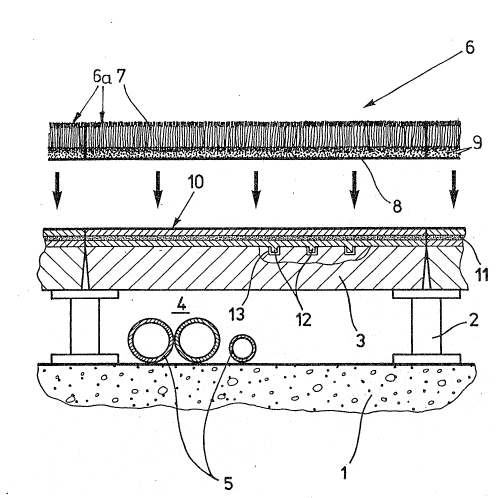
The double floor depicted in the drawing consists of an underfloor
structure 1, for example in the form of a concrete ceiling or the like,
supports 2 mounted thereon and double floor sheet members 3 or boards rest-
ing thereon. The supports 2 mean that there is a cavity 4 between the
underfloor structure 1 and the double floor sheet members 3 in order to
accommodate installed means such as are indicated in the form of pipes 5.
The double floor sheet members 3 may for instance be of chipboard, sheet
metal, stone slabs, aerated concrete slabs or the like. In the depicted
example chipboard is to be employed.
On the pre-existing double floor a covering 6 is laid which in the
drawing may be seen to be arranged at a distance therefrom. This covering
consists in the illustrated working embodiment of a plurality of tiles 6a,
which are to be laid adjacent to each other and whose edges are aligned
with the ed~es of the double floor sheet members 3 and which are so laid
that edges in alignment with one another are produced. It is therefore
possible in a simple manner to ensure that individual double floor sheet
members 3 may be uncovered and removed in order to gain access to the cavi-
ty 5. It would however also be possible to lay the tiles 6a with an offset
between their joints and the joints between double floor sheet members 3 in
order to span any small inaccuracies in the thickness oF the double floor
sheet members 3.
'
~, .
3 3 7
The covering 6 is here in the form of a fitted carpet covering.
Accordingly the tiles 6a are in the form of fitted carpet tiles or panels.
A fitted carpet of this type comprises a pile-like, textile upper layer 7
and a support layer 8 which secures the textile material in place and con-
sists of a suitable material such as synthetic resin or the like.
In order to produce magnetic atkraction between the covering 6 and
the associated base, here in the form of the double floor sheet members 3,
and consequently to ensùre reliable adhesion despite easy removal, the
covering with the associated base are furnished with means mutually mag-
netically attracting one another. These means are constituted by magneti-
cally attracting or, respectively, magnetically attractable par-ticulate
material. In the illustrated working embodiment of the invention ferromag-
netic iron powder 9 is incorporated in the support layer 8 of the covering
6. This powder is, as shown in the figure, integrated in the support layer
8 with an even distribution in space. The double floor sheet members 3
constituting the base, which in the present case are to be in the form of
chipboard, are in the illustrated working embodiment furnished with an
attachment sheet 10, in which barium ferrite powder 11 is integrated, which
after the putting in place in the layer sheet 10 may be permanently magne-
tized by the action of a magnetic field so that the ferromagnetic ironpowder 9 of the covering 6 is attracted by it. However instead of barium
ferrite it is possible furthermore to employ strontium ferrite or the like.
The layer sheet 10 consists, in the illustrated working embodiment, of a
twin layer foil, between whose upper and lower layers a particulate materi-
al, in the present case in the form of the barium ferrite powder, is ar-
ranged and by means of an adhesive or a binding material is secured in
place. However in lieu of a foil it would furthermore be possible to em-
ploy a non-woven material or a fabric or the like. In the case of a foil
it is possible for the attachment sheet to be rendered electrically con-
ducting in a simple manner, that is to say by being furnished with an elec-
trically conducting coating on all sides and/or provided with perforations
distributed over its surface and able to be filled with conducting materi-
al.
The attachment sheet 10 which here as well has a tile-like form in a
3~ size corresponding to the floor sheek members 3 or, respectively, the tiles
6a on the covering side, may be loosely arranged on the associated base,
which here is in the form of the double floor sheet member$ 3, something
which means that the same may be readily removed again. The comparakively
high area weight, resulting from the integrated metal powder, serves to
ensure a reliable anchoring effect so that the sheeting keeps in place. In
2 ~ 3 ~
order to ensure that the parts are particularly firmly kept in place, it
would naturally be possible for the attachment s~eet 10 to be furthermore
bonded to and/or interlocked with the associated base, ~or exarnple by de-
tente knobs 12 thereon, which would fit into detente holes 13 in the floor.
In the installed condition there is practically no wear or only a very
small degree of wear of the attachment sheet so underneath the covering 6,
whereas the covering is subject to wear on its upper surface and conse-
quently has to be replaced from time to time. Accordinyly in the present
case the cheaper -iron powder 9 is used in the covering 6 and the more ex-
1û pensive barium ferrite powder is employed in the base, in the present casein the attachment sheet 10 on the base side. A reverse arrangement would
naturally be possible. The incorporation of magneticallY attracting mate-
rial such as barium ferrite powder, which after incorporation can be perma-
nently magnetized, in the covering will more particularly come into qwes-
tion if the associated base consists of ferromagnetic material, as forexample will be the case with steel sheeting or, respectively, sheeting
covered with steel sheet. The same will apply for base, in whose outer
layer particulate material can be incorporated, this applying for instance
for concrete slabs and the like. In such cases there is naturally no at-
tachment sheet of the type illustrated here.
However instead of using an attachment sheet or integrating magneti-
cally attracting or magnetically attractable particulate material in the
base the same may simply be furnished with a precoat and/or a surfacing
material, there being therein a material which is suitable for causing
magnetic attraction. In order to facilitate the stirring or mixing of the
precoat or, respectively, of the surfacing material, in this case ferromag-
netic iron powder is employed for this purpose. In the covering barium
ferrite powder is accordingly to be utilized. The precoat and the surfac-
ing material may be provided jointly. In many cases however the precoat
alone can be sufficient. As a binding material it is in this respect con-
venient to employ an epoxy resin which cures quickly and gives a hard,
wear-resistant surface, something that is more particularly an advantage,
if the surface is exposed for long periods of time as is Frequently the
case on construction sites. The iron powder is preferably only stirred
into the binding material, like the epoxy resin, on site.
In those cases in which corrosion of the iron powder or the like is
likely to occur, the powder may be furnished with a suitab1e protective
layer. For this purpose zinc stearate may be used. This material is mixed
in a powder form into the iron powder or the like at a rate of approximate-
ly 2 %. Following this all the material is heated up to approxima1:ely 70
,
- : , . .
.: ' " , ". ,
,,, - .. ' ' ', ' ' .'. .. ,; ,, ,' ~ "' ,' ' ' .: '
- .- .: .. ., .. . .. ~ . :. . :: ... .
.. -.: :.. : ,- : ., . , ,. : . . . : . . . . - .:
3 ~ ~
C so that the zinc stearate fuses and forms the desired protective layer.
A preferred field of application for the coverings of the type in
accordance with the invention is exhibition stands or booths, gymnasia or
the like or removable coverings for floors underneath which cables etc,
have been laid. However t~le advantages provided by the invention make
themselves felt in connection with stair carpets and stair mats owing to
the good sllp-free attachment to the base.
.. . .~ . :
- - - . . .. :
.. ,'' . ' . : -- ' ~ : ' '
:: . :, ' . .
. .
.
,: ' -:
,: