Note: Descriptions are shown in the official language in which they were submitted.
210~
METHOD AND APPARATUS FOR
LASER-DISCHARGE IMAGING
BACKGROUND OF THE INVENTION
A. Field of the Invention
The present invention relates to digital printing
apparatus and methods, and more particularly to a system for
imaging lithographic printing plates on- or off-press using
digitally controlled laser output.
B. Description of the Related Art
Traditional techniques of introducing a printed image
onto a recording material include letterpress printing, gravure
printing and offset lithography. All of these printing methods
require a plate, usually loaded onto a plate cylinder of a
rotary press for efficiency, to transfer ink in the pattern of
the image. In letterpress printing, the image pattern is
represented on the plate in the form of raised areas that
accept ink and transfer it onto the recording medium by
impression. Gravure printing cylinders, in contrast, contain
series of wells or indentations that accept ink for deposit
onto the recording medium; excess ink must be removed from the
cylinder by a doctor blade or similar device prior to contact
between the cylinder and the recording medium.
In the case of offset lithography, the image is present
on a plate or mat as a pattern of ink-accepting (oleophilic)
and ink-repellent (oleophobic) surface areas. In a dry
printing system, the plate is simply inked and the image
transferred onto a recording material; the plate first makes
contact with a compliant intermediate surface called a blanket
cylinder which, in turn, applies the image to th~ paper or
other recording medium. In typical sheet-fed press systems,
the recording medium is pinned to an impression cylinder,
which brings it into contact with the blanket cylinder.
In a wet lithographic system, the non-image areas
are hydrophilic, and the necessary ink-repellency is provided
by an initial application of a dampening (or "fountain")
solution to the plate prior to inking. The ink-abhesive
fountain solution prevents ink from adhering to the non-image
areas, but does not affect the oleophilic character of the
image areas.
If a press is to print in more than one color, a
separate printing plate corresponding to each color is
required, each such plate usually being made photographically
as described below. In addition to preparing the appropriate
plates for the different colors, the operator must mount the
plates properly on the plate cylinders of the press, and
coordinate the positions of the cylinders so that the color
components printed by the different cylinders will be in
register on the printed copies. Each set of cylinders
associated with a particular color on a press is usually
referred to as a printing station.
In most conventional presses, the printing stations
are arranged in a straight or "in-line" configuration. Each
such station typically includes an impression cylinder, a
blanket cylinder, a plate cylinder and the necessary ink (and,
in wet systems, dampening) assemblies. The recording material
is transferred among the print stations sequentially, each
station applying a different ink color to the material to
64421-538
A. ~
e~
produce a composite multi-color image. Another configuration,
described in U.S. Patent No. 4,936,211, co-owned with the
present application, relies on a central impression cylinder
that carries a sheet of recording material past each print
station, eliminating the need for mechanical transfer of the
medium to each print station.
With either type of press, the recording medium can
be supplied to the print stations in the form of cut sheets or
a continuous "web" of material. The number of print stations
on
- 2a -
64421-538
3 2100~13
a press depends on the type of document to be printed. For
mass copying of text or simple monochrome line-art, a single
print station may suffice. To achieve full tonal rendition of
more complex monochrome images, it is customary to employ a
"duotone" approach, in which two stations apply different
densities of the same color or shade. Full-color presses apply
ink according to a selected color model, the most common being
based on cyan, magenta, yellow and black (the "CMYK~' model).
Accordingly, the CMYK model requires a minimum of four print
stations; more may be required if a particular color is to be
emphasized. The press may contain another station to apply
spot lacquer to various portions of the printed document, and
may also feature one or more "perfecting" assemblies that
invert the recording medium to obtain two-sided printing.
The plates for an offset press are usually produced
photographically. To prepare a wet plate using a typical
negative-working subtractive process, the original document is
photographed to produce a photographic negative. This negative
is placed on an aluminum plate having a water-receptive oxide
surface coated with a photopolymer. Upon exposure to light or
other radiation through the negative, the areas of the coating
that received radiation (corresponding to the dark or printed
areas of the original) cure to a durable oleophilic state. The
plate is then subjected to a developing process that removes
the uncured areas of the coating (i.e., those which did not
receive radiation, corresponding to the non-image or background
areas of the original), exposing the hydrophilic surface of the
aluminum plate.
A similar photographic process is used to create dry
plates, which typically include an ink-abhesive (e.g.,
silicone) surface layer coated onto a photosensitive layer,
which is itself coated onto a substrate of suitable stability
(e.g., an aluminum sheet). Upon exposure to actinic radiation,
the photosensitive layer cures to a state that destroys its
bonding to the surface layer. After exposure, a treatment is
applied to deactivate the photoresponse of the photosensitive
layer in unexposed areas and to further improve anchorage of
the surface layer to these areas. Immersion of the exposed
plate in developer results in dissolution and removal of the
surface layer at those portions of the plate surface that have
received radiation, thereby exposing the ink-receptive, cured
photosensitive layer.
Photographic platemaking processes tend to be time-
consuming and require facilities and equipment adequate to
support the necessary chemistry. To circumvent these
shortcomings, practitioners have developed a number of
electronic alternatives to plate imaging, some of which can be
utilized on-press. With these systems, digitally controlled
devices alter the ink-receptivity of blank plates in a pattern
representative of the image to be printed. Such imaging
devices include sources of electromagnetic-radiation pulses,
produced by one or more laser or non-laser sources, that
create chemical changes on plate blanks (thereby eliminating
the need for a photographic negative); ink-jet equipment that
directly deposits ink-repellent or ink-accepting spots on
plate blanks; and spark-discharge equipment, in which an
electrode in contact with or spaced close to a plate blank
produces electrical sparks to physically alter the topology of
the plate blank, thereby producing "dots" which collectively
form a desired image (see, e.q., U.S. Patent No. 4,911,075,
co-owned with the present application).
Because of the ready availability of laser equipment
and their amenability to digital control, significant effort
64421-538
has been devoted to the development of laser-based imaging
systems. Early examples utilized lasers to etch away material
from a plate blank to form an intaglio or letterpress pattern.
See, e.q., U.S. Patent Nos. 3,506,779; 4,347,785. This
approach was later extended to production of lithographic
plates, e.g., by removal of a hydrophilic surface to reveal an
oleophilic underlayer. See, e.q., U.S. Patent No. 4,054,094.
//
64421-538
.. .....
_5_ 21~0 i~3
systems generally require high-power lasers, which are
expensive and slow.
A second approach to laser imaging involves the use of
thermal-transfer materials. See, e.q., U.S. Patent Nos.
3,945,318; 3,962,513; 3,964,389; and 4,395,946. With these
systems, a polymer sheet transparent to the radiation emitted
by the laser is coated with a transferable material. During
operation the transfer side of this construction is brought
into contact with an acceptor sheet, and the transfer material
is selectively irradiated through the transparent layer.
Irradiation causes the transfer material to adhere
preferentially to the acceptor sheet. The transfer and
acceptor materials exhibit different affinities for fountain
solution and/or ink, so that removal of the transparent layer
together with unirradiated transfer material leaves a suitably
imaged, finished plate. Typically, the transfer material is
oleophilic and the acceptor material hydrophilic. Plates
produced with transfer-type systems tend to exhibit short
useful lifetimes due to the limited amount of material that can
effectively be transferred. In addition, because the transfer
process involves melting and resolidification of material,
image quality tends to be visibly poorer than that obtainable
with other methods.
Finally, lasers can be used to expose a photosensitive
blank for traditional chemical processing. See, e.q., U.S.
Patent Nos. 3,506,779; 4,020,762. In an alternative to this
approach, a laser has been employed to selectively remove, in
an imagewise pattern, an opaque coating that overlies a
photosensitive plate blank. The plate is then exposed to a
source of radiation, with the unremoved material acting as a
mask that prevents radiation from reaching underlying portions
of the plate. See, e.g., U.S. Patent No. 4,132,168. Either of
these imaging techniques requires the cumbersome chemical
processing associated with traditional, non-digital
platemaking.
' -6- 2100413
DESCRIPTION OF THE INVENTION
A. Brief Summary of the Invention
The present invention enables rapid, efficient production
of lithographic printing plates using relatively inexpensive
laser equipment that operates at low to moderate power levels.
The imaging techniques described herein can be used in
conjunction with a variety of plate-blank constructions,
enabling production of "wet" plates that utilize fountain
solution during printing or "dry" plates to which ink is
applied directly. In one aspect, the invention relates to
methods of imaging the constructions hereinafter described; in
another aspect, the invention relates to apparatus for
providing laser output to the surface of constructions to be
imaged.
A key aspect of the present invention lies in use of
materials that enhance the ablative efficiency of the laser
beam. Substances that do not heat rapidly or absorb
significant amounts of radiation will not ablate unless they
are irradiated for relatively long intervals and/or receive
high-power pulses; such physical limitations are commonly
associated with lithographic-plate materials, and account for
the prevalence of high-power lasers in the prior art.
One suitable plate construction includes a first layer
and a substrate underlying the first layer, the substrate being
characterized by efficient absorption of infrared ("IR")
radiation, and the first layer and substrate having different
affinities for ink (in a dry-plate construction) or an abhesive
fluid for ink (in a wet-plate construction). Laser radiation
is absorbed by the substrate, and ablates the substrate surface
in contact with the first layer; this action disrupts the
anchorage of the substrate to the overlying first layer, which
is then easily removed at the points of exposure. The result
of removal is an image spot whose affinity for the ink or ink-
abhesive fluid differs from that of the unexposed first layer.
7~ 3
In a variation of this embodiment, the first layer,
rather than the substrate, absorbs IR radiation. In this case
the substrate serves a support function and provides
contrasting affinity characteristics.
In both of these two-ply plate types, a single layer
serves two separate functions, namely, absorption of IR
radiation and interaction with ink or ink-abhesive fluid. In
a second embodiment, these functions are performed by two
separate layers. The first, topmost layer is chosen for its
affinity for (or repulsion of) ink or an ink-abhesive fluid.
Underlying the first layer is a second layer, which absorbs IR
radiation. A strong, stable substrate underlies the second
layer, and is characterized by an affinity for (or repulsion
of) ink or an ink-abhesive fluid opposite to that of the first
layer. Exposure of the plate to a laser pulse ablates the
absorbing second layer, weakening the topmost layer as well.
As a result of ablation of the second layer, the weakened
surface layer is no longer anchored to an underlying layer,
and is easily removed. The disrupted topmost layer (and any
debris remaining from destruction of the absorptive second
layer) is removed in a post-imaging cleaning step. This, once
again, creates an image spot having a different affinity for
the ink or ink-abhesive fluid than the unexposed first layer.
Post-imaging cleaning can be accomplished using a
contact cleaning device such as a rotating brush (or other
suitable means as described in Canadian Patent No. 2,052,678
issued February 1, 1994 and commonly owned with the present
application). Although post-imaging cleaning represents an
64421-538
,
- 7 ~! ~ fJj f~ ~ ~
additional processing step, the persistence of the topmost
layer during imaging can actually prove beneficial. Ablation
of the absorbing layer creates debris that can interfere with
transmission of the laser beam (e.g., by depositing on a
focusing lens or as an aerosol (or mist) of fine particles
that partially blocks transmission). The disrupted but
unremoved topmost layer prevents escape of this debris.
64421-538
2100413
--8--
Either of the foregoing embodiments can be modified for
more efficient performance by addition, beneath the absorbing
layer, of an additional layer that reflects IR radiation. This
additional layer reflects any radiation that penetrates the
absorbing layer back through that layer, so that the effective
flux through the absorbing layer is significantly increased.
The increase in effective flux improves imaging performance,
reducing the power (that is, energy of the laser beam
multiplied by its exposure time) necessary to ablate the
absorbing layer. Of course, the reflective layer must either
be removed along with the absorbing layer by action of the
laser pulse, or instead serve as a printing surface instead of
the substrate.
The imaging apparatus of the present invention includes
at least one laser device that emits in the IR, and preferably
near-IR region; as used herein, "near-IR" means imaging
radiation whose lambda~Ax lies between 700 and 1500 nm. An
important feature of the present invention is the use of solid-
state lasers (commonly termed semiconductor lasers and
typically based on gallium aluminum arsenide compounds) as
sources; these are distinctly economical and convenient, and
may be used in conjunction with a variety of imaging devices.
The use of near-IR radiation facilitates use of a wide range of
organic and inorganic absorption compounds and, in particular,
semiconductive and conductive types.
Laser output can be provided directly to the plate
surface via lenses or other beam-guiding components, or
transmitted to the surface of a blank printing plate from a
remotely sited laser using a fiber-optic cable. A controller
and associated positioning hardware maintains the beam output
at a precise orientation with respect to the plate surface,
scans the o-,ltput over the surface, and activates the laser at
positions adjacent selected points or areas of the plate. The
controller responds to incoming image signals corresponding to
the original document or picture being copied onto the plate to
9 210~ 1~3
produce a precise negative or positive image of that original.
The image signals are stored as a bitmap data file on a
computer. Such files may be generated by a raster image
processor (RIP) or other suitable means. For example, a RIP
can accept input data in page-description language, which
defines all of the features required to be transferred onto the
printing plate, or as a combination of page-description
language and one or more image data files. The bitmaps are
constructed to define the hue of the color as well as screen
frequencies and angles.
The imaging apparatus can operate on its own, functioning
solely as a platemaker, or can be incorporated directly into a
lithographic printing press. In the latter case, printing may
commence immediately after application of the image to a blank
plate, thereby reducing press set-up time considerably. The
imaging apparatus can be configured as a flatbed recorder or as
a drum recorder, with the lithographic plate blank mounted to
the interior or exterior cylindrical surface of the drum.
Obviously, the exterior drum design is more appropriate to use
in situ, on a lithographic press, in which case the print
cylinder itself constitutes the drum component of the recorder
or plotter.
In the drum configuration, the requisite relative motion
between the laser beam and the plate is achieved by rotating
the drum (and the plate mounted thereon) about its axis and
moving the beam parallel to the rotation axis, thereby scanning
the plate circumferentially so the image "grows" in the axial
direction. Alternatively, the beam can move parallel to the
drum axis and, after each pass across the plate, increment
angularly so that the image on the plate "grows"
circumferentially. In both cases, after a complete scan by the
beam, an image corresponding (positively or n,egatively) to the
original document or picture will have been applied to the
surface of the plate.
In the flatbed configuration, the beam is drawn across
either axis of the plate, and is indexed along the other axis
~ ., ... ,. . ... ... _
- lo - ~7.. ~ 3
after each pass. Of course, the requisite relative motion
between the beam and the plate may be produced by movement of
the plate rather than (or in addition to) movement of the
beam.
Regardless of the manner in which the beam is
scanned, it is generally preferable (for reasons of speed~ to
employ a plurality of lasers and guide their outputs to a
single writing array. The writing array is then indexed,
after completion of each pass across or along the plate, a
distance determined by the number of beams emanating from the
array, and by the desired resolution (i.e, the number of image
points per unit length).
Accordingly in the first aspect, the invention
provides methods and apparatus for laser imaging of "wet"
lithographic printing plates having hydrophilic surface layers
that accept fountain solution and oleophilic substrates that
accept ink, imaging of the plate removing (or facilitating
removal of) the hydrophilic surface layer to reveal the ink-
accepting layer therebeneath, thereby forming a lithographic
image.
Thus, according to the first broad aspect, the
invention provides a method of imaging a lithographic plate,
the method comprising the steps of: a. providing a plate
having a work surface and comprising first and second layers
differing in their affinities for at least one printing liquid
selected from the group consisting of ink and an abhesive
fluid for ink, the first layer being ablatable by absorption
64421-538
.. ~ . ... .. . .
~7
- lOa -
of imaging infrared radiation, the plate further comprising
means for reflecting imaging infrared radiation into the first
layer; b. spacing at least one laser source capable of
producing an infrared output opposite the work surface of the
plate; c. guiding the output of each laser to focus on the
work surface; d. moving the laser output and work surface
relative to one another to effect a scan of the work surface
by the laser output; and e. selectively exposing, in a pattern
representing an image, the work surface to the laser output
during the course of the scan so as to remove or facilitate
the removal of at least the first layer, thereby directly
producing on the plate an array of image features.
Also according to the first aspect, the invention
provides printing apparatus comprising: support means
supporting a printing plate, the printing plate having a work
surface and comprising a topmost first layer, a second layer
underlying the first layer and ablatable by absorption of
imaging infrared radiation, and a substrate underlying the
second layer, the first layer being hydrophilic and the
substrate being oleophilic and hydrophobic; at least one laser
source capable of producing an infrared output; guiding means
for guiding the output of each laser to focus on the work
surface; means for moving the guiding means and support means
relative to one another to effect a scan of the work surface
by the laser output; and means for selectably removing, in a
pattern representing an image, at least the first layer by
exposing the printing surface to the laser output during the
64421-538
r~
- lOb -
source of the scan, thereby directly producing on the plate an
array of image features.
In a second aspect, the invention provides methods
and apparatus for laser imaging of "wet" or "dry" lithographic
printing plates designed for highly efficient use of laser
energy through reflection back into the imaging layer of laser
energy that has passed through that layer.
Thus, according to a second broad aspect, the
invention provides a method of imaging a lithographic plate,
the method comprising the steps of: a. providing a plate
having a work surface and comprising first and second layers
differing in their affinities for at least one printing liquid
selected from the group consisting of ink and an abhesive
fluid for ink, the first layer being ablatable by absorption
of imaging infrared radiation, the plate further comprising
means for reflecting imaging infrared radiation into the first
layer; b. spacing at least one laser source capable of
producing an infrared output opposite the work surface of the
plate; c. guiding the output of each laser to focus on the
work surface; d. moving the laser output and work surface
relative to one another to effect a scan of the work surface
by the laser output; and e. selectively exposing, in a pattern
representing an image, the work surface to the laser output
during the course of the scan so as to remove or facilitate
the removal of at least the first layer, thereby directly
producing on the plate an array of image features.
Also according to a second broad aspect, the
64421-538
~ .. .. . . . . ..
- lOc -
invention provides a method of imaging a lithographic plate,
the method comprising the steps of: a. providing a plate
having a work surface and comprising a topmost first layer, a
second layer underlying the first layer and ablatable by
absorption of imaging infrared radiation, and a substrate
underlying the second layer, the first layer and the substrate
exhibiting different affinities for at least one printing
liquid selected from the group consisting of ink and an
abhesive fluid for ink, the plate further comprising means for
reflecting imaging radiation into the second layer; b. spacing
at least one laser source capable of producing an infrared
output opposite the work surface of the plate; c. guiding the
output of each laser to focus on the work surface; d. moving
the laser output and work surface relative to one another to
effect a scan of the work surface by the laser output; and e.
selectively exposing, in a pattern representing an image, the
work surface to the laser output during the course of the scan
so as to remove or facilitate the removal of at the first and
second layers, thereby directly producing on the plate an
array of image features.
Also according to a second broad aspect, the
invention provides printing apparatus comprising: support
means supporting a printing plate, the printing plate having a
work surface and comprising first and second layers differing
in their affinities for at least one printing liquid selected
from the group consisting of ink and an abhesive fluid for
ink, the first layer being ablatable by absorption of imaging
64421-538
r~
.. ~, ., . . . .. . . . ~
- lOd -
infrared radiation, the plate further comprising means for
reflecting imaging infrared radiation into the first layer; at
least one laser source capable of producing an infrared
output; guiding means for guiding the output of each laser to
focus on the work surface; means for moving the guiding means
and support means relative to one another to effect a scan of
the work surface by the laser output; and means for selectably
removing, in a pattern representing an image, at least the
first layer by exposing the printing surface to the laser
output during the source of the scan, thereby directly
producing on the plate an array of image features.
Also according to the second broad aspect, the
invention provides printing apparatus comprising: support
means supporting a printing plate, the printing plate having a
work surface and comprising a topmost first layer, a second
layer underlying the first layer and ablatable by absorption
of imaging infrared radiation, and a substrate underlying the
second layer, the first layer and the substrate exhibiting
different affinities for at least one printing liquid selected
from the group consisting of ink and an abhesive fluid for
ink, the plate further comprising means for reflecting imaging
radiation into the second layer; at least one laser source
capable of producing an infrared output;
guiding means for guiding the output of each laser to focus on
the work surface; means for moving the guiding means and
support means relative to one another to effect a scan of the
work surface by the laser output; and means for selectably
64421-538
,, , . , , . . . . ~ ... .. . . .
- lOe -
removing, in a pattern representing an image, at least the
first layer by exposing the printing surface to the laser
output during the source of the scan, thereby directly
producing on the plate an array of image features.
In a third aspect, the invention provides methods
and apparatus for laser imaging of "wet" or "dry" lithographic
printing plates in a manner that does not require use of a
cleaning solvent.
Thus, according to the third aspect, the invention
provides a method of imaging a lithographic plate, the method
comprising the steps of: a. providing a plate having a work
surface and comprising a topmost first layer, a second layer
underlying the first layer and ablatable by absorption of
imaging infrared radiation, and a substrate underlying the
second layer, the first layer and the substrate exhibiting
different affinities for at least one printing liquid selected
from the group consisting of ink and an abhesive fluid for
ink; b. spacing at least one laser source capable of producing
an infrared output opposite the work surface of the plate; c.
guiding the output of each laser to focus on the work surface;
d. moving the laser output and work surface relative to one
another to effect a scan of the work surface by the laser
output; and e. selectively exposing, in a pattern representing
an image, the work surface to the laser output during the
course of the scan; f. mechanically removing, without a
cleaning solvent, remaining portions of the first layer where
the second layer has been ablated so as to directly produce on
64421-538
g~, ~,
~, ,,,~
- lof ~ ~ 7 Y,
the plate an array of image features.
Also according to the third aspect, the invention
provides printing apparatus comprising: support means
supporting a printing plate, the printing plate having a work
surface and comprising a topmost first layer, a second layer
underlying the first layer and ablatable by absorption of
imaging infrared radiation, and a substrate underlying the
second layer, the first layer and the substrate exhibiting
different affinities for at least one printing liquid selected
from the group consisting of ink and an abhesive fluid for
ink; at least one laser source capable of producing an
infrared output; guiding means for guiding the output of each
laser to focus on the work surface; means for moving the
guiding means and support means relative to one another to
effect a scan of the work surface by the laser output; means
for selectively exposing, in a pattern representing an image,
the work surface to the laser output during the course of the
scan; and means for mechanically removing, without a cleaning
solvent, remaining portions of the first layer where the
second layer has been ablated so as to directly produce on the
plate an array of image features.
B. Brief DescriPtion of the Drawinqs
The foregoing discussion will be understood more
readlly from the following detailed description of the
invention, when taken in conjuction with accompanying
drawings, in which:
64421-538
~' .
7.~ 3
- lOg -
FIG. 1 is an isometric view of the cylindrical embodiment
of an imaging apparatus in accordance with the present
invention, and which operates in conjuction with a diagonal-
array wrltlng array;
FIG. 2 is a schematic depiction of the embodiment shown
in FIG. 1, and which illustrates in greater detail its
mechanism of operation;
FIG 3. is a front-end view of a writing array for imaging
in accordance with the present invention, and in which imaging
elements are arranged in a diagonal array;
FIG. 4 is an isometric view of the cylindrical embodiment
of an imaging apparatus in accordance with the present
invention, and which operates in conjuction with a linear-
array writing array;
64421-538
G
.. .. .
- -11- 2~ 13
FIG. 5 is an isometric view of the front of a writing
array for imaging in accordance with the present
invention, and in which imaging elements are arranged in a
linear array;
FIG. 6 is a side view of the writing array depicted in
FIG. 5;
FIG. 7 is an isometric view of the flatbed embodiment of
an imaging apparatus having a linear lens array;
FIG. 8 is an isometric view of the interior-drum
embodiment of an imaging apparatus having a linear lens
array;
FIG. 9 is a cutaway view of a remote laser and beam-
guiding system;
FIG. 10 is an enlarged, partial cutaway view of a lens
element for focusing a laser beam from an optical fiber
onto the surface of a printing plate;
FIG. 11 is an enlarged, cutaway view of a lens element
having an integral laser;
FIG. 12 is a schematic circuit diagram of a laser-driver
circuit suitable for use with the present invention;
FIGS. 13A-13H are en~arged sectional views showing
lithographic plates imageable in accordance with the
present invention;
FIG. 14A is an isometric view of a typical laser diode;
FIG. 14B is a plan view of the diode shown in FIG. 14A,
showing the dispersion of radiation exiting therefrom
~-' 2100413
-12-
along one dimension;
FIG. 14C is an elevation of the diode shown in FIG. 14A,
showing the dispersion of radiation exiting therefrom
along the other dimension;
FIG. 15 illustrates a divergence-reduction lens for use in
conjunction with the laser diode shown in FIGS. 14A-14C;
and
FIG. 16 schematically depicts a focusing arrangement that
provides an alternative to the apparatus shown in FIG. 9.
C. Detailed Description of the Preferred Embodiments
1. Imaging Apparatus
a. Exterior-Drum Recordinq
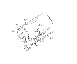
Refer first to FIG. 1 of the drawings, which illustrates
the exterior drum embodiment of our imaging system. The
assembly includes a cylinder 50 around which is wrapped a
lithographic plate blank 55. Cylinder 50 includes a void
segment 60, within which the outside margins of plate 55 are
secured by conventional clamping means (not shown). We note
that the size of the void segment can vary greatly depending on
the environment in which cylinder 50 is employed.
If desired, cylinder 50 is straightforwardly incorporated
into the design of a conventional lithographic press, and
serves as the plate cylinder of the press. In a typical press
construction, plate 55 receives ink from an ink train, whose
terminal cylinder is in rolling engagement with cylinder 50.
The latter cylinder also rotates in contact with a blanket
cylinder, which transfers ink to the recording medium. The
press may have more than one such printing assembly arranged in
d ~:
a linear array. Alternatively, a plurality of assemblies may
be arranged about a large central impression cylinder in
rolling engagement with all of the blanket cylinders.
The recording medium is mounted to the surface of
the impression cylinder, and passes through the nip between
that cylinder and each of the blanket cylinders. Suitable
central-impression and in-line press configurations are
described in Canadian Patent No. 2,099,560 issued January 30,
1996 (commonly owned with the present application) and the
'075 patent.
Cylinder 50 is supported in a frame and rotated by a
standard electric motor or other conventional means
(illustrated schematically in FIG. 2). The angular position
of cylinder 50 is monitored by a shaft encoder (see FIG. 4).
A writing array 65, mounted for movement on a lead screw 67
and a guide bar 69, traverses plate 55 as it rotates. Axial
movement of writing array 65 results from rotation of a
stepper motor 72, which turns lead screw 67 and thereby shifts
the axial position of writing array 55. Stepper motor 72 is
activated during the time writing array 65 is positioned over
void 60, after writing array 65 has passed over the entire
surface of plate 55. The rotation of stepper motor 72 shifts
writing array 65 to the appropriate axial location to begin
the next imaging pass.
The axial index distance between successive imaging
passes is determined by the number of imaging elements in
writing array 65 and their configuration therein, as well as
by the desired resolution. As shown in FIG. 2, a series of
64421-538
17 q ~
laser sources L1, L2, L3 ... Ln, driven by suitable laser
drivers collectively designated by reference numeral 75 (and
discussed in greater detail below), each provide output to a
fiber-optic cable. The lasers are preferably gallium-arsenide
models, although any high-speed lasers that emit in the near
infrared region can be utilized advantageously.
The size of an image feature (i.e., a dot, spot or
area) and image resolution can be varied in a number of ways.
The
/
/
/
/
- 13a -
64421-538
~.
-14- 2100 ~13
laser pulse must be of sufficient power and duration to produce
useful ablation for imaging; however, there exists an upper
limit in power levels and exposure times above which further
useful, increased ablation is not achieved. Unlike the lower
threshold, this upper limit depends strongly on the type of
plate to be imaged.
Variation within the range defined by the minimum and
upper parameter values can be used to control and select the
size of image features. In addition, so long as power levels
and exposure times exceed the minimum, feature size can be
changed simply by altering the focusing apparatus (as discussed
below). The final resolution or print density obtainable with
a given-sized feature can be enhanced by overlapping image
features (e.g., by advancing the writing array an axial
distance smaller than the diameter of an image feature).
Image-feature overlap expands the number of gray scales
achievable with a particular feature.
The final plates should be capable of delivering at least
1,000, and preferably at least 50,000 printing impressions.
This requires fabrication from durable material, and imposes
certain minimum power requirements on the laser sources. For a
laser to be capable of imaging the plates described below, its
power output should be at least 0.2 megawatt/in2 and preferably
at least 0.6 megawatt/in2. Significant ablation ordinarily
does not occur below these power levels, even if the laser beam
is applied for an extended time.
Because feature sizes are ordinarily quite small -- on
the order of 0.5 to 2.0 mils -- the necessary power intensities
are readily achieved even with lasers having moderate output
levels (on the order of about 1 watt); a focusing apparatus, as
discussed below, concentrates the entire laser output onto the
small feature, resulting in high effective energy densities.
The cables that carry laser output are collected into a
bundle 77 and emerge separately into writing array 65. It may
prove desirable, in order to conserve power, to maintain the
i,~ ", ~
bundle in a configuration that does not require bending above
the fiber's critical angle of refraction (thereby maintaining
total internal reflection); however, we have not found this
necessary for good performance.
Also as shown in FIG. 2, a controller 80 actuates
laser drivers 75 when the associated lasers reach appropriate
points opposite plate 55, and in addition operates stepper
motor 72 and the cylinder drive motor 82. Laser drivers 75
should be capable of operating at high speed to facilitate
imaging at commercially practical rates. The drivers
preferably include a pulse circuit capable of generating at
least 40,000 laser-driving pulses/second, with each pulse
being relatively short, i.e., on the order of 10-15 ~sec
(although pulses of both shorter and longer durations have
been used with success). A suitable design is described
below.
Controller 80 receives data from two sources. The
angular position of cylinder 50 with respect to writing array
65 is constantly monitored by a detector 85 (described in
greater detail below), which provides signals indicative of
that position to controller 80. In addition, an image data
source (e.g., a computer) also provides data signals to
controller 80. The image data define points on plate 55 where
image spots are to be written. Controller 80, therefore,
correlates the instantaneous relative positions of writing
array 65 and plate 55 (as reported by detector 85) with the
image data to actuate the appropriate laser drivers at the
appropriate times during scan of plate 55. The control
- 15 -
64421-538
circuitry required to implement this scheme is well-known in
the scanner and plotter art; a suitable design is described in
co-pending Canadian patent application Serial No. 2,099,561
filed July 2, 1993 and commonly owned with the present
application.
The laser output cables terminate in lens
assemblies, mounted within writing array 65, that precisely
focus the beams onto the surface of plate 55. A suitable
lens-assembly design is described below; for purposes of the
iQ ~es-~ iircu~ri~n ,
- 15a -
64421-538
.. .. .
-16- 2100~13
these assemblies are generically indicated by reference numeral
96. The manner in which the lens assemblies are distributed
within writing array 65, as well as the design of the writing
array, require careful design considerations. One suitable
configuration is illustrated in FIG. 3. In this arrangement,
lens assemblies 96 are staggered across the face of body 65.
The design preferably includes an air manifold 130, connected
to a source of pressurized air and containing a series of
outlet ports aligned with lens assemblies 96. Introduction of
air into the manifold and its discharge through the outlet
ports cleans the lenses of debris during operation, and also
purges fine-particle aerosols and mists from the region between
lens assemblies 96 and plate surface 55.
The staggered lens design facilitates use of a greater
number of lens assemblies in a single head than would be
possible with a linear arrangement. And since imaging time
depends directly on the number of lens elements, a staggered
design offers the possibility of faster overall imaging.
Another advantage of this configuration stems from the fact
that the diameter of the beam emerging from each lens assembly
is ordinarily much smaller than that of the focusing lens
itself. Therefore, a linear array requires a relatively
significant minimum distance between beams, and that distance
may well exceed the desired printing density. This results in
the need for a fine stepping pitch. By staggering the lens
assemblies, we obtain ti~hter spacing between the laser beams
and, assuming the spacing is equivalent to the desired print
density, can therefore index across the entire axial width of
the array. Controller 80 either receives image data already
arranged into vertical columns, each corresponding to a
different lens assembly, or can progressively sample, in
columnar fashion, the contents of a memory buffer containing a
complete bitmap representation of the image to be transferred.
In either case, controller 80 recognizes the different relative
positions of the lens assemblies with respect to plate 55 and
, . .
-17_ 2100~13
actuates the appropriate laser only when its associated lens
assembly is positioned over a point to be imaged.
An alternative array design is illustrated in FIG. 4,
which also shows the detector 85 mounted to the cylinder 50.
Preferred detector designs are described in the '199
application. In this case the writing array, designated by
reference numeral 150, comprises a long linear body fed by
fiber-optic cables drawn from bundle 77. The interior of
writing array 150, or some portion thereof, contains threads
that engage lead screw 67, rotation of which advances writing
array 150 along plate 55 as discussed previously. Individual
lens assemblies 96 are evenly spaced a distance B from one
another. Distance B corresponds to the difference between the
axial length of plate 55 and the distance between the first and
last lens assembly; it represents the total axial distance
traversed by writing array 150 during the course of a complete
scan. Each time writing array 150 encounters void 60, stepper
motor 72 rotates to advance writing array 150 an axial distance
equal to the desired distance between imaging passes (i.e., the
print density). This distance is smaller by a factor of n than
the distance indexed by the previously described embodiment
(writing array 65), where n is the number of lens assemblies
included in writing array 65.
Writing array 150 includes an internal air manifold 155
and a series of outlet ports 160 aligned with lens assemblies
96. Once again, these function to remove debris from the lens
assemblies and imaging region during operation.
b. Flatbea Recordinq
The imaging apparatus can also take the form of a flatbed
recorder, as depicted in FIG. 7. In the illustrated
embodiment, the flatbed apparatus includes a stationary support
175, to which the outer margins of plate 55 are mounted by
conventional clamps or the like. A writing array 180 receives
.. ... ........ .
18 21~13
fiber-optic cables from bundle 77, and includes a series of
lens assemblies as described above. These are oriented toward
plate 55.
A first stepper motor 182 advances writing array 180
across plate 55 by means of a lead screw 184, but now writing
array 180 is stabilized by a bracket 186 instead of a guide
bar. Bracket 180 is indexed along the opposite axis of support
175 by a second stepper motor 188 after each traverse of plate
55 by writing array 180 (along lead screw 184). The index
distance is equal to the width of the image swath produced by
imagewise activation of the lasers during the pass of writing
array 180 across plate 55. After bracket 186 has been indexed,
stepper motor 182 reverses direction and imaging proceeds back
across plate 55 to produce a new image swath just ahead of the
previous swath.
It should be noted that relative movement between writing
array 180 and plate 155 does not require movement of writing
array 180 in two directions. Instead, if desired, support 175
can be moved along either or both directions. It is also
possible to move support 175 and writing array 180
simultaneously in one or both directions. Furthermore,
although the illustrated writing array 180 includes a linear
arrangement of lens assemblies, a staggered design is also
feasible.
c. Interior-Arc Recordinq
Instead of a flatbed, the plate blank can be supported on
an arcuate surface as il~ustrated in FIG. 8. This
configuration permits rotative, rather than linear movement of
the writing array and/or the plate.
The interior-arc scanning assembly includes an ~rcuate
plate support 200, to which a blank plate 55 is clamped or
otherwise mounted. An L-shaped writing array 205 includes a
bottom portion, which accepts a support bar 207, and a front
-19- 21~0~1~
portion containing channels to admit the lens assemblies. In
the preferred embodiment, writing array 205 and support bar 207
remain fixed with respect to one another, and writing array 205
is advanced axially across plate 55 by linear movement of a
rack 210 mounted to the end of support bar 207. Rack 210 is
moved by rotation of a stepper motor 212, which is coupled to a
gear 214 that engages the teeth of rack 210. After each axial
traverse, writing array 205 is indexed circumferentially by
rotation of a gear 220 through which support bar 207 passes and
to which it is fixedly engaged. Rotation is imparted by a
stepper motor 222, which engages the teeth of gear 220 by means
of a second gear 224. Stepper motor 222 remains in fixed
alignment with rack 210.
After writing array 205 has been indexed
circumferentially, stepper motor 212 reverses direction and
imaging proceeds back across plate 55 to produce a new image
swath just ahead of the previous swath.
d. Output Guide and Lens Assembly
Suitable means for guiding laser output to the surface of
a plate blank are illustrated in FIGS. 9-11. Refer first to
FIG. 9, which shows a remote laser assembly that utilizes a
fiber-optic cable to transmit laser pulses to the plate. In
this arrangement a laser source 250 receives power via an
electrical cable 252. Laser 250 is seated within the rear
segment of a housing 255. Mounted within the forepart of
housing are two or more focusing lenses 260a, 260b, which focus
radiation emanating from'laser 250 onto the end face of a
fiber-optic cable 265, which is preferably (although not
necessarily) secured within housing 255 by a removable
retaining cap 267. Cable 265 conducts the output of laser 250
to an output assembly 270, which is illustrated in greater
detail in FIG. 10.
The illustrative double-lens system shown in FIG. 9,
while adequate in many arrangements, can be improved to
. .
~ -20~ 1 3
accommodate the characteristics of typical laser diodes. FIG.
14A shows a common type of laser diode, in which radiation is
emitted through a slit 502 in the diode face 504. The
dimensions of slit 502 are specified along two axes, a long
axis 5021 and a short axis 502s. Radiation disperses as it
exits slit 502, diverging at the slit edges. This is shown in
FIGS. 14B and 14C. The dispersion around the short edges
(i.e.~ along long axis 5021), as depicted in FIG. 14B (where
diode 500 is viewed in plan), is defined by an angle ~; the
dispersion around the long edges (i.e., along short axis 502s),
as depicted in FIG. 14C (where diode 500 is viewed in
elevation), is defined by an angle ~. The numerical aperture
(NA) of slit 502 along either axis is defined as one-half the
sine of the dispersion angle.
For optimum performance, a = ~ and the unitary NA is less
than 0.3, and preferably less than 0.2. Small NA values
correspond to large depths-of-focus, and therefore provide
working tolerances that facilitate convenient focus of the
radiation onto the end face of a fiber-optic cable. Without
correction, however, these desirable conditions are usually
impossible; laser diode 500 typically does not radiate at a
constant angle, with divergence around the short edges
exceeding that around the long edges, so ~ > ~.
Assuming that the NA along long axis 5021 falls within
acceptable limits, the NA along the short axis 502s can be made
to approach the long-axis NA by controlling dispersion around
the long edges. This is achieved using a divergence-reduction
lens. Suitable configurations for such a lens include a
cylinder, a planoconvex b'ar, and the concave-convex trough
shown in FIG. 15. The divergence-reduction lens is positioned
adjacent slit 502 with its length following long axis 5021, and
with its convex face adjacent the slit.
If the NA along long axis 5021 also exceeds acceptable
limits, the dispersion around the short edges can be diminished
using a suitable condensing lens. In this case the optical
21~û~13
-21-
characteristics of divergence-reduction lens 520 are chosen
such that the NA along short axis 502s approaches that along
long axis 5021 after correction.
Advantageous use of a divergence-reduction lens is not
limited to slit-type emission apertures. Such lenses can be
usefully applied to any asymmetrical emission aperture in order
to ensure even dispersion around its perimeter.
With the radiation emitted through slit 502 fully
corrected as described above, it can be straightforwardly
focused onto the end face of a fiber-optic cable by a suitable
optical arrangement, such as that illustrated in FIG. 16. The
depicted optical arrangement includes a divergence-reduction
lens 520, oriented with respect to diode 500 as described
above; a collimating lens 525, which draws the corrected but
still divergent radiation into parallel rays; and a focusing
lens 530, which focuses the parallel rays onto the end face
265f of fiber-optic cable 265. In some cases it is possible to
replace lenses 525 and 530 with a single, double-convex lens
535 as shown.
It may also prove necessary or desirable to utilize a
fiber with a face 265f that is smaller in diameter than the
length of diode's large axis. Unless the the radiation emitted
along the long axis is concentrated optically, the loss of
radiation that fails to impinge on end face 265f must either be
accepted or the end face distorted (e.g., into an ellipse) to
more closely match the dimensions of slit 502.
Refer now to FIG. 10, which illustrates an illustrative
output assembly to guide radiation from fiber-optic cable 265
to the imaging surface. As shown in the figure, fiber-optic
cable 265 enters the assembly 270 through a retaining cap 274
(which is preferably removable). Retaining cap 274 fits over a
generally tubular body 276, which contains a series of threads
278. Mounted within the forepart of body 276 are two or more
focusing lenses 280a, 280b. Cable 265 is carried partway
through body 276 by a sleeve 280. Body 276 defines a hollow
-22- 2100413
channel between inner lens 280b and the terminus of sleeve 280,
so the end face of cable 265 lies a selected distance A from
inner lens 280b. The distance A and the focal lengths of
lenses 280a, 280b are chosen so the at normal working distance
from plate 55, the beam emanating from cable 265 will be
precisely focused on the plate surface. This distance can be
altered to vary the size of an image feature.
Body 276 can be secured to writing array 65 in any
suitable manner. In the illustrated embodiment, a nut 282
engages threads 278 and secures an outer flange 284 of body 276
against the outer face of writing array 65. The flange may,
optionally, contain a transparent window 290 to protect the
lenses from possible damage.
Alternatively, the lens assembly may be mounted within
the writing array on a pivot that permits rotation in the axial
direction (i.e., with reference to FIG. 10, through the plane
of the paper) to facilitate fine axial positioning adjustment.
We have found that if the angle of rotation is kept to 4~ or
less, the circumferential error produced by the rotation can be
corrected electronically by shifting the image data before it
is transmitted to controller 80.
Refer now to FIG. 11, which illustrates an alternative
design in which the laser source irradiates the plate surface
directly, without transmission through fiber-optic cabling. As
shown in the figure, laser source 250 is seated within the rear
segment of an open housing 300. Mounted within the forepart of
housing 300 are two or more focusing lenses 302a, 302b, which
focus radiation emanating from laser 250 onto the surface of
plate 55. The housing ma'y, optionally, include a transparent
window 305 mounted flush with the open end, and a heat sink
307.
It should be understood that while the preceding
discussion of imaging configurations and the accompanying
figures have assumed the use of optical fibers, in each case
the fibers can be eliminated through use of the embodiment
shown in FIG. 11.
.. . . . ......
-23- 2 1 0 0 4 1 3
e. Driver Circuitry
A suitable circuit for driving a diode-type (e.g.,
gallium arsenide) laser is illustrated schematically in FIG.
12. Operation of the circuit is governed by controller 80,
which generates a fixed-pulse-width signal (preferably 5 to 20
ysec in duration) to a high-speed, high-current MOSFET driver
325. The output terminal of driver 325 is connected to the
gate of a MOSFET 327. Because driver 325 is capable of
supplying a high output current to quickly charge the MOSFET
gate capacitance, the turn-on and turn-off times for MOSFET 327
are very short (preferably within 0.5 ~sec) in spite of the
capacitive load. The source terminal of MOSFET 327 is
connected to ground potential.
When MOSFET 327 is placed in a conducting state, current
flows through and thereby activates a laser diode 330. A
variable current-limiting resistor 332 is interposed between
MOSFET 327 and laser diode 330 to allow adjustment of diode
output. Such adjustment is useful, for example, to correct for
different diode efficiencies and produce identical outputs in
all lasers in the system, or to vary laser output as a means of
controlling image size.
A capacitor 334 is placed across the terminals of laser
diode 330 to prevent damaging current overshoots, e.g., as a
result of wire inductance combined with low laser-diode inter-
electrode capacitance.
2. Lithoqraphic Pr~ntinq Plates
Refer now to FIGS. 13A-13H, which illustrate various
lithogra~hic plate embodiments that can be imaged using the
equipment heretofore described. The plate illustrated in FIG.
13A includes a substrate 400, a layer 404 capable of absorbing
infrared radiation, and a surface coating layer 408.
.. .. ~
1J3 ~
Substrate 400 is preferably strong, stable and
flexible, and may be a polymer film, or a paper or metal
sheet. Polyester films (in the preferred embodiment, the
Mylar product sold by E.I. duPont de Nemours Co., Wilmington,
DE, or, alternatively, the Melinex product sold by ICI Films,
Wilmington, DE) furnish useful examples. A preferred
polyester-film thickness is 0.007 inch, but thinner and
thicker versions can be used effectively. Aluminum is a
preferred metal substrate. Paper substrates are typically
"saturated" with polymerics to impart water resistance,
dimensional stability and strength.
For additional strength, it is possible to utilize
the approach described in U.S. Patent No. 5,188,032. As
discussed in that application, a metal sheet can be laminated
either to the substrate materials described above, or instead
can be utilized directly as a substrate and laminated to
absorbing layer 404. Suitable metals, laminating procedures
and preferred dimensions and operating conditions are all
described in the ' 032 patent, and can be straightforwardly
20 applied to the present context without undue experimentation.
The absorbing layer can consist of a polymeric
system that intrinsically absorbs in the near-IR region, or a
polymeric coating into which near-IR-absorbing components have
been dispersed or dissolved.
Layers 400 and 408 exhibit opposite affinities for
ink or an ink-abhesive fluid. In one version of this plate,
surface layer 408 is a silicone polymer that repels ink, while
substrate 400 is an oleophilic polyester or aluminum material;
- 24 -
64421 - 538
. , . . , . .. .. . ~ . . .. .....
~ 't ~
..... .
the result is a dry plate. In a second, wet-plate version,
surface layer 408 is a hydrophilic material such as a
polyvinyl alcohol (e.g., the Airvol 125 material supplied by
Air Products, Allentown, PA), while substrate 400 is both
oleophilic and hydrophobic.
Exposure of the foregoing construction to the output
of one of our lasers at surface layer 408 weakens that layer
3nd
/
- 24a -
64421-538
.. . . ..... . . . .. . . .. .. . ...... . . ..
. ~
-25- 21~ 3 413
ablates absorbing layer 404 in the region of exposure. As
noted previously, the weakened surface coating (and any debris
remaining from destruction of the absorbing second layer) is
removed in a post-imaging cleaning step.
Alternatively, the constructions can be imaged from the
reverse side, i.e., through substrate 400. So long as that
layer is transparent to laser radiation, the beam will continue
to perform the functions of ablating absorbing layer 404 and
weakening surface layer 408. Although this "reverse imaging~
approach does not require significant additional laser power
(energy losses through a substantially transparent substrate
400 are minimal), it does affect the manner in which the laser
beam is focused for imaging. Ordinarily, with surface layer
408 adjacent the laser output, its beam is focused onto the
plane of surface layer 408. In the reverse-imaging case, by
contrast, the beam must project through the medium of substrate
400 before encountering absorbing layer 404. Therefore, not
only must the beam be focused on the surface of an inner layer
(i.e., absorbing layer 404) rather than the outer surface of
the construction, but that focus must also accommodate
refraction of the beam caused by its transmission through
substrate 400.
Because the plate layer that faces the laser output
remains intact during reverse imaging, this approach prevents
debris generated by ablation from accumulating in the region
between the plate and the laser output. Another advantage of
reverse imaging is elimination of the requirement that surface
layer 408 efficiently transmit laser radiation. Surface layer
408 can, in fact, be completely opaque to such radiation so
long as it remains vulnerable to degradation and subsequent
removal.
EX~PLES 1-7
These examples describe preparation of positive-working
dry plates that include silicone coating layers and polyester
~ .,
-26- 2100413
substrates, which are coated with nitrocellulose materials to
form the absorbing layers. The nitrocellulose coating layers
include thermoset-cure capability and are produced as follows:
Component Parts
Nitrocellulose 14
Cymel 303 2
2-Butanone (methyl ethyl ketone) 236
The nitrocellulose utilized was the 30% isopropanol wet 5-6 Sec
RS Nitrocellulose supplied by Aqualon Co., Wilmington, DE.
Cymel 303 is hexamethoxymethylmelamine, supplied by American
Cyanamid Corp.
An IR-absorbing compound is added to this base
composition and dispersed therein. Use of the following seven
compounds in the proportions that follow resulted in production
of useful absorbing layers:
Example 1 2 3 4 5 6 7
Component Parts
Base Composition 252 252 252 252 252 252 252
NaCure 2530 4 4 4 4 4 4 4
Vulcan XC-72 4
Titanium Carbide - 4
Silicon - - 6
Heliogen Green L 8730 - - - 8
Nigrosine Base NG-1 - - - - 8
Tungsten Oxide - - - - - 20
Manganese Oxide - - - - - - 30
NaCure 2530, supplied by King Industries, Norwalk, CT, is an
amine-blocked p-toluenesulfonic acid solution in an
isopropanol/methanol blend. Vulcan XC-72 is a conductive
carbon black pigment supplied by the Special Blacks Division of
Cabot Corp., Waltham, MA. The titanium carbide used in Example
2 was the Cerex submicron TiC powder supplied by Baikowski
'' 7~
International Corp., Charlotte, NC. Heliogen Green L 8730 is
a green pigment supplied by BASF Corp., Chemicals Division,
Holland, MI. Nigrosine Base NG-1 is supplied as a powder by
N H Laboratories, Inc., Harrisburg, PA.
Following addition of the IR absorber and dispersion
thereof in the base composition, the blocked PTSA catalyst was
added, and the resulting mixtures applied to the polyester
substrate using a wire-wound rod. After drying to remove the
volatile solvent(s) and curing (1 min at 300~ F in a lab
convection oven performed both functions), the coatings were
deposited at 1 g/m .
The nitrocellulose thermoset mechanism performs two
functions, namely, anchorage of the coating to the polyester
substrate and enhanced solvent resistance (of particular
concern in a pressroom environment).
The following silicone coating was applied to each
of the anchored IR-absorbing layers produced in accordance
with the seven examples described above.
Component Parts
PS-445 22.56
PC-072 .70
VM&P Naphtha 76.70
Syl-Off 7367 .04
(These components are described in greater detail, and their
sources indicated, in the '032 patent and also in co-pending
Canadian patent application Serial No. 2,073,253 filed July 6,
1992 and co-pending application 08/022,528, both commonly
owned with the present invention; these applications describe
64421-538
tj ~
numerous other silicone formulations useful as the material of
an oleophobic layer 408.)
We applied the mixture using a wire-wound rod, then
dried and cured it to produce a uniform coating deposited at 2
g/m2. The plates are then ready to be imaged.
- 27a -
64421-538
-28- 2100413
EXAMPLES 8-9
The following examples describe preparation of a plate
using an aluminum substrate.
Example 8 9
Component Parts
Ucar Vinyl VMCH 10 10
Vulcan XC-72 4
Cymel 303
NaCure 2530 - 4
2-Butanone 190 190
Ucar Vinyl VMCH is a carboxy-functional vinyl terpolymer
supplied by Union Carbide Chemicals & Plastics Co., Danbury,
CT.
In both examples, we coated a 5-mil aluminum sheet (which
had been cleaned and degreased) with one of the above coating
mixtures using a wire-wound rod, and then dried the sheets for
1 min at 300 ~F in a lab convection oven to produce application
weights of 1.0 g/m for Example 8 and 0.5 g/m for Example 9.
For Example 8, we overcoated the dried sheet with the
silicone coating described in the previous examples to produce
a dry plate.
For Example 9, the coating described above served as a
primer (shown as layer 410 in FIG. 13B). Over this coating we
applied the absorbing layer described in Example 1, and we then
coated this absorbing layer with the silicone coating described
in the previous examples. The result, once again, is a useful
dry plate with the structure illustrate in FIG. 13B.
EXAMPLE 10
Another aluminum plate is prepared by coating an aluminum
7-mil "full hard" 3003 alloy (supplied by A11-Foils, Brooklyn
. .
-29- 2100413
Heights, Ohio) substrate with the following formulation (based
on an aqueous urethane polymer dispersion) using a wire-wound
rod:
Component Parts
NeoRez R-960 65
Water 28
Ethanol 5
Cymel 385 2
NeoRez R-960, supplied by ICI Resins US, Wilmington, MA, is an
aqueous urethane polymer dispersion. Cymel 385 is a high-
methylol-content hexamethoxymethylmelamine, supplied by
American Cyanamid Corp.
The applied coating is dried for 1 min at 300 ~F to
produce an application weight of 1.0 g/m2. Over this coating,
which serves as a primer, we applied the absorbing layer
described in Example 1 and dried it to produce an application
weight of 1.0 g/m2. We then coated this absorbing layer with
the silicone coating described in the previous examples to
produce a useful dry plate.
Although it is possible to avoid the use of a priming
layer, as was done in Example 8, the use of primers has
achieved wide commercial acceptance. Photosensitive dry plates
are usually produced by priming an aluminum layer, and then
coating the primed layer with a photosensitive layer and then a
silicone layer. We expect that priming approaches used in
conventional lithographic plates would also serve in the
present context.
~,
_30_ 2100~13
EXAMPLES 11-12
In the following examples, we prepared absorbing layers
from conductive polymer dispersions known to absorb in the
near-IR region. Once again, these layers were formulated to
adhere to a polyester film substrate, and were overcoated with
a silicone coating to produce positive-working, dry printing
plates.
Example 11 12
Component Parts
5% ICP-117 in Ethyl Acetate 200
5-6 Sec RS Nitrocellulose 8
Americhem Green #34384-C3 - 100
2-Butanone - 100
The ICP-117 is a proprietary polypyrrole-based conductive
polymer supplied by Polaroid Corp. Commercial Chemicals,
Assonet, MA. Americhem Green #34384-C3 is a proprietary
polyaniline-based conductive coating supplied by Americhem,
Inc., Cuyahoga Falls, OH.
The mixtures were each applied to a polyester film using
a wire-wound rod and dried to produce a uniform coating
deposited at 2 g/m2.
EXAMPLES 13-14
These examples illustrate use of absorbing layers
containing IR-absorbing dyes rather than pigments. Thus, the
nigrosine compound present as a solid in Example 5 is utilized
here in solubilized form.
-31- ~100413
Example 13 14
Component Parts
5-6 Sec RS Nitrocellulose14 14
Cymel 303 2 2
2-Butanone 236 236
Projet 900 NP 4
Nigrosine Oleate - 8
Nacure 2530 4 4
Projet 900 NP is a proprietary IR absorber marketed by TCI
Colours & Fine Chemicals, Manchester, United Kingdom.
Nigrosine oleate refers to a 33% nigrosine solution in oleic
acid supplied by N H Laboratories, Inc., Harrisburg, PA.
The mixtures were each applied to a polyester film using
a wire-wound rod and dried to produce a uniform coating
deposited at 1 g/m2. A silicone layer was applied thereto to
produce a working plate.
Substitutions may be made in all of the foregoing
Examples 1-14. For instance, the melamine-formaldehyde
crosslinker (Cymel 303) can be replaced with any of a variety
of isocyanate-functional compounds, blocked or otherwise, that
impart comparable solvent resistance and adhesion properties;
useful substitute compounds include the Desmodur blocked
polyisocyanate compounds supplied by Mobay Chemical Corp.,
Pittsburgh, PA. Grades of nitrocellulose other than the one
used in the foregoing examples can also be advantageously
employed, the range of acceptable grades depending primarily on
coating method.
EXAMPLES 15-16
These examples provide coatings based on polymers other
than nitrocellulose, but which adhere to polyester film and can
be overcoated with silicone to produce dry plates.
-32- ~ 130
Example 15 16
Component Parts
Ucar Vinyl VAGH 10
Saran F-310 - 10
Vulcan XC-72 4
Nigrosine Base NG-l - 4
2-Butanone 190 190
Ucar Vinyl VAGH is a hydroxy-functional vinyl terpolymer
supplied by Union Carbide Chemicals & Plastics Co., Danbury,
CT. Saran F-310 is a vinylidenedichloride-acrylonitrile
copolymer supplied by Dow Che~ical Co., Midland, MI.
The mixtures were each applied to a polyester film using
a wire-wound rod and dried to produce a uniform coating
deposited at 1 g/m2. A silicone layer was applied thereto to
produce a working dry plate.
To produce a wet plate, the polyvinylidenedichloride-
based polymer of Example 16 is used as a primer and coated
onto the coating of Example 1 as follows:
Component Parts
Saran F-310 5
2-Butanone 95
The primer is prepared by combining the foregoing
ingredients and is applied to the coating of Example 1 using a
wire-wound rod. The primed coating is dried for 1 min at 300
~F in a lab convection oven for an application weight of 0.1
g/m.
A hydrophilic plate surface coating is then created using
the following polyvinyL alcohol solution:
Component Parts
Airvol 125 5
Water 95
~33~ 2~413
Airvol 125 is a highly hydrolyzed polyvinyl alcohol supplied by
Air Products, Allentown, PA.
This coating solution is applied with a wire-wound rod to
the primed, coated substrate, which is dried for 1 min at 300
~F in a lab convection oven. An application weight of 1 g/m
yields a wet printing plate capable of approximately 10,000
impressions.
It should be noted that polyvinyl alcohols are typically
produced by hydrolysis of polyvinyl acetate polymers. The
degree of hydrolysis affects a number of physical properties,
including water resistance and durability. Thus, to assure
adequate plate durability, the polyvinyl alcohols used in the
present invention reflect a high degree of hydrolysis as well
as high molecular weight. Effective hydrophilic coatings are
sufficiently crosslinked to prevent redissolution as a result
of exposure to fountain solution, but also contain fillers to
produce surface textures that promote wetting. Selection of an
optimal mix of characteristics for a particular application is
well within the skill of practitioners in the art.
EXAMPLE 17
The polyvinyl-alcohol surface-coating mixture described
immediately above is applied directly to the anchored coating
described in Example 16 using a wire-wound rod, and is then
dried for 1 min at 300 ~F in a lab convection oven. An
application weight of 1 g/m' yields a wet printing plate
capable of approximately 10,000 impressions.
Various other plates can be fabricated by replacing the
Nigrosine Base NG-l of Example 16 with carbon black (Vulcan XC-
72) or Heliogen Greeen L 8730.
EXAMPLE 18
7 '~
- 34 -
A layer of indium tin oxide was sputtered onto a
polyester film to a thickness sufficient to achieve a
resistance of 25-50 ohms/square. A silane primer
(glycidoxypropyltrimethoxysilane, supplied by Dow Corning
under the trade designation Z-6040) was then applied to this
layer and coated with silicone. The result was a nearly
transparent, imageable dry plate.
Refer now to FIG. 13C, which illustrates a two-layer
plate embodiment including a substrate 400 and a surface layer
416. In this case, surface layer 416 absorbs infrared
radiation. Our preferred dry-plate variation of this
embodiment includes a silicone surface layer 416 that contains
a dispersion of IR-absorbing pigment or dye. We have found
that many of the surface layers described in U.S. Patent Nos.
5,109,771 and 5,165,345, (both commonly owned with the present
application), which contain filler particles that assist the
spark-imaging process, can also serve as an IR-absorbing
surface layer. In fact, the only filler pigments totally
unsuitable as IR absorbers are those whose surface
morphologies result in highly reflective surfaces. Thus,
white particles such as TiO2 and ZnO, and off-white compounds
such as SnO2, owe their light shadings to efficient reflection
of incident light, and prove unsuitable for use.
Among the particles suitable as IR absorbers, direct
correlation does not exist between performance in the present
environment and the degree of usefulness as a spark-discharge
plate filler. Indeed, a number of compounds of limited
64421-538
~.
.....
advantage to spark-discharge imaging absorb IR radiation quite
well. Semiconductive compounds appear to exhibit, as a class,
the best performance characteristics for the present
invention. Without being bound to any particular theory or
mechanism, we
///
- 34a -
64421-538
-35- 2100113
believe that electrons energetically located in and adjacent to
conducting bands are readily promoted into and within the band
by absorbing IR radiation, a mechanism in agreement with the
known tendency of semiconductors to exhibit increased
conductivity upon heating due to thermal promotion of electrons
into conducting bands.
Currently, it appears that metal borides, carbides,
nitrides, carbonitrides, bronze-structured oxides, and oxides
structurally related to the bronze family but lacking the A
component (e.g., WOz,9 ) perform best.
IR absorption can be further improved by adding an IR-
reflective surface below the IR-absorbing layer (which may be
layer 404 or layer 416). This approach provides maximum
improvement to embodiments in which the absorbing layer would,
by itself, require high power levels to ablate. FIG . 13D
illustrates introduction of a reflective layer 418 between
layers 416 and 420. To produce a dry plate having this layer,
a thin layer of reflective metal, preferably aluminum of
thickness ranging from 200 to 700 ~, is deposited by vacuum
evaporation or sputtering directly onto substrate 420; suitable
means of deposition, as well as alternative materials, are
described in connection with layer 178 of FIG. 4F in the ' 075
patent mentioned earlier. The silicone coating is then applied
to layer 418 in the same manner described above. Exposure to
the laser beam results in ablation of layer 418. In a similar
fashion, a thin metal layer can be interposed between layers
404 and 400 of the plate illustrated in FIG. 13A.
The proper thickness of the thin metal layer is
determined by transmission characteristics and ease of
ablation. Layer 418 should reflect almost all radiation
incident thereon, and should also be sufficiently thin to avoid
excessive power requirements for ablation; while aluminum
exhibits adequate reflectivity at low thicknesses to serve as a
commercially realistic material for layer 418 (although power
requirements, even using aluminum, may exceed those associated
with constructions not containing such a layer), those skilled
in the art will appreciate the usefulness of a wide variety of
metals and alloys as alternatives to aluminum.
One can also employ, as an alternative to a metal
reflecting layer, a layer containing a pigment that reflects
IR radiation. Once again, such a layer can underlie layer 408
or 416, but in this case may also serve as substrate 400. A
material suitable for use as an IR-reflective substrate is the
white 329 film supplied by ICI Films, Wilmington, DE, which
utilizes IR-reflective barium sulfate as the white pigment.
Silicone coating formulations particularly suitable
for deposition onto an aluminum layer are described in the
'032 and '048 patents. In particular, commercially prepared
pigment/gum dispersions can be advantageously utilized in
conjunction with a second, lower-molecular-weight second
component.
In the following coating examples, the pigment/gum
mixtures, all based on carbon-black pigment, are obtained from
Wacker Silicones Corp., Adrian, MI. In separate procedures,
coatings are prepared using PS-445 and dispersions marketed
under the designations C-968, C-1022 and C-1190 following the
procedures outlined in the '032 and '048 patents. The
following formulations are utilized to prepare stock coatings:
Order of Addition Com~onent Weiqht Percent
1 VM~P Naphtha 74.8
2 PS-445 15.0
3 Pigment/Gum Dispersion 10.0
- 36 -
64421-538
f;"
,i.~. ~.,
, ., . . ~ . ,
Order of Addition Component Weiqht Percent
4 Methyl Pentynol 0.1
PC-072 0.1
Coating batches are then prepared as described in
the '032 and '048 patents using the following proportions:
- 36a -
64421-538
"..~ .
-37~ 2100113
Component Parts
Stock Coating 100
VM&P Naphtha 100
PS-120 (Part B) 0.6
The coatings are straightforwardly applied to aluminum
layers, and contain useful IR-absorbing material.
We have also found that a metal layer disposed as
illustrated in FIG. 13D can, if made thin enough, enhance
imaging by an absorbing, rather than reflecting, IR radiation.
This approach is valuable both where layer 416 absorbs IR
radiation (as contemplated in FIG. 13D) or is transparent to
such radiation. In the former case, the very thin metal layer
provides additional absorptive capability (instead of
reflecting radiation back into layer 416); in the latter case,
this layer functions as does layer 404 in FIG. 13A.
To perform an absorptive function, metal layer 418 should
transmit as much as 70% (and at least 5%) of the IR radiation
incident thereon; if transmission is insufficient, the layer
will reflect radiation rather than absorbing it, while
excessive transmission levels appear to be associated with
insufficient absorption. Suitable aluminum layers are
appreciably thinner than the 200-700 A thickness useful in a
fully reflective layer.
Because such a thin metal layer may be discontinuous, it
can be useful to add an adhesion-promoting layer to better
anchor the surface layer to the other (non-metal) plate layers.
Inclusion of such a layer is illustrated in FIG. 13E. This
construction contains a substrate 400, the adhesion-promoting
layer 420 thereon, a thin metal layer 418, and a surface layer
408. Suitable adhesion-promoting layers, sometimes termed
print or coatability treatments, are furnished with various
polyester films that may be used as substrates. For example,
the J films marketed by E . I . duPont de Nemours Co., Wilmington,
DE, and Melinex 453 sold by ICI Films, Wilmington, DE serve
-38- 2100~13
adequately as layers 400 and 420. Generally, layer 420 will be
very thin (on the order of 1 micron or less in thickness) and,
in the context of a polyester substrate, will be based on
acrylic or polyvinylidene chloride systems.
It is also possible to add a near-IR absorbing layer to
the construction shown in FIG. 13E to eliminate any need for
IR-absorption capability in surface layer 408, but where a very
thin metal layer alone provides insufficient absorptive
capability. Refer now to FIG. 13F, which shows such a
construction. An IR-absorbing layer 404, as described above,
has been introduced below surface layer 408 and above very thin
metal layer 418. Layers 404 and 418, both of which are ablated
by laser radiation during imaging, cooperate to absorb and
concentrate that radiation, thereby ensuring their own
efficient ablation. For plates to be imaged in a reversed
orientation, as described above, the relative positions of
layers 418 and 404 can be reversed and layer 400 chosen so as
to be transparent. Such an alternative is illustrated in FIG.
13G.
Any of a variety of production sequences can be used
advantageously to prepare the plates shown in FIGS. 13A-13G.
In one representative sequence, substrate 400 (which may be,
for example, polyester or a conductive polycarbonate) is
metallized to form reflective layer 418, and then coated with
silicone or a fluoropolymer (either of which may contain a
dispersion of IR-absorptive pigment) to form surface layer 408;
these steps are carried out as described, for example, in the
'345 patent in connection with FIGS. 4F and 4G.
Alternatively, one can add a barrier sheet to surface
layer 408 and build up the remaining plate layers from that
sheet. A barrier sheet can serve a number of useful functions
in the context of the present invention. First, as described
previously, those portions of surface layer 408 that have been
weakened by exposure to laser radiation must be removed before
the imaged plate can be used to print. Using a reverse-imaging
_39_ 2100~13
arrangement, exposure of surface layer 408 to radiation can
result in its molten deposition, or decaling, onto the inner
surface of the barrier sheet; subsequent stripping of the
barrier sheet then effects removal of superfluous portions of
surface layer 408. A barrier sheet is also useful if the
plates are to include metal bases (as described in the '032
patent), and are therefore created in bulk directly on a metal
coil and stored in roll form; in that case surface layer 408
can be damaged by contact with the metal coil.
A representative construction that includes such a
barrier layer, shown at reference numeral 425, is depicted in
FIG. 13H; it should be understood, however, that barrier sheet
425 can be utilized in conjunction with any of the plate
embodiments discussed herein. Barrier layer 425 is preferably
smooth, only weakly adherant to surface layer 408, strong
enough to be feasibly stripped by hand at the preferred
thicknesses, and sufficiently heat-resistant to tolerate the
thermal processes associated with application of surface layer
408. Primarily for economic reasons, preferred thicknesses
range from 0.00025 to 0.002 inch. Our preferred material is
polyester; however, polyolefins (such as polyethylene or
polypropylene) can also be used, although the typically lower
heat resistance and strength of such materials may require use
of thicker sheets.
Barrier sheet 425 can be applied after surface layer 408
has been cured (in which case thermal tolerance is not
important), or prior to curing; for example, barrier sheet 425
can be placed over the as-yet-uncured layer 408, and actinic
radiation passed therethrough to effect curing.
One way of producing the illustrated construction is to
coat barrier sheet 425 with a silicone material (which, as
noted a~bove, can contain IR-absorptive pigments) to create
layer 408. This layer is then metallized, and the resulting
metal layer coated or otherwise adhered to substrate 400. This
approach is particularly useful to achieve smoothness of
'~ 210~13
-40-
surface layers that contain high concentrations of dispersants
which would ordinarily impart unwanted texture.
It will therefore be seen that we have developed a highly
versatile imaging system and a variety of plates for use
therewith. The terms and expressions employed herein are used
as terms of description and not of limitation, and there is no
intention, in the use of such terms and expressions, of
excluding any equivalents of the features shown and described
or portions thereof, but it is recognized that various
modifications are possible within the scope of the invention
claimed.