Note: Descriptions are shown in the official language in which they were submitted.
2100431 -
METHO~ AND APPARATUS FOR MOLDING INFLATION FILM
BACKGROUND OF THE INVENTION
1. Field of the Invention
The present invention relates to a method and
apparatus for molding an inflation film. More
specifically, the present invention relates to a method
and apparatus for molding an inflation film for producing
a thermoplastic resin film having excellent transparency
(i.e., hazer gloss and clarity) and high strength, at a
high productivity, which is capable of molding, at a high
molding rate, synthetic resins which have a small melt
tension and hence have been believed difficult to mold
lS into a long neck type bubble (i.e., a bubble shape of the
type in which a bubble expansion position is considerably
spaced apart from a die), such as ethylene copolymer
resins such as linear low density polyethylene
(hereinafter referred to as "LLDPE"), low density
polyethylene (hereinafter referred to as "LDPE"), or high
density polyethylene (hereinafter referred to as "HDPE"),
ethylene-vinyl acetate copolymer resins and ethylene- -
acrylate-based monomer copolymer resins, polypropylene
resins, polyamide resins, polyester resins, according to
a long neck type inflation film molding method, whereby
films having a high strength are provided
! 2. Description of the Related Art
- Many proposals have been made about the
production methods of inflàtion films by an air cooling
method. Among them, the shapes of resin bubbles for
molding the film can be classified broadly into four or
five types.
, . ~ .
Factors which determine the shape of the melt
resin bubble include, for example, a cooling capacity, a
film take-up speed and a melt resin temperature In the
case of linear polyethylene having a high melt tension
*
_ 2 - 2 100~3
such as ultra-high molecular weight high density
polyethylene (hereinafter referred to as ~HMwHDpE~ film
molding by a so-called longneck~ type bubble has been
widely employed, and the resulting film is supplied in
large quantities as a balance~film having a high strength
in the field of, for example, shopping bags.
According to this method, however, since the
melt bubble is gradually cooled, a transparent film
cannot be obtained.
On the other hand, LLDPE has an extremely low
melt tension and the fluidizing characteristics thereof
are remarkably different from those of HMWHDPE.
Therefore, the stability of the bubble is low and it is
; difficult to shape the bubble into, for example, a lonq
neck type shape. Generally, the bubble is molded in a
bubble shape o the type which is called a "l~w frost
line.type" or.by a T-d~e method~'.. This is also true in
the case of other thermoplastic resins having a low
melt tension.
According to this low frost line type
production method of the inflation film, the melt bubble
is quenched and hence, a transparent film can be
obtained. However, this method involves the problems in
that the stability of the bubble becomes low in the case
of a high speed production, and variance of the thickness
and width of the film is likely to occur due to swaying
of the bubble. Furthermore, orientation becomes larger
in a take-up direction when the film is produced at a
high speed. Therefore, the strength of the film in a
longitudinal direction ~i.e., machine direction)
increases, whereas the strength in a direction
perpendicular thereto (i.e., transverse direction) is
likely to be greatly decreased, and the balance of the
strength is lost. Accordingly, the film is likeLy to be
broken in the longitudinal direction and the take-up
speed is difficult to be increased. Thus, the
productivity is limited.
i
- A
~ ~.
2100431
-- 3 --
As mentioned above, in order to mold a film
from a synthetic resin having a low melt tension by an
inflation method, it has been heretobefore necessary to
either form a low frost line type bubble shape, which can
be stably produced, although the take-up speed is low, or
to employ a T-die method.
SUMMARY OF THE INVENTION
Accordingly, the objects of the present invention
are to eliminate the disadvantages of the prior art and
to provide a method and apparatus for molding a film by
an air cooling inflation method, which can produce, at a
high productivity, a film having excellent transparency
(i.e., haze and clarity), even from a thermoplastic resin
having a low melt tension, which can solve the
unstability of a melt resin bubble with a long neck type
molding, and which can remarkably stabilize the bubble.
Other objects and advantages of the present
invention will become apparent from the following
description.
In accordance with the present invention, there is
provided a method for molding an inflation film of a
thermoplastic resin comprising the steps of:
(a) blowing cooling air to a melt resin bubble from
a first air ring provided at the proximity of a die
outlet to cool the melt resin bubble;
(b) either (i) bringing the bubble into contact, on
the inner surface thereof, with the surface of a
stabilizer provided on a die surface, or (ii) supporting
the bubble in a non-contact state through an air layer,
while being taken up; and
(c) molding the bubble, while controlling a resin
temperature of the bubble, to a temperature ranging from
a melting point of the thermoplastic resin to a
temperature higher by 110C than the melting point, at an
inlet of a second air ring having a plurality of annular
slits and provided at a position at which the melt resin
bubble is drastically expanded.
21~0431
In accordance with the present invention, there is
also provided an apparatus for molding an inflation film
of a thermoplastic synthetic resin, comprising:
an extruder; a circular die for inflation
provided with a bubble stabilizer; and first and second
air rings for cooling a melt resin bubble;
wherein the second air ring has a plurality of
annular slits; and the annular slit has an air ring for
blowing cooling air to a take-up direction of the melt
resin bubble.
In accordance with the present invention, there is
further provided an apparatus for molding an inflation
film of a thermoplastic synthetic resin, comprising an
extruder; a circular die for inflation provided with a
bubble stabilizer; and first and second air rings for
cooling a melt resin bubble; wherein there is further
provided means for supplying a small amount of air to
prevent the melt resin bubble from coming into contact
with the stabilizer, the second air ring has a plurality
of annular slits, and the annular slit blows cooling air
to a take-up direction of the melt resin bubble.
In accordance with the present invention, there is
still further provided a method for molding an inflation
film of a thermoplastic synthetic resin comprising:
bringing a melt resin bubble extruded from a die into
contact, on the surface thereof, with a stabilizer, while
being taken up; and blowing cooling air from an air ring
having annular slits, provided at a position, at which
the melt resin bubble is drastically expanded, to a take-
up direction of the bubble; and molding the bubble whilecontrolling a temperature of the melt resin bubble at the
outlet of the air ring to a temperature ranging from a
crystallization point of the thermoplastic resin to a
temperature higher by 60C than the crystallization
point.
In accordance with the present invention, there is
still further provided an apparatus for molding an
2100431
-- 5 --
inflation film of a thermoplastic synthetic resin
comprising: an extruder; a circular die for inflation
provided with a bubble stabilizer; and an air ring,
wherein the air ring provided at a position at which a
melt resin bubble is drastically expanded has a plurality
of annular slits, and the annular slits being provided
for blowing out cooling air to a take-up direction of the
melt resin bubble.
BRIEF DESCRIPTION OF THE DRAWINGS
The present invention will be better understood from
the description set forth below with reference to the
accompanying drawings, wherein:
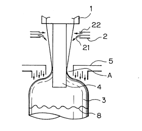
Fig. 1 is a schematic view showing an example of an
inflation film molding method according to the first
embodiment of the present invention;
Fig. 2 is a schematic view showing another example
of the inflation film molding method according to the
first embodiment of the present invention, wherein a
stabilizer diameter is greater than a die diameter;
Fig. 3 is a sectional view showing an example of an
air ring used in the present invention;
Fig. 4 is a schematic view showing an example of an
inflation film molding method according to the second
embodiment of the present invention;
Fig. 5 is a schematic view showing another example
of the inflation film molding method according to the
second embodiment of the present invention, wherein a
stabilizer diameter is greater than a die diameter;
Fig. 6 is a schematic view showing an example of an
inflation film molding method according to the third
embodiment of the present invention;
Fig. 7 is a sectional view showing an example of an
air ring used in the third embodiment of the present
invention;
Fig. 8 is a sectional view showing another example
210U~31
of the air ring used in the third embodiment of the
present invention;
Fig. 9 is a schematic view showing an example of a
low frost line type inflation film molding method
according to the prior art; and
Fig. 10 is a schematic view showing another example
of the low frost line type inflation film molding method
- according to the prior art.
DESCRIPTION OF THE PREFERRED EMBODIMENTS
The thermoplastic resins usable in the present
invention include, for example, polyethylene resins such
as LLDPE, HDPE, LDPE, etc.; copolymer resins between
ethylene and radically polymerizable monomers such as
ethylene-vinyl acetate copolymers, ethylene-acrylate
1~ copolymers, ethylene-methyl methacrylate copolymers,
etc.; polypropylene resins, poly(vinyl chloride), resins;
polyamide resins, polyester resins, and the mixtures
thereof, even though they have a small melt tension.
However, the thermoplastic resins having a higher
molecular weight, which can provide a greater melt
tension, have excellent bubble stability.
According to the present invention, since the bubble
stability is high even in the case of LLDPE, the film can
be taken up at a high speed during molding and the molded
film has excellent transparency and strength, and the
transparency thereof is comparable to that of a casting
polypropylene film. Furthermore, the film according to
the present invention can be used as a less expensive
film usable at a low temperature.
The first and second embodiments of the present
invention will be explained using LLDPE as a typical
example of the thermoplastic resins, with reference to
the accompanying drawings.
The inflation molding method usable in the present
invention may be either upward blowing (see Fig. 2) or
downward blowing (see Fig. 3).
Although the extrusion temperature of the resin
- 2100431
-- 7
varies somewhat depending upon the kind of the resin, the
temperature is generally within the range of a
temperature higher by 40C than the melting point to a
temperature higher by 120C than the melting point. In
the case of LLDPE, for example, the molding is preferably
carried out within the temperature range of 170 to 250C.
When the temperature is lower than 170C, the melt
fracture is likely to occur and when the temperature is
higher than 250C, on the other hand, melt tension
becomes smaller and the bubble stability is deteriorate.
Particularly, LLDPE or a resin composition
containing LLDPE is likely to occur melt fracture.
Therefore, the surface roughening can be avoided by
setting a lip gap of a die to a range of 2.0 to 10.0 mm,
preferably, 2.5 to 5.5 mm, which is greater than in the
case of HDPE, or providing a bubble heater (not shown in
the drawing) for heating the surface of a melt resin
bubble 3 at an intermediate point, which is closer to the
die side than an expansion point between a first air
ring 2 and a second air ring 5. When the lip gap becomes
greater than 7.0 mm, the uniformity of a film thickness
is lost. Therefore, even though the melt fracture can be
reduced by a greater lip gap, the lip gap should not be
greater than 10.0 mm, as it is preferable to avoid skin
roughening of the surface by the bubble heater.
The melt resin bubble 3 extruded at a relatively low
temperature is cooled by cooling air from the first air
ring 2 in the vicinity of the die outlet.
The blowing direction of the cooling air from the
first air ring 2 may be oblique to the take-up direction
in the same way as in the conventional air rings, but is
preferably to a substantially horizontal direction.
Particularly, in the case of an air ring which blows
out air obliquely to the take-up direction, it is
preferred to use a first air ring equipped with a sub air
outlet 22 for supplying a small amount of supplementary
cooling air to compensate for a reduced pressure
2100~31
-- 8
atmosphere to prevent the reduced pressure atmosphere
generated by blow-out of the main cooling air from a main
air outlet 21 from adversely affecting the melt resin
bubbles 3, as shown in Fig. 1 or Fig. 4. Air for the sub
air outlet may be the same air as air for the main outlet
from the same air source, or the blow-out quantity may be
controlled independently. However, the sufficient effect
can be obtained, without the delicate control, because an
allowable range is relatively large within the range in
which the reduced pressure atmosphere does not adversely
affect the melt resin bubbles 3.
It is advisable to provide an outlet internal
stabilizer B having a diameter substantially equal to, or
somewhat greater than, a slit diameter of the die 1, at a
portion to which the cooling air is blown from this first
air ring 2. The outlet stabilizer B may be constituted
by, for example, a plate-like member, a net-like member
or a spring, in order to reduce contact resistance as
much as possible. When the outlet stabilizer B is
provided, the bubble shape of the bubble can be retained
by the outlet stabilizer B even when the blow-out
pressure of the first air ring 2 is high, and this
portion can be effectively stabilized.
According to the first embodiment of the present
invention, the melt resin bubble is cooled by the first
air ring, is taken up, while increasing the melt tension
thereof and rapidly expands after it comes into contact
with the stabilizer.
Preferably, the stabilizer generally has an outlet
stabilizer on the die side thereof and furthermore,
coaxially supports the internal stabilizer, etc., which
is conventionally used for HDPE, at the downstream side
of the outlet stabilizer. In this case, the melt resin
bubble after leaving the outlet stabilizer forms a long
neck type shape and tends to shrink as it is
progressively spaced apart from the outlet stabilizer.
Thus, the melt resin bubble comes into contact with the
2100131
internal stabilizer and becomes stabilized. The diameter
of the internal stabilizer is not specifically limited.
In other words, it may be greater than the die diameter
but preferably, it is smaller than the outlet stabilizer
S diameter and is generally 0.7 to 1.3 times, more
preferably 0.7 to 1.0 times the diameter of the die.
Even when a film having the same size is produced by
using the die having the same size, a substantial
expansion ratio (i.e., bubble diameter after
expansion/bubble diameter before rapid expansion) can be
increased.
According to the second embodiment of the present
invention, to support the bubble in the non-contact state
by the internal stabilizer 4 having the air layer on the
surface thereof, a small amount of air is caused to
continuously flow between the internal stabilizer and the
bubble, generally to the take-up direction of the bubble.
For example, an air inlet 6 is provided at the base
portion of the internal stabilizer 4 while an air
outlet 7 is provided at the top of the internal
stabilizer, and air is caused to flow in such a manner
that the internal pressure of the melt resin bubble can
be controlled to a constant level. Thus, the bubble can
be supported stably by the internal stabilizer 4 in the
non-contact state. In this case, the surface of
the internal stabilizer must be as flat as possible, so
that the disturbance of the air flow can be minimized.
Although the diameter of the internal stabilizer 4
is not particularly limited, the diameter is preferably
smaller than that of the outlet stabilizer B and is from
0.7 to 1.3 times, more preferably, from 0.7 to 1.0 times
the die diameter. This is because a substantial
expansion ratio (i.e., a ratio of the bubble diameter
after expansion to the bubble diameter before expansion)
can be increased even when the film having the same size
is produced from the die 1 having the same size.
On the contrary, the second embodiment of the
~ 2~00431
-- 10 --
present invention demonstrates the merit in that a film
having the same size and the same expansion ratio can be
produced by using a die having a greater diameter.
When the substantial expansion ratio is increased,
there can be obtained the effects that the strength in a
transverse direction (i.e., a rectangular direction to
the film take-up direction~ can be increased and the
impact strength can be increased, as well. The
substantial expansion ratio is generally from l.3 to 6.0
and, preferably, within the range of 1.5 to 4.S.
When the expansion ratio is substantially smaller
than the value described above, a longitudinal rupture is
likely to occur in the resulting film, and the impact
strength drops. When the substantial expansion ratio is
lS more than 6.0, on the other hand, the orientation in the
transverse direction becomes too strong and slicing of
the film is likely to occur, and cut-off of the bubble is
also likely to occur during the production. Therefore,
ratios this high should be avoided.
In the first embodiment of the present invention, a
stabilizer for a HDPE balance film can also be used as
the internal stabilizer according to the present
invention, but it is preferred to use an internal
stabilizer of the type which reduces the contact
resistance, such as a stabilizer having a ball bearing or
a barrel type roller buried at the contact position with
the bubble, a stabilizer using a spring, a stabilizer
equipped with a belt rotating in synchronism with the
film in the film travelling direction, on the surface of
the internal stabilizer, a stabilizer made of Teflon *
having a small frictional resistance, and so forth.
When the contact resistance between an internal
stabilizer 4 and a melt resin bubble 3 is great, the cut-
off of the bubble is likely to occur, because the melt
tension remains at a low level even though it is
increased. For this reason, the internal stabilizer 4
having a small contact resistance should be employed.
* - Trade Mark
~' .
2100~31
The melt resin bubble 3 is supported by the internal
stabilizer 4 by an air layer during the production of the
inflation film according to the second embodiment of the
present invention. Therefore, the contact resistance at
this portion is extremely small; hence, a stable high
speed takeup operation becomes possible even in the case
of the thermoplastic resin bubble having a small melt
tension.
One of the important features of the first and
second embodiments of the present invention is the
temperature of the melt resin bubble. The melt resin
bubble 3 extruded from the die 1 must be cooled by
cooling air, etc., from the first air ring 2 and must
remain within a temperature range which ranges from the
melting point of the resin used to a temperature higher
by 110C than the melting point, at the inlet of the
second air ring 5. Preferably, the above-mentioned
temperature is generally within the range of from
(melting point + 30C) to (melting point + 80C) and more
preferably, from (melting point + 40C) to (melting
point + 80C). When this temperature is less than the
melting point, the melt bubble is only gradually cooled,
accordingly, and as a result, not only does transparency
drop, but expansion becomes impossible or incomplete, so
that the desired non-uniformity becomes large and a film
having a desired thickness and size cannot be obtained.
When the above-mentioned temperature is higher than the
range mentioned above, the expansion of a melt resin
bubble 3 becomes non-uniform and the stability of the
bubble drops. Accordingly, the production of a film
having uniformity becomes more difficult.
In the case of a straight-chain low-density
polyethylene, for example, the resin temperature at the
second air ring inlet should be within the range of 125
to 220C. The melt resin bubble is sufficiently expanded
inside the second air ring 5 or is sufficiently expanded
immediately after it comes out from the second air
21û0431
_ - 12 -
ring 5, to form a film having a desired thickness (e.g.,
10-150~m, more preferably 10-80~m) and size. When ~he
high transparency is required, the film thickness is up
to 50~m and preferably, up to 40~m. As the thickness of
the film increases, cooling becomes more gradual, and the
film unavoidably becomes opaque. This problem can be
solved to a certain extent by using a bubble heater.
- Plural air blowing outlets (52, 53, 54) of coaxial
annular slit of the second air ring 5 for blowing at
least two streams of cooling air may blow out the air to
the outside of the bubble diameter, but if possible, air
is preferably blown out in parallel with the bubble take-
up direction as shown in ~ig. 3.
The blowout of cooling air from the annular slits of
the air ring in the bubble take-up direction generates a
reduced pressure atmosphere. This reduced pressure
atmosphere gives an influence on the melt resin bubble,
and the drastic expansion of the bubble is started at
this position.
Incidentally, although Fig. 3 shows triple
annular slits of the air outlets (52, 53, 54) of the
second air ring 5, but these may be at least double. The
upper end wall surface of each air outlet 52, 53, 54 may
be inclined so as to increase the degree of the reduced
pressure, and a cover 55 may be fitted onto the tip of
the air ring so as to also cut-off the flow of external
air as well as the reduced pressure atmosphere from the
outside.
The position of the frost line 8 that affects the
properties of the resulting film can therefore be changed
freely by the position of the second air ring 5. The
position of the second air ring 5 must generally be
spaced apart by at least 50mm from the die surface,
preferably, by at least lOOmm and more preferably, by at
least 200mm. When the second ring 5 is too close to the
die surface, the cooling effect is decreased and the high
speed take-up operation becomes difficult.
21004~1
As soon as the melt resin bubble 3 is drastically
expanded, the resin film becomes thin, and is accordingly
quenched. After it is solidified, air is squeezed by a
nip roller in the same way as in the case of a
conventional inflation method, and the film is taken up
by a take-up machine to provide a product film.
The first and second embodiments of the present
invention provide a production method which is effective
not only for a thermoplastic resin having a high melt
tension such as HMWHDPE for conventional balance films
but also for those thermoplastic resins for which long
neck type inflation molding has been believed to be
difficult by a conventional inflation molding machine.
The reasons why the resin obtained by the method of
the present invention has high transparency are assumed
to be as follows.
Generally, the melt resin bubble extruded from the
die expands at the outlet due to the swell effect, and
the outer diameter of the melt resin bubble becomes
greater by several to ten several percentage points than
the die diameter, as is well known in the art.
When the bubble is expanded, the bubble surface
shows large concavo-convex conditions. When the film
molding is carried out in the bubble shape having a low
frost line type shown in Fig. 9 or Fig. 10, the film is
drastically expanded from this state and the film surface
is strongly influenced by the swelling effect.
In the case of the long neck type, bubble shape,
however, the melt resin bubble slowly moves towards the
expansion point, the concavo-convex conditions on the
surface thereof formed by swelling are drastically
relaxed and the relaxed bubble is drastically expanded.
Consequently, the influences caused by swelling can be
reduced remarkably, and this is believed to be one of the
factors for providing a film having a flatter surface.
Haze is known as one of the indices of transparency
of films. The major proportion of the haze value of the
2100~31
- 14 -
film is existed in the external haze (i.e., opacity
resulting from non-transmission of light due to concavo-
convexities of the film surface) as is known in the art.
It is believed that the high transparency of the
film according to the present invention is partially
obtained from the long neck type bubble shape, which can
relax the swelling effect.
When a neck point (i.e., a point immediately before
the drastic expansion) is lowered to the crystallization
point, the crystal grows and the haze is adversely
affected. The present invention avoids this problem by
limiting the temperature of the second air ring inlet,
and this is believed to also contribute to the production
of the high transparency film.
It is also believed that, according to the molding
method of the present invention, the inflation molding
can be satisfactory affected by controlling the melt
resin bubble temperature at the inlét of the second air
ring 5 by due to the cooling by the first air ring 2, and
by the application of a method of drastical expanding of
the melt resin bubble in the reduced pressure atmosphere
generated by blow-out of the cooling air from a plurality
of annular slits (52, 53, 54) of the second air ring,
both for a resin having a high melt tension and even for
a resin having a low melt tension.
Particularly, the melt resin bubble can be
stabilized by supporting the same with the stabilizer in
contact therewith in the first embodiment of the present
invention or by supporting the same with the stabilizer,
while non-contact therewith, in the second embodiment,
and the high speed take-up operation becomes possible due
also to the improvement in the cooling capacity due to
the use of two stages of the air rings. Furthermore, due
to the synergistic effect with quenching of the melt
resin resulting from the drastic expansion, transparency
such as the haze and image clarity can be remarkably
improved.
2100431
- 15 -
As mentioned above, in the film molding of the
thermoplastic resin by the inflation method, the first
and second embodiments of the present invention gradually
cool the molten resin bubble by the first air ring
provided at the vicinity of the die outlet; support it by
the stabilizer in the contact state (i.e., the first
embodiment) or support it by stabilizer, while in non-
contact state with the surface of the stabilizer via the
air layer (i.e., the second embodiment); control the
temperature of the inlet of the second air ring having a
plurality of annular slits to the range from the melting
point of the thermoplastic resin to a temperature higher
by 100C than the melting point; stabilize the melt resin
bubble even in the case of the thermoplastic resin having
a small melt tension such as LLD during a long neck type
film molding; and can produce a film having excellent
transparency (i.e., haze and clarity) at a high speed.
The molding apparatus used for this purpose can also
be used suitably for the inflation film molding method
mentioned above.
Furthermore, the present inventors found that, even
in the case of those thermoplastic synthetic resins which
are likely to undergo melt fracture, the haze and clarity
can be drastically improved by producing the film by
disposing the bubble heater between the first and second
air rings.
Next, the third embodiment of the present invention
will be explained with reference to drawings for the case
of LLDPE as a typical example of the thermoplastic
resins.
The inflation molding method usable for the present
invention may be either upward blowing or downward
blowing.
According to the third embodiment of the present
invention, the resin extrusion temperature is relatively
low because the air ring 5 in the vicinity of the die 1
does not exist. Although the extrusion temperature
21004~1
- 16 -
-
varies somewhat depending upon, the kind of the resin, it
is within the range of from a temperature higher by 40C
than the melting point to a temperature higher by 120C
than the melting point, preferably within the range of
~ 5 from (melting point + 40C) to (melting point + 80C).
In the case of LLDPE, for example, the molding is
preferably carried out within the temperature range of
from 170C to 210C. When the temperature is less
than 170C, the melt fracture is likely to occur and when
the temperature is more than 210C, on the other hand,
the melt tension becomes so small that the stability of
the bubble 3 is likely to be deteriorated.
In this case, LLDPE or a resin composition
containing LLDPE is likely to undergo the melt fracture
when it is extruded at a low extrusion temperature, and
the skin roughening of the surface can be avoided by
increasing the lip gap of a die 1 to 2.0 to lO.Omm
(preferably, 2.5 to 5.5mm), which is greater than that of
the case of HDPE, or by disposing a bubble heater (not
shown) for heating the surface of a melt resin bubble 3
at an intermediate point (on the die side with respect to
the expansion point) between the die 1 and an air ring 5.
The uniformity of the film thickness is lost with the
increase in the lip gap from more than 7.Omm. Therefore,
even though the melt fracture can be reduced, the lip gap
should not be increased beyond lO.Omm, and the skin
roughening of the surface is preferably avoided by the
bubble heater.
The melt resin bubble 3 extruded at a relatively low
temperature is taken up, while the inner surface thereof
is kept in contact with a stabilizer 4. In this case, it
is advisable to provide an outlet stabilizer B equal to,
or somewhat greater than, the slit diameter of the die
supported coaxially with a conventional internal
stabilizer, on the die side of the internal stabilizer.
To reduce the contact resistance as much as possible, the
outlet stabilizer B may be constituted by a sheet- or
2100431
- 17 -
net-like member, a spring, and so forth. When such an
outlet stabilizer B exists, the bubble shape of the
bubble 3 is retained by the outlet stabilizer B, and this
portion can be further stabilized. The melt resin
bubble 3 is taken up, and after coming into contact with
the internal stabilizer 4, the bubble 3 is drastically
expanded.
- The stabilizer generally has the outlet stabilizer B
on the die side, and more preferably has the internal
stabilizer 4, which is conventionally used for HDPE,
supported coaxially on the downstream side of the
stabilizer B. In this case, the melt resin bubble 3
leaving the outlet stabilizer B assumes is the form of a
long neck type shape, and as it comes off from the outlet
stabilizer, it tends to shrink. Therefore, the melt
resin bubble comes into contact with the internal
stabilizer and becomes stabilized. The diameter of the
internal stabilizer is not particularly limited, and may
be greater than the die diameter but is preferably
smaller than the outlet stabilizer and generally 0.7 to
1.3 times the die hole diameter. Thus, even when the
film of the same size is produced by using a die having
the same size, a substantial expansion ratio (i.e.,
bubble diameter after expansion/bubble diameter before
expansion) can be increased. On the contrary, there can
be obtained the merit in that a film having the same
expansion ratio and having the same size can be produced
by using a die having a greater diameter.
When this substantial expansion ratio is increased,
there can be obtained the effects that the strength in
the transverse direction (i.e., direction orthogonal to
the film take-up direction) can be increased and the
impact strength can be improved, as well. The
substantial expansion ratio is generally within the range
of 1.3 to 6.0 and preferably, within the range of 1.5
to 4.5.
When the expansion ratio is substantially smaller
2100431
- 18 -
than this range, the resulting film is likely to undergo
longitudinal rupture, and the impact strength also
becomes lower. When the substantial expansion ratio is
greater than 6.0, on ther other hand, the orientation in
the transverse direction becomes so excessive that
slicing of the film is likely to occur and cut-off of the
bubble is also likely to occur during the production.
Therefore, these ranges should be avoided.
Although a stabilizer for any HDPE balance film can
be used as the internal stabilizer 4, it is preferred to
use an internal stabilizer of the type which reduces the
contact resistance, such as a stabilizer having a ball
bearing or a barrel type roller buried at the contact
position with the bubble, a stabilizer using a spring, a
stabilizer equipped with a belt rotating in synchronism
in the film travelling direction on the surface of the
internal stabilizer, and so forth.
When the contact resistance is large between the
internal stabilizer 4 and the melt resin bubble 3, cut-
off of the bubble is likely to occur because the
improvement in the melt tension, although it is attained,
is only at a limited level. Therefore, the internal
stabilizer 4 having a smaller contact resistance should
be employed.
The melt resin bubble temperature is one of the
important factors in the present invention. The melt
resin bubble 3 extruded from the die 1 at a relatively
low temperature should be within a range from the
crystallization point of the resin used to a temperature
higher by 60C than the crystallization point, at the
outlet of the air ring, and is preferably within the
range of (crystallization point + 10C) to
(crystallization point + 40C). When the melt resin
bubble temperature is lower than the crystallization
point, the melt bubble is only gradually cooled so that
the transparency is decreased, and moreover, the
expansion becomes impossible or incomplete. Accordingly,
2100431
- 19 -
-
- variance becomes large and a film having an intended
thickness and size cannot be obtained. When the
temperature is higher than the above-mentioned
temperature range, the expansion of ~he melt resin
S bubble 3 becomes non-uniform and the stability of the
bubble is deteriorated. Accordingly, the production of a
uniform film becomes difficult. Generally, the
crystallization point of the thermoplastic resins exist
at a temperature lower by about 10C than the melting
point thereof.
In the case of a linear low density polyethylene,
for example, the resin temperature at the outlet of the
air ring should be from the melting point of the
thermoplastic resin to 180C (e.g., 120-180C) . The
lS melt resin bubble is sufficiently expanded in the air
ring, or is sufficiently expanded immediately after it
comes out from the air ring, and is converted to a film
having a predetermined thickness (e.g., 10-lSO~m, more
preferably 10-80~m) and size. When the high transparency
is required, the film thickness is not greater than 50~m,
preferably not greater than 40~m. As the film thickness
becomes larger, the film is cooled more gradually, so
that the film unavoidably becomes opaque. This problem
can be solved to a certain extent by the use of a bubble
heater, as mentioned above.
The outlets of a plurality of annular slits
(52, 53, 54) of the air ring having the concentric
annular slits for blowing out at least two cooling air
streams may blow out the air in the onward direction of
the bubble diameter, but are preferably shaped in such a
manner as to blow out the air in the direction
substantially parallel to the bubble take-up direction as
shown in Fig. 7 or Fig. 8.
The reduced pressure atmosphere which is generated
by blow-out of the cooling air from the annular
slits (52, 53, 54) of the air ring 5 affect the melt
resin bubble, and the drastic expansion of the bubble
21004~1
- 20 -
starts to occur at this position.
Fig. 7 or Fig. 8 shows the cooling air outlets of
the annular slits (52, 53, 54) of the air ring S in the
triple annular slit structure, but this may be at least a
double structure. The upper end wall surface of each air
outlet of the annular slits (52, 53, 54) may be inclined
so as to increase the degree of the reduced pressure
atmosphere. A cover 55 may also be fitted to the tip of
the air ring so as to cut-off the flow of external air
and cut-off the reduced pressure atmosphere from the
outside.
Accordingly, the position of the frost line, which
affects the properties of the resulting film, can be
changed freely by moving the position of the air ring 5.
The position of the air ring 5 should generally be spaced
apart by at least 50mm from the die surface, preferably
by at least lOOmm, and more preferably by at least 200mm.
The cooling effect is decreased when the distance is too
close to the die surface.
To promote cooling of the melt resin bubble 3, it is
also effective to use an air ring having outlets 57 (see
Fig. 8) for cooling the melt resin bubble in the opposite
direction (i.e., the melt resin bubble ranging from the
die to the air ring) in addition to the outlets of a
plurality of the annular slits (52, 53, 54) for the
cooling air in the bubble take-up direction. This method
can increase the extruded resin temperature, although to
a limited extent, can somewhat relax the operation
condition, and can improve productivity. The outlets 57
in the opposite direction are not limited, and cooling
air can be blown to the melt resin bubble at an angle of
from 45 to 60.
When the melt resin bubble 3 is drastically
expanded, the resin film becomes thin. Accordingly, the
film is quenched. After the film is solidified, air is
squeezed by nip rollers (not shown in the drawing) in the
same way as in the conventional inflation, and the film
210~4~1
is taken up by a take-up machine to provide a product
film.
The present invention provides a production method
which is effective for not only the thermoplastic resin
-having a high melt tension such as HMWHDPE for ordinary
balance films, but also for those thermoplastic resins
which have a low melt tension and for which long neck
type inflation molding has been believed to be difficult.
The reasons why the film obtained according to the
method of the present invention has high transparency are
believed to be as follows.
Generally, the melt resin bubble extruded from the
die expands at the outlet due to the swelling effect, and
the outer diameter of the melt resin bubble becomes
larger by several to ten several percentage points than
the die diameter, as is well known in the art.
When the melt resin bubble expands due to the
swelling effect, the bubble surface has a large number of
concavo-convexities. When the film molding is carried
out in the low frost line type bubble shape, shown in
Fig. 9 or Fig. 10, the bubble is drastically expanded
from that state. Accordingly, the film surface receives
a strong influence from the swelling effect.
In the case of the long neck type bubble, however,
the melt resin bubble slowly moves to the expansion point
and in the mean time, the concavo-convexities generated
on the surface due to the swelling effect are drastically
relaxed, and since this relaxed bubble is drastically
expanded, the influence from the swelling can be
drastically reduced. This is believed to be one of the
reasons why a film having a flatter surface can be
obtained.
Haze is one of the indices of transparency of films.
It is known that the major proportion of the haze value
of a film consists mostly of external haze (i.e., opacity
due to non-transmission of light due to concavo-
convexities on the film surface).
21004~1
- 22 -
It is believed that the high transparency of the
film according to the present invention is partially
brought forth by the long neck type bubble which relaxes
the swelling effect.
When the neck point (i.e., the point immediately
before drastic expansion) is lowered to the
crystallization point, the crystal grows, and the haze is
deteriorated. However, the present invention avoids this
problem by controlling the temperature at the inlet of
the air ring, and this is believed to be one of the
factors for obtaining the high transparency film.
Although the reasons have not yet been sufficiently
clarified, according to the molding method of the present
invention, the inflation molding can be effected for not
only resins having a high melt tension but also for
resins having a low melt tension, without any practical
problems, by controlling the temperature of the melt
resin bubble at the outlets of the air ring 5, and by
drastically expanding the melt resin bubble in the
reduced pressure atmosphere generated by blow-out of the
cooling air from a plurality of annular slits of the air
ring.
In particular, because the melt resin bubble is
brought into contact with the stabilizer, the melt resin
bubble is stabilized, and optical characteristics such as
haze, gloss, clarity, etc., can be remarkably improved by
the synergistic effect obtained from quenching of the
melt resin due to the drastic expansion.
In film molding of the thermoplastic resin by the
inflation method, the present inventors found that even
in the case of those thermoplastic resins having a low
melt tension, such as LLDPE, the melt resin bubble can be
stabilized and a film having excellent optical
characteristics such as haze, gloss and clarity can be
stably produced by supporting the melt resin bubble in
contact state with the stabilizer, controlling the
temperature of the outlets of the air ring having a
2100431
- 23 -
-
plurality of annular slits provided at the position of
the drastic expansion of the bubble to a temperature
range from the crystallization point of the thermoplastic
resin to a temperature higher by 60C than the
crystallization point, and carrying out molding of the
film by the long neck type molding method.
The molding apparatus used for this purpose can be
suitably applied to the inflation film molding method as
mentioned above.
Furthermore, the present inventors found that the
haze, gloss and clarity can be drastically improved even
in the case of the thermoplastic synthetic resins, which
are likely to undergo the melt fracture, by disposing the
bubble heater between the die and the air ring.
EXAMPLES
The present invention will now be further
illustrated by, but is by no means limited to, the
following Examples.
Example 1-1
A linear polyethylene having a density of
0.923 g/cm3 and a melt flow rate (hereinafter referred to
as "MFR") according to JIS K-7210, Table 1, Condition 4
of 1.0 g/10 min, was extruded at a resin temperature of
200C, using an inflation film molding apparatus provided
with a die having a lip gap of 3 mm and a diameter of
100 mm~.
A circular cylinder having the surface thereof
coated with Teflon and having a diameter of 100 mm~ was
used as the stabilizer, and a film having a lay-flat
width of 314 mm and a thickness of 30 ~m was molded at a
take-up speed of 50 m/min. The melt resin bubble was
cooled by cooling air, etc., from the first air ring.
The melt resin temperature was 167C at the inlet of the
second air ring consisting of double annular slits and
was 131C at the outlet. The frost line was 650 mm from
the die surface, and the frost line temperature was
111C. Evaluation results of the resulting film are
210~4~
- 24 -
shown in Table 1-1.
The temperature of the second air ring inlet was
measured at the nearest portion to the air ring by the
use of an IR-AP thermometer, a product of Chino K.K., at
a distance of 150cm and a measurement area of a diameter
of 45 mm~. The haze, gloss and clarity were measured by
the methods according to JIS K-7105.
Examples 1-2 to 1-5
Molding of films were carried out using a resin
composition consisting of 80 wt% of LLDPE having a
density of 0.923 g/cm3 and an MFR of 1.0 g/10 min and
20 wt% of LDPE having a density of 0.925 g/cm3 and an MFR
of 0.8 g/10 min and using the same apparatus as that of
Example 1-1 but changing the molding condition.
Evaluation results of the resulting films are shown in
Table 1-1.
Example 1-6
Molding of a film was carried out using a resin
composition consisting of 60 wt% of HDPE having a density
of 0.953 g/cm3 and an MFR of 0.5 g/10 min and 40 wt% of
LDPE having a density of 0.925 g/cm3 and an MFR of
0.8 g/10 min and using the same apparatus as that of
Example 1-1 at a resin temperature of 200C and under the
molding condition shown in Table 1-1. Evaluation results
of the resulting film are shown in Table 1-1.
Example 1-7
Improvement in transparency was attempted in film
molding of Example 1-4 by disposing a 3.0 kW infrared ray
heater (i.e., bubble heater) at an intermediate portion
between the first air ring and the second air ring.
Evaluation results of the resulting film are shown in
Table 1-1. Table 1-1 illustrates that the transparency
(i.e., haze, gloss and clarity) could be remarkably
improved.
Comparative Example 1-1
Molding of a film was carried out using the same
resin and the same apparatus as those of Example 1-2
2100431
- 25 -
under the condition shown in Table 1-1. Transparency
(i.e., haze, gloss and clarity) of the resulting film is
remarkably decreased.
Comparative Examples 1-2 to 1-4
Inflation film molding of a low frost line type
bubble (i.e., the bubble shape shown in Fig. 10 or
Fig. 11), in which the melt resin bubble immediately
expanded from the die outlets, was carried out using the
same resin as that of Example 1-2. Evaluation results of
the resulting film are shown in Table 1-1.
In Comparative Examples 1-2 and 1-3, the decrease in
the transparency was not large, but even when the frost
line in Comparative Example 1-3 was substantially the
same as that of Example 1-1, the mechanical properties of
the film are remarkably decreased. When the take-up
speed was set to the same value of 50 m/min as in
Examples 1~ 2, 1-4 and 1-7, the melt resin bubble
became unstable and the breakage occurred so frequently
that the molding operation became impossible.
- 26 - 2100~31
~ , ~ o o o o ~ oo o U~
E~ ~n ~ ~i O~ ~ O
a~
~,~ ~ ~ o a~ ~ oo o~ ~ ~ o
J 00
n ~ ,.
! ~
L ~ ~I ~ c~ 1 0 ~ t``l ~ a~, ~
~n
~n
0 3~ ~~ ~ ~ ~ ~ ~ o
o o o o o o o o o o
~1
a~ ~
o o u~ o o o o ~ o o o
E~ ~n
o U~ o U7 o o U~ o o o o
.
~ ~ ~ O c~l ~( ~1 a~ ~1 0
a) ~ O ~ ~ ~1 ~ ~1 ~ ~1 0 ~ ,1
.,1 E~
o 3 o o o o o o o o o o o
~ O 0 0~ o ~ U'~
.
~,~ I~ ~ C~l o C~ ~ o o ~ ~
o o
~! ~ ~ t~ t~ t~ t~ ~ ~ ~1 ~I t~
V JJ V
a, ~ a,
~3 ~
2100~1
~ 27 -
Example 2-1
A linear polyethylene having a density of
0.923 g/cm3 and an MFR according to JIS K-7210, Table 1,
Condition 4, of 1.0 g/10 min was extruded at a resin
temperature of 200C using an inflation film molding
apparatus provided with a lip gap of 3mm and a diameter
of lOOmm~.
A circular cylinder having the surface thereof
coated with Teflon and having a diameter of lOOmm~ was
o used as the stabilizer, and a film having a lay-flat
width of 314 mm and a thickness of 30~m was molded at a
take-up speed of 50 m/min, while the melt resin bubble
was supported under the non-contact state and while a
small amount of air was supplied from the base portion of
the stabilizer. The melt resin bubble was cooled by
cooling air, etc., from the first air ring. The
temperature was 162C at the inlet of the second air ring
consisting of a double annular slit, and the frost line
was 620mm from the die surface. Evaluation results of
the resulting film are shown in Table 2-1.
The temperature at the inlet of the second air ring
was measured at the nearest portion to the air ring by
the use of an IR-AP thermometer, a product of Chino K.K.,
at a distance of 150cm and a measurement area of a
diameter of 45mm~. The haze, gloss and clarity were
measured by the method according to JIS K-7105.
Examples 2-2 to 2-5
Molding of films was carried out using a resin
composition consisting of 80 wt~ of LLDPE having a
density of 0.923 g/cm3 and an MFR of 1.0 g/10 min and
20 wt% of LDPE having a density of 0.925 g/cm3 and an MFR
of 0.8 g/10 min and the same apparatus as that of
Example 2-1, but changing the molding condition.
Evaluation results of the resulting films are shown in
Table 2-1.
Example 2-6
Molding of a film was carried out using a resin
21~043~
- 28 -
.
composition consisting of 60 wt% of HDPE having a density
of O.9S3 g/cm3 and an MFR of 0.5 g/lO min and 40 wt% of
LDPE having a density of 0.925 g/cm3 and an MFR of
0.8 g/lO min and the same apparatus as that of
Example 2-1, at a resin temperature of 200C and under
the molding condition shown in Table 2-l. Evaluation
results of the resulting film are shown in Table 2-1.
Example 2-7
Improvement of transparency was attempted in molding
lo of the film in Example 1-4 by disposing a 3.0 kW infrared
heater (bubble heater) at an intermediate portion between
the first air ring and the second air ring. Evaluation
results of the resulting film are shown in Table 2-1.
Table 2-l illustrates that the transparency (haze, gloss
and clarity) could be remarkably improved.
Comparative Example 2-1
Molding of a film was carried out using the same
resin and the same apparatus as those of Example 2-2
under the condition shown in Table 2-l. The transparency
zo (haze, gloss and clarity) of the resulting film was
remarkably decreased.
Comparative Examples 2-2 to 2-4
Inflation film molding of a low frost line type (the
bubble shape shown in Fig. 9 or Fig. 10), in which the
melt resin bubble immediately expanded from the die
outlet, was carried out using the same resin as that of
Example 2-2. Evaluation results of the resulting films
are shown in Table 2-1.
The decrease in the transparency was slight in
Comparative Examples 2-2 and 2-3. When the frost line
was made substantially the same as Examples of the
invention such as in Comparative Example 2-3, however,
the mechanical properties of the films are remarkably
decreased. When the take-up speed was set to the same
speed of S0 m/min as that of Examples 2-1, 2-2, 2-4 to
2-7, the bubble became unstable and breakage occurred so
frequently that molding operation became impossible.
Table 2-1
Lip AR2 Frost line BUR Take-up Film
gap inlet speed
temp.
Distance Temp. Thickness Haze Gloss Clarity Impact Tear
strength strength
mm C mm C m/min ~m ~ ~ % kg.cm/mm MD TD
Examples 2-1 3.0 162 620 111 2.0 50 30 4.1 121 74 226 10.5 187
2-2 3.0 168 780 111 2.5 5030 4.6 117 72 228 12.1 165
2-3 3.0 171 820 111 2.0 6530 4.6 119 73 219 9.8 196
2-4 3.0 168 900 110 1.5 5050 6.5 114 69 208 14.5 228
2-5 5.0 143 710 111 2.0 5030 4.6 122 74 239 9.5 195
2-6 3.0 l9S 680 121 2.0 5030 4.1 121 68 185 23.8 195
2-7 3.0 190 920 lll 1.5 5050 3.8 126 71 215 15.2 231
Comparative
Examples 2-1 3.0 120 700 109 2.0 23 30 16.2 68 52 266 20.0 138
2-2 3.0 - 350 111 2.0 3030 ~4.9 120 73 210 6.5 181 ~ ~
2-3 3.0 - 650 llO 2.0 3030 6.7 106 69 206 6.2 187 O
2-4 3.0 - 350 - 2.0 50 molding was not possible ~
2100~1
- 30 -
Example 3-1
A linear polyethylene having a density of
0.923 g/cm3 and an MFR according to JIS K-7210, Table 1,
Condition 4, of 1.0 g/10 min was extruded at a resin
s temperature of 200C using an inflation film molding
apparatus provided with a lip gap of 3mm and a diameter
of lOOmm~.
A circular cylinder having the surface thereof
coated with Teflon and having a diameter of lOOmm~ was
o used as the stabilizer, and a film having a lay-flat
width of 314mm and a thickness of 30~m was molded at a
take-up speed of 50 m/min. The melt resin bubble had a
temperature of 130C at the outlets of the air ring
consisting of double annular slits. The frost line was
650mm from the die surface, and the frost line
temperature was 111C. Evaluation results of the
resulting film are shown in Table 3-1.
The temperature at the inlet of the air ring was
measured at the nearest portion to the air ring by an
IR-AP thermometer, a product of Chino K.K., at a distance
of 150cm and a measurement area of a diameter of 45mm~.
The haze, gloss and clarity were measured by the method
according to JIS K-7105.
Examples 3-2 and 3-3
Molding of films was carried out using a resin
composition consisting of 80 wt% of LLDPE having a
density of 0.923 g/cm3 and an MFR of 1.0 g/10 min and
20 wt% of LDPE having a density of 0.925 g/cm3 and an MFR
of 0.8 g/10 min and the same apparatus as that of
Example 3-1 but changing the molding condition.
Evaluation results of the resulting films are shown in
Table 3-1.
Example 3-4
Improvement in transparency was attempted in film
molding of Example 3-2 by changing the take-up speed to
30 m/min and disposing a 3.0 kW infrared heater (i.e.,
2100431
bubble heater) at an intermediate portion between the die
and the air ring. Evaluation results of the resulting
film are shown in Table 3-1. Table 3-1 illustrates that
the transparency (haze, gloss and clarity) could be
remarkably improved.
Example 3-5
Molding of a film was carried out using a resin
composition consisting of 60 wt~ of HDPE having a density
- of 0.953 g/cm3 and an MFR of 0.5 g/10 min and 40 wt% of
LDPE having a density of 0.925 g/cm3 and an MFR of
0.8 g/10 min and the same apparatus as that of
Example 3-1 at a resin temperature of 200C under the
molding condition shown in Table 3-1. Evaluation results
of the resulting film are shown in Table 3-1.
ComParative Example 3-1
Molding of a film was carried out using the same
resin and the same apparatus as those of Example 3-2.
The transparency (haze, gloss and clarity) of the
resulting film was remarkably decreased.
ComParative Examples 3-2 to 3-4
Inflation film molding of a low frost line type (the
bubble shape shown in Fig. 9 or 10), in which the melt
resin bubble immediately expanded from the die outlet,
was carried out using the same resin as that of
Example 3-2. Evaluation results of the resulting films
are shown in Table 3-1.
The decrease in the transparency was slight in
Comparative Examples 3-2 and 3-3, but even when the frost
line was set to be substantially the same as that of
Example 3-1 such as in Comparative Example 3-3, the
mechanical properties of the resulting films were
remarkably decreased. In Comparative Example 3-4, when
the take-up speed was changed to 50 m/min, while keeping
the same bubble shape, the melt resin bubble became
unstable and the breakage occurred so frequently that the
molding operation became impossible.
2100431
-- 32 --
~ , o o o ~o ~ o ~ .,~,
rv J ~ ......... ...
E~ n ~; r~ O a~ ~ r o ~
a a
r,~ r,~l o r,~ rJ~~D ~( o L
J r,~ r,~ r,~ ~ ,Ir,~ r,~ r,~ ~
--I 04 rn
~ n ,~: O
'~ rd ~ ~ O
~4 _I rn
.~ 3
rn ~ r,~ o u~ r.~ Cl~ O ~D
O ;1~! r.~l r.~ l r.~l r.~ O '-
C~
r~O r.~ r.
rrJ ~e ~ ~ ~ r~ ~
~,
cn
rn
O o o O O o o O
a~ 5
L~ i u~ o O r o O O
E~ rn
F~ o u7 o O o O o O o
p ..... ...
.
~ ~1 ~ O ~ ~rJ~ ~ O
rJ~ ~ 0 7~1 ~ ~1 ,I r.~O ~1 ~(
r~ ~ ~ ~ ~ ~ ~ ~1 ~1
n~
I
rn O O O o oO o O O
~ u7 o u7 r,~ ~7 o u7 u7 u7
n ~ ~D ~ 0 ~ ~7r. r.~7 u7 ~t7
V V
Q~ ~ O r,~ Q7 O u7 r~ rn rn
c 7 ~ r,~ r,~7
o ,~ ,1 ,1 ~1 ~1 'I V ~
O O
,~ r~ rt7 r.~7 u7 r.~7 r.~7 r.~7 r.~7 r.~7
01,7
~1 r.~ r~7 ~ u7 ,I r,~ r~
rl~ I I I I
~7 r.~7 ~7 ~7 r.~7 ~ r.~7 r,~7 r.~7 r.~7
r,7 ~ rrJ
r~ r.~ ~
~ 4 L4
~_ ~7 ~_