Note: Descriptions are shown in the official language in which they were submitted.
2100S25
REMOVABLE MAGNETIC ZERO/SPAN ACTUATOR
FOR A TRANSMITTER
BACKGROUND OF THE INVENTION
1. Field of the Invention.
The present invention relates to transmitters used in
industrial process control systems and more particularly to
the magnetic actuation of the zero and span adjustments of
such transmitters.
2. Description of the Prior Art.
Two-wire transmitters (as well as three-wire and four-
wire transmitters) find widespread use in industrial process
control systems. A two-wire transmitter includes a pair of
terminals which are connected in a current loop together
with a power source and a load. The two-wire transmitter
is powered by the loop current flowing through the current
loop, and varies the magnitude of the loop current as a
function of a parameter or condition which is sensed. Three
and four wire transmitters have separate leads for supply
current and outputs. In general, the transmitters comprise
energized electrical circuits which are enclosed in a sealed
housing such that ignition of any combustible atmosphere by
faults or sparks from the energized circuit is contained in
the housing.
Although a variety of operating ranges are possible,
the most widely used two-wire transmitter output varies from
4 to 20 milliamperes as a function of the sensed parameter.
It is typical with a two-wire transmitter to provide
adjustment of the transmitter so that a minimum or zero
value of the parameter sensed corresponds to the minimum
output (for example a loop current of 4 milliamperes) and
that the maximum parameter value to be sensed corresponds
to the maximum output (for example 20 milliamperes).
The minimum and maximum parameter values will vary from
one industrial process installation to another. It is
desirable, therefore, to provide some means for setting the
maximum and minimum output levels in the field, and this is
done typically with electrically energized zero and span
;, ~ ~
2 2100525
potentiometers sealed in the housing. With some
transmitters, a housing cover must be removed to gain access
to the potentiometers for adjustment, undesirably exposing
the atmosphere surrounding the transmitter to the live
circuits in the transmitter.
A variety of techniques are available for adjusting the
potentiometers while sealing potentially explosive
atmospheres surrounding the transmitter from the
electrically live circuits in the transmitter. In some
transmitters, a rotary adjustment shaft for adjusting a
potentiometer is closely fitted through a bore in the
housing to provide a long flame path for quenching ignition
in the housing before it reaches the atmosphere surrounding
the housing. In yet another arrangement, the potentiometers
are mechanically coupled to a relatively large bar magnet
which is then rotated magnetically by another bar magnet
outside the live circuit's enclosure. This arrangement with
bar magnets can have the disadvantage of mechanical
hysteresis, making precise span and zero setting difficult.
Actuated switches are also used for setting span and zero
in transmitters, such switches requiring an opening through
the wall of the transmitter's housing to provide for
mechanical coupling to the switch.
For many process control environments, the transmitter
itself is required to have an explosion-proof enclosure.
This means that, if a spark takes place inside of the
transmitter housing which ignites gases within the housing,
no hot gases should be propagated from the interior of the
transmitter to the exterior which could cause any
surrounding combustible atmosphere to ignite.
Providing for zero and span adjustments which are
accessible from outside the transmitter (so that the housing
would not have to be opened) is desirable, but makes it
difficult (or expensive) to maintain the explosion-proof
characteristics of the transmitter. One arrangement for
adjusting the zero and span of a transmitter from outside
3 2100525
of the housing is suggested in U.S. Patent No. 4,783,659
("the '659 Patent") which issued on November 8, 1988. The
transmitter described in the '659 Patent includes a
communications circuit which can take a variety of forms
including, as is shown in Fig. 1 of the '659 Patent,
magnetically actuated reed switches which are activated with
a magnet from outside of the transmitter. The '659 Patent
does not further show or describe the magnet or any
structure for using the same to activate the reed switches.
In addition to the actuator disclosed in the '659
Patent, other external span and zero actuators have, in the
past, needed either bulky magnet pairs for transmitting
rotational force or passages formed through the transmitter
housing wall, so that one end of the actuating mechanism
extends into the chamber which contains the transmitter
electronics, while the other end is accessible from the
exterior of the transmitter. In order to maintain
explosion-proof characteristics, very long flame paths must
be created with very tight tolerances. It is also important
that the passages be sealed so that moisture cannot enter
the transmitter housing through the span and zero actuator
passages.
As can be appreciated from the above, it would be
desirable in providing for zero and span adjustments which
are accessible from outside of the transmitter housing to
eliminate the need for a long flame path and very tight
tolerances. A transmitter which has externally accessible
zero and span adjustments without the need for a long flame
path and very tight tolerances is described in International
Application Number PCT/US88/03280 which was published on 5
May 1989 as International Publication Number WO89/04014
("the 03280 PCT application").
The transmitter described in the 03280 PCT application
has zero and span magnetically actuated reed switches
located in an interior chamber of the housing adjacent the
housing's center wall. A relatively flat surface on the
.. ,
4 2100525
exterior of the transmitter housing has a recess formed
therein. A pair of internally threaded blind holes extend
downward from the recess into the center wall of the
housing. A movable permanent magnet is situated in each
blind hole. Each magnet is press fit into a lower recess
of an associated screw which extend down into the associated
blind hole. A spring is coaxially mounted on each magnet.
A rubber washer is positioned below the head of each screw
to provide an environmental seal for the blind hole. Access
lo to the screws from the exterior of the housing is provided
by a plate which is removably attached to the flat surface
by a pair of screws.
Adjustment of the zero and span settings for the
transmitter described in the 03280 PCT application is
accomplished by first removing the plate with a screwdriver
to thereby allow a technician to have access to the upper
ends of the screws associated with the zero and span movable
magnets. The technician can then reset the zero and span
settings of the transmitter by using a screwdriver to loosen
the screws. The spring associated with the screw is under
compression and the loosening of the screw allows the spring
to push the screw up so that the centerline of the magnet
is aligned with the centerline of the associated reed
switch. The electronics to which the reed switches are
connected then adjusts the zero or span settings of the
transmitter. After adjusting the zero and span settings of
the transmitter the technician should tighten the screw to
recompress the spring and move the centerline of the magnet
out of alignment with the centerline of the reed switch.
In addition, the technician should reattach the plate to the
flat surface.
While the transmitter described in the 03280 PCT
application does eliminate the need for a long flame path
and very tight tolerances, it does not limit access to the
movable magnets to only the personnel trained to perform the
zero and span adjustments. The magnets are accessible to
.,~ "~; ' ''
, ,-
~, .
2100525
any individual who has access to the transmitter and ascrewdriver. This makes the adjustment of the zero and span
setting of the transmitter subject to tampering.
According to the 03280 PCT application the adjustment
of the zero and span setting of the transmitter described
therein may be made resistant to tampering by removing the
screws and magnets as well as the associated return springs
and rubber washers from the housing. The screws, magnets,
return springs and rubber washers are relatively small parts
and may be easily lost or misplaced if removed from the
blind holes. As described above, the rubber washers provide
an environmental seal for the blind holes. The rubber
washer does not provide an environmental seal for the moving
parts of the zero or span adjustment mechanism during the
adjustment of the zero or span settings because the washer
is moved away from its sealing face when the screw is moved.
Use of the adjustment mechanism may then allow environmental
contaminants to accumulate in each blind hole. The
accumulated environmental contaminants may cause a
malfunction of the moving parts. Removal of the washers may
expose the internal threads of the blind holes to conditions
which may make it difficult to loosen and tighten the screws
(and therefore adjust the zero and span settings of the
transmitter) when the screws are reinserted into the holes.
Description of the Drawinq
Fig. 1 shows the first embodiment for the magnetic zero
and span actuator of the present invention in conjunction
with a pressure transmitter.
Fig. 2 shows a portion of the pressure transmitter of
Fig. 1 and the location of the zero and span reed switches
internal to the pressure transmitter.
Fig. 3 shows an exploded perspective for the first
embodiment of the magnetic zero and span actuator of the
present invention.
Fig. 3a shows an enlargement of the actuating pin of
one of the actuating arms engaging the associated one of the
:,j,,
~i~
210052S
two slots in the magnet carrier in the first embodiment of
the actuator of the present invention.
Figs. 4a and 4b are sections taken through the first
embodiment of the actuator of the present invention with the
top cover of the actuator housing removed to show in Fig.
4a the position of the actuator arms and magnet carrier when
the actuator is in its null position and in Fig. 4b the
position of the actuator arms and the magnet carrier when
one of the actuator arms is actuated to reset the span of
the pressure transmitter.
Fig. 5 is another section taken through the first
embodiment of the actuator showing the high coercivity
magnet in assembled relationship with the magnet carrier.
Fig. 6 shows an exploded perspective for a second
embodiment of the magnetic zero and span actuator of the
present invention.
Fig. 7 shows the subassembly of the hub and the return
spring used in the second embodiment for the actuator.
Fig. 8 shows the roof of the top cover of the second
embodiment for the actuator.
Fig. 9 shows the bottom of the hub.
Fig. 10 shows an enlargement of the lock spring and hub
interface when the second embodiment for the actuator is
assembled and is in the null position.
Fig. 11 shows a section through the assembled second
embodiment for the actuator with the hub in the null
position.
Fig. 12 shows a simplified section through the second
embodiment for the actuator with the high coercivity magnet
and the magnet carrier rotated in the counterclockwise
position so as to reset the zero of the transmitter.
Fig. 13 shows the outside of the bottom cover of the
housing for the second embodiment of the actuator.
Summary of the Invention
An actuator external to a housing for magnetically
actuating either a first or a second magnetically actuable
"
7 2100525
switch internal to said housing. The actuator includes a
single magnet mounted on a carrier. The magnet moves in
response to a torque applied to the carrier. The actuator
also includes means connected to said carrier for applying
the torque in either a first direction or a second
direction.
The application of the torque in a first direction
causes the carrier to move the magnet from a first position
occupied by the carrier wherein the magnet cannot actuate
either of the switches when the torque is not applied to the
torque applying means to a second position, which is not
electrically connected to said first position, wherein said
magnet is over the first switch to thereby actuate only that
switch. The application of the torque in the second
direction causes the carrier to move the magnet from the
first position to a third position, which is not
electrically connected to said first position, wherein said
magnet is over the second switch to thereby actuate only
that switch.
The actuator further includes means mounted on the
carrier for returning the carrier to the first position from
the second position when the first direction torque applied
to the torque applying means is removed from the torque
applying means. The returning means returns the carrier to
the first position from the third position when the second
direction torque applied to the torque applying means is
removed from the torque applying means.
The actuator also includes an enclosure adapted for
removable mounting to the housing. The enclosure contains
the carrier and said means connected to said carrier for
applying said torque, the enclosure including means for
accessing the means connected to the carrier for applying
the torque from outside of the enclosure.
An instrument that includes a housing and an actuator
external to the housing. There are first and second
magnetically actuable switches internal to the housing and
r~
-
8 2100525
the actuator is for magnetically actuating either the first
or the second switch. The actuator includes a magnet, a
carrier, torque applying means, returning means and
enclosure as described above.
Description of the Preferred Embodiments
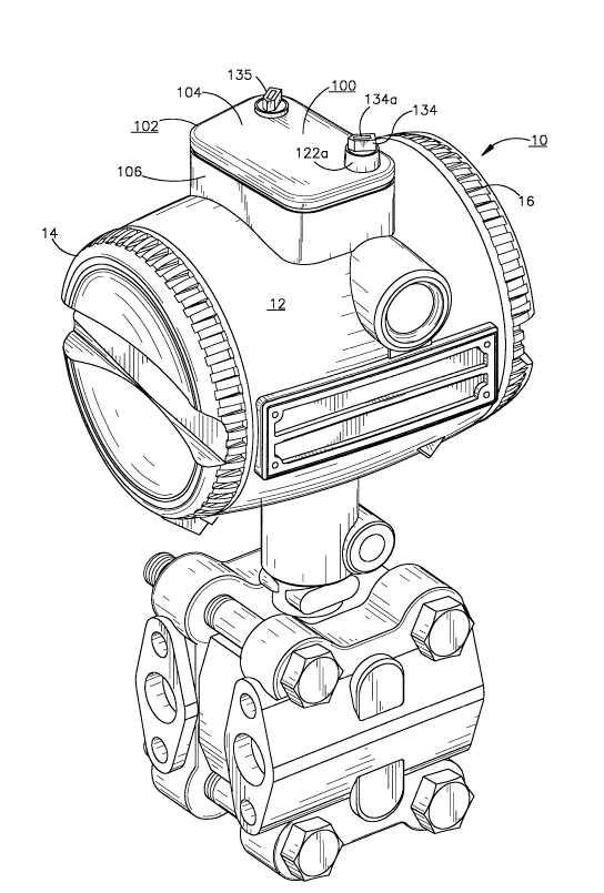
Fig. 1 shows a pressure transmitter 10 in conjunction
with the first embodiment 100 for the magnetic zero and span
actuator of the present invention. Transmitter 10 has a
main housing 12 which, as is shown in Fig. 1 of the 03280
PCT application, typically defines a pair of internal
chambers. The transmitter's energized electronics and
terminals are housed in the associated one of the two
chambers. The transmitter 10 includes threaded end caps 14
and 16 which screw into mating threads (not shown) on the
housing 12 to seal the chambers from the external
environment and provide explosion-proof characteristics to
the housing. An O-ring (not shown) may be associated with
end caps 14 and 16 to thereby provide a fluid-tight seal
with transmitter housing 12.
As is shown in the 03280 PCT application, a circuit
board which carries some of the energized transmitter
circuitry is usually positioned within one of the two
interior chambers of housing 12. The energized transmitter
terminals and a portion of the current loop circuit are also
usually located in the same chamber wherein the circuit
board is positioned.
Referring now to Fig. 2, there is shown the position
of the magnetically actuated zero and span reed switches 18
and 20 internal to housing 12. The reed switches are
usually located in the same chamber wherein the circuit
board is positioned. The reed switches 18 and 20 are
positioned in the chamber adjacent the inner surface 12a of
housing 12 so as to be located just below that portion of
outer surface 12b of housing 12 where the actuator 100 is
placed when it is desired to adjust the zero and span
settings of the transmitter. The reed switches may be
-
9 2100525
supported in their positions by appropriate means such as
the supports posts mounted to the circuit board shown and
described in the 03280 PCT application or may be soldered
directly to the circuit board.
Reed switches 18 and 20 are actuated by the single high
coercivity magnet 110 (see Figs. 2 and3) included in
actuator 100. The reed switches are normally open and do
not close until the centerline of the single magnet in
actuator 100 approaches the centerline of each of the reed
switches. A detailed description of the internal
construction and magnetic actuation of reed switches 18 and
20 is not needed herein as it is well known to those skilled
in the art and is given in the 03280 PCT application.
Referring now to Fig. 3, there is shown an exploded
perspective of the magnetic zero and span actuator 100 of
the present invention. Actuator 100 includes a housing 102
(see Fig. 1) which has a top cover 104 and a bottom cover
106. The top cover 104 is removable from bottom cover 106.
The inside bottom surface 106a of the bottom cover 106
includes a track 108 which is parallel to the front and rear
walls 106b and 106c of bottom cover 106.
Actuator 100 also includes a single high coercivity
magnet 110 which fits into an opening 112c (shown in Fig.
5) on the underside 112a of magnet carrier 112. Underside
112a also has a slot 112b which is complementary in shape
to track 108. Slot 112b allows magnet carrier 112 to slide
on track 108 between right and left side walls 106d and 106e
of bottom cover 106.
Actuator 100 further includes first and second
identical actuating arms 114 and 116 and the associated one
of first and second essentially identical return springs 118
and 120. The only difference between return springs 118 and
120 is that return spring 118 is right hand wound and return
spring 120 is left hand wound. Top cover 104 includes first
and second openings 122 and 124 which are associated with
a respective one of actuating arms 114 and 116. Since
,~
. "~ .
2100525
actuating arms 114 and 116 are identical and the return
springs 118 and 120 associated therewith are, except as
described above, identical only actuating arm 114 and its
associated return spring 118 need be described in detail.
Actuating arm 114 includes flat portion 126 which at
its right end has a cylindrical post 128 extending
downwardly from its bottom surface 126a of flat portion 126.
When actuator 100 is assembled, post 128 receives return
spring 118. Extending upwardly from the top surface 126b
of flat portion 126 at the same end that post 128 extends
downwardly from is post 130. Post 130 includes a first
essentially cylindrical portion 132 which has a groove 132a
for receiving an O ring (not shown). Extending upwardly
from cylindrical portion 132 is an essentially rectangular
portion 134 which has a slot 134a in its top surface for
receiving the complementary shaped tip of a tool such as a
screwdriver therein. When actuator 100 is assembled, the
rectangular portion 134 extends through opening 122 in top
cover 102 and the cylindrical portion 132 is seated therein
so that the o ring mounted in groove 132a provides a seal
for the opening 122.
At the left end of flat portion 126, an actuating pin
136 extends downwardly from surface 126a. Magnet carrier
112 includes first and second parallel slots 138 and 140
each associated with a respective one of the actuator pins
136 and 137 of actuator arms 114 and 116. Specifically,
slot 138 is associated with the actuating pin 136 and slot
140 is associated with the downwardly extending actuating
pin 137 of actuating arm 116. When actuator 100 is
assembled the actuating pins 136 and 137 engage the
associated one of slots 138 and 140. As will be described
in more detail hereinafter, the engagement of pin 136 with
slot 138 will cause magnet carrier 112 to move on track 108
towards the right side wall 106d when the tip of the tool
is inserted in slot 134a and the tool is given a
counterclockwise torque. Also as will be described in more
~.,
11 2100525
detail hereinafter, the engagement of pin 137 with slot 140
will cause magnet carrier 112 to move on track 108 towards
the left side wall 106e when the tip of the tool is inserted
in slot 135a and the tool is given a clockwise torque.
Referring now to Fig. 4a, there is shown a section
through actuator 100 with top cover 104 removed and the arms
114 and 116 in their null, i.e. unactuated positions. Slots
138 and 140 each contain a substantially double (or
opposing) wall section 138a and 140a and a substantially
single wall (or open) section 138b and 140b (see Fig. 3).
As will be described in more detail hereinafter, this
geometry of slots 138 and 140 allows the control of the
position of magnet carrier 112 to be passed or alternated
between actuating arms 114 and 116 while never allowing the
magnet carrier to be in a state of uncontrolled motion or
ambiguity. The geometry of slots 138 and 140 allows a
desirable separation of the zero and span reset functions
into two separate knobs and provides the actuator of the
present invention as distinct advantage as compared to the
prior art.
Referring now to Fig. 3a, there is shown an enlargement
of actuating pin 136 and slot 138. Pin 136 extends
downwardly from side 126a in a first tapered cylindrical
portion 136a. Thereafter pin 136 continues to extend
downwardly in a cylindrical portion 136b and terminates its
downward extension in a substantially spherical knob 136c
which engages the side walls 138e and 138d of slot 138.
As can be seen from Fig. 3a, the centerline 138c of
slot 138 is at an acute angle with respect to the centerline
136d of actuating pin 136. The reason therefor will be
described below.
Returning now to Fig. 3, it can be seen that spring 118
has first and second arms 118a and 118b. While not shown
in Fig. 3, bottom 126a of flat portion 126 has thereon
means, such as ribs 126c and 126d shown in phantom in Fig.
4a, to which spring arm 118a is clipped when spring 118 is
-
12 2100525
brought into assembled relationship with post 128. The
interior of bottom cover 106 includes cylindrical post 106f
(see Fig. 4a) which extends upwardly from the interior
bottom surface 106a and terminates in a smaller diameter
upwardly extending cylindrical post 106g. As is most
clearly shown in Fig. 4a, the interior of bottom cover 106
further includes along its right sidewall 106d an upwardly
extending shelf 106h and an upwardly extending rib 106i.
When actuator 100 is assembled, post 106g engages a
complementary opening (not shown) in the bottom of post 128
and, as is shown in Fig. 4a, arm 118b of spring 118 rests
on shelf 106h and against rib 106i.
The interior of bottom cover 106 also further includes
a upwardly projecting shelf and rib 106j and 106k (see Fig.
4a), which are associated with left sidewall 106e. When
actuator 100 is assembled and a counterclockwise torque is
applied to actuating arm 114, the magnet carrier 112 starts
to move to the right on track 108 since actuating pin 136
is in slot 138. Actuating arm 114 continues to move
counterclockwise in response to the torque applied to
actuating arm 114, and as is shown in Fig. 4b, edge 126e of
flat portion 126 comes into contact with rib 106i. The
contacting of edge 126e with rib 106i prevents further
rightward movement of the actuating arm 114, and therefore,
of magnet carrier 112 on track 108. Therefore, rib 106i
functions as a stop when arm 114 is actuated and in a
similar manner rib 106k functions as a stop when arm 116 is
actuated. It should be appreciated that the magnet carrier
has not contacted the associated side wall 106d or 106e when
either arm 114 or 116 comes into contact with the associated
stop 106i or 106k.
Bottom cover 106 also includes first and second arms
106m and 106n (see Fig. 4a) which project upwardly from
interior bottom surface 106a adjacent the interior of rear
wall 106c. As is shown most clearly in Fig. 4a, when
actuator 100 is assembled and the actuating arms 114 and 116
` A
,
-
13 2100S25
are in their null positions, a portion of the left edge 126f
of arm 114 rests against rear arm 106m and a portion of the
right edge of arm 116 rests against rear arm 106n.
Therefore, rear arms 106m and 106n function as stops for the
actuating arms 114 and 116 when the actuating arms are in
their null position. Arms 114 and 116 are held against
stops 106m and 106n by a preload torque on springs 118 and
120 at the assembly of actuator 100, until an actuation
torque is applied to either slot 134a or 135a (see Fig. 3).
Slidable magnet carrier 112 includes first and second
upwardly extending tabs 112d and 112e. As is shown in Fig.
5, when actuator 100 is assembled, tabs 112d and 112e
contact track 104a on the inside of cover 104 to help ensure
that carrier 112 follows track 108 and magnet 110 remains
essentially immobile in opening 112c when either of arms 114
and 116 are actuated.
Opening 122 of top cover 104 has an upwardly extending
sleeve 122a surrounding it. As is shown in Fig. 1, when
actuator 100 is assembled the rectangular portion 134 of
actuator arm 114 extends through opening 122. Sleeve 122a
surrounds rectangular portion 134 over a sufficient extent
of its length such that only a relatively small part of
portion 134 is accessible making it difficult to grasp
portion 134 by hand. Therefore, actuating arm 114 can only
be actuated by inserting the tip of a screwdriver blade in
slot 134a and applying a counterclockwise torque.
Opening 124 of top cover 104 does not have any upwardly
extending sleeve surrounding it. As is shown in Fig. 1,
when actuator 100 is assembled rectangular portion 135
extends through opening 124, and without any sleeve, portion
135 is accessible over essentially its entire length.
Therefore, actuating arm 116 can be actuated not only by
inserting the tip of a screwdriver blade into slot 135a but
also by grasping rectangular portion 135 and applying a
clockwise torque by hand.
" ï, ~
-
14 2100525
In actuator 100, actuating arm 114 is used to reset the
span of transmitter 10 while actuating arm 116 is used to
reset the zero of the transmitter. Therefore, sleeve 122a
ensures that the span of the transmitter can only be reset
by using a tool while the lack of an equivalent sleeve
surrounding opening 124 allows the zero of the transmitter
to be reset either by using a tool to apply the necessary
torque or applying that torque by hand.
The operation of actuator 100 will now be described in
connection with Figs. 4a and 4b. Referring first to Fig.
4a the actuator arms 114 and 116 are shown in their null
position. As was previously described, in the null position
arms 114 and 116 are held against stops 106m and 106n by a
preload torque on springs 118 and 120 at the assembly of
actuator 100, until an actuation torque is applied to either
slot 134a or 135a. Actuating pins 136 and 137 are stationed
in the single wall sections 138b and 140b of slots 138 and
140 when the actuator arms are in the null position.
The application of a counterclockwise torque to arm 114
causes the arm and therefore pin 136 to move in the
counterclockwise direction from the null position. During
this motion of arm 114, arm 116 is held in the null position
by the preload torque of spring 120. Continued
counterclockwise movement of the pin brings the pin 136 into
contact with side wall 138c of slot 138. At that point the
continued application of counterclockwise torque to
actuating arm 114 causes the magnet carrier to begin to move
to the right on track 108. Since the opening of the single
wall section 140b is greater than the diameter of pin 137,
the movement of the magnet carrier to the right is unimpeded
by pin 137.
In response to continued counterclockwise movement of
pin 136, magnet carrier 112 continues to move to the right
until edge 126e comes into contact with rib 106i. As is
shown in Fig. 4b, further movement to the right of magnet
carrier 112 is impeded by rib 106i. The centerline of
~`
-
210~525
magnet 110 is now essentially over the centerline of span
reed switch 18. Reed switch 18 closes and the closing of
the reed switch sets the span of transmitter 10. After the
span of the transmitter is set, the torque that was applied
to actuating arm 114 can be removed and the preload torque
on spring 118 causes the actuating arm to move clockwise and
the magnet carrier to move to the left. When the edge 126f
comes into contact with stop 106m the magnetic carrier and
the actuating arm have returned to the null position.
The zero of the transmitter can be set in a manner
similar to that described above for setting the span of the
transmitter. To set the zero, a clockwise torque is applied
to actuating arm 116 when actuating arms 114 and 116 are in
the null position. In response thereto, arm 116 and pin 137
moves in the clockwise direction until the pin comes into
contact with the left wall of slot 140. Continued clockwise
movement of pin 137 causes the magnet carrier 112 to move
to the left on track 108. Since the opening of the single
wall section 138b is greater than the diameter of pin 136,
the movement of the magnet carrier to the left is unimpeded
by pin 136.
The magnet carrier continues to move to the left in
response to a clockwise torque on actuating arm 116 until
the left edge of the flat portion of the actuating arm comes
into contact with rib 106k. The centerline of magnet 110
is then essentially over the centerline of zero reed switch
20. Reed switch 20 closes and the closing of the reed
switch sets the zero of transmitter 10. After the zero of
the transmitter is set, the torque that was applied to
actuating arm 116 can be removed and the preload torque on
spring 120 causes the actuating arm to move counterclockwise
and the magnet carrier to move to the right. When the right
edge of the flat portion of actuating arm 116 comes into
contact with stop 106n the magnetic carrier and the
actuating arm have returned to the null position.
: . .
-
16 2100525
A detailed description of how the zero or the span of
a transmitter is set when the zero or span reed switch
closes is not needed herein as it is well known to those
skilled in the art. Such a description is given in the
03280 PCT application.
Referring once again to Figs. 1 and 3, it is seen that
the actuator 100 sits on the exterior of transmitter housing
12 and is removable therefrom. The inside bottom surface
106a of bottom 106 is complementary in shape to the shape
of that portion of the transmitter housing upon which the
actuator sits. When it is desired to set either the zero
and/or the span of transmitter 10, the personnel trained to
perform those adjustments seat actuator 100 in place on the
exterior of the transmitter. After the zero andtor span
have been set, the actuator 100 is removed as a single unit
from the transmitter exterior thereby ensuring that the zero
and span settings of the transmitter cannot be tampered
with. It is not necessary to remove either the magnet 110
or the actuating arms 114 and 116 from the actuator in order
to ensure that the transmitter's zero and span settings will
not be tampered with. Additionally and in contrast to the
prior art, the removal of actuator 100 does not leave any
screw threads on the transmitter housing which may be
exposed to undesirable conditions.
Referring now to Fig. 6, there is shown an exploded
perspective for a second embodiment 200 for the actuator of
the present invention. The actuator 200 has a housing 202
with a bottom cover 204 and a top cover 206 which is
removably mounted on bottom cover 204. Top cover 206
includes a hinged dust cap 208 which is opened when it is
desired to adjust the zero and/or span reed switches 18 and
20.
Actuator 200 also includes a single high coercivity
magnet 210 which is mounted in an opening 212e of a magnet
carrier 212. Actuator 200 also includes a hub 213 which has
included as a part thereof a control knob 214. The control
17 2100525
knob and therefore the hub 213 is rotatable either in the
clockwise or counterclockwise directions. Magnet carrier
212 has a first rearwardly projecting arm 212a having an
opening 212b therein and a second rearwardly projecting arm
212c having an opening 212d therein. Arm 212c is parallel
to arm 212a. Hub 213 has drive pins 216, 218 (see Fig. 9)
and the openings 212b and 212d of the magnet carrier are
attached to the pins 216, 218 in a manner such that carrier
212 can be rotated only about the drive pins when control
knob 214 is rotated in the clockwise and counterclockwise
directions.
Control knob 214 includes slot 214a to receive the tip
of a screwdriver blade therein to thereby apply either a
clockwise or counterclockwise torque to the control knob.
As will be described in more detail below when actuator 200
is assembled a counterclockwise torque applied to the
control knob 214 will cause the hub 213 and therefore the
magnet carrier 212 to rotate soo in that direction so as to
be brought essentially over the centerline of zero reed
switch 18, as is shown in the simplified section of Fig. 12,
to thereby close that reed switch and reset the zero of the
transmitter. Also as will be described in more detail below
a clockwise torque applied to control knob 214 will,
provided span safety lock pushbutton 220 is depressed to
release a lock spring 236, cause the hub 213 and therefore
the magnet carrier 212 to rotate 90 in that direction so
as to be brought essentially over the centerline of span
reed switch 20 to thereby close that reed switch and reset
the span of the transmitter.
Actuator 200 further includes an O-ring 211 which seals
against an inside diameter 206a (see Fig. 8) in the roof 207
of top cover 206 to thereby provide a seal against water and
contaminants entering the actuator 200. The hub 213 has a
blind hole 213a (see Fig. 9) on axis in its bottom 213b
which fits over a raised stud 204b in the floor 205 of
bottom cover 204. Stud 204b establishes a rotation axis for
" ~
18 2 100525
the hub. The floor 205 of bottom cover 204 sustains axial
thrust placed on the hub 213 by the screwdriver inserted in
slot 214a.
Actuator 200 also further includes a return spring 226.
The spring 226 provides the torque to return the hub 213 and
therefore control knob 214 to the null position after the
knob is rotated either in the clockwise or counterclockwise
directions to adjust the reed switches. The spring 226 is
placed under a rotational preload as it is brought into
assembled relationship with hub 213. Hub 213 includes slots
213c and 213d.
Referring to Fig. 7, there is shown the spring 226 and
hub 213 in assembled relationship. As can be seen from a
comparison of Figs. 6 and 7 when spring 226 is brought into
assembled relationship with hub 213, the free end 226a of
the spring is placed in slot 213c and the free end 226b of
the spring is placed in slot 213d to maintain the rotational
preload. The portion 213e of hub 213 between slots 213c and
213d holds the free ends of the spring at a gap when the
control knob 214 and therefore the hub 213 and the magnet
carrier 212 are in the null, that is, unactuated, position.
As is shown in Fig. 8, the roof 207 of top cover 206
includes a rib 206b. When the actuator 200 is assembled and
in the null position the free ends 226a and 226b of spring
226 rest against an associated edge of the rib 206b.
As is shown in Fig. 6, hub 213 also includes stops 213f
and 213g. The roof 207 of top cover 206 (see Fig. 8)
includes another rib 206c. When the hub is rotated 90 in
the counterclockwise direction stop 213f comes into contact
with one edge of rib 206c. When the hub 213 is rotated 90
in the clockwise direction stop 213g comes into contact with
the other edge of rib 206c. It should be appreciated that
it is stops 213f and 213g of hub 213 and not the magnet
carrier 212 that comes into contact with the associated edge
of rib 206c to limit the travel of the magnet carrier to not
more than 90 in the clockwise and counterclockwise
2100525
19
directions. This interaction between stops 213f and 213g
of hub 213 and rib 206c prevents stress on magnet carrier
212 when the carrier is rotated soo in either direction from
the null position and thereby reduces the likelihood that
the magnet carrier will fail.
As is shown in Fig. 7, when the spring 226 and the hub
213 are in assembled relationship free ends 226a and 226b
of the spring project upwardly through slots 213c and 213d,
respectively. When the actuator 200 is assembled the free
ends of the spring come into contact with the edges of rib
206b. If control knob 214 is rotated in the
counterclockwise direction, free end 226a is kept from
moving by its associated edge of rib 206b and free end 226b
can move in 213d as it is not kept from moving by its
associated edge of rib 206b. This action spreads the spring
in one direction and provides the torque to return the
spring to the null position. If control knob 214 is rotated
in the clockwise direction, free end 226b is kept from
moving by its associated edge of rib 206b and free end 226a
can move in 213c as it is not kept from moving by its
associated edge of rib 206b. This action spreads the spring
in the opposite direction and provides the torque to return
the spring to the null position.
It is the spring 226, portion 213e of hub 213 and rib
206b which allow the control knob 214 and therefore the hub
213 and the magnet carrier 212 to rotate 90 degrees in
either direction from the null position and have a spring
return to an "off" position that is defined by a deadband
region of no spring force on the control knob 214. The
deadband region has a width which is no greater than the
width of portion 213e.
When the control knob 214 is in the null position the
magnet carrier 212 and therefore single high coercivity
magnet 210 is midway between reed switches 18 and 20. As
is shown in Fig. 6, actuator 200 includes magnetic shunts
210a and 210b mounted in appropriate receptacles therefor
A
~,,
2 100S25
in the floor 205 and the roof 207, respectively, to provide
a short circuit magnetic path for the magnetic flux from
magnet 210. When the control knob 214 is in the null
position the magnet 210 is positioned physically away from
the reed switches and between shunts 210a and 210b.
Therefore, shunts 210a and 210b together with a relative
separation between the reed switches and the magnet, prevent
magnet 210 from turning on the reed switches 18 and 20 when
the magnet carrier is in the null position.
Referring now to Fig. 8, there is shown first and
second curved guide tracks 222 and 224 in the roof 207 of
top cover 206. Guide track 222 is associated with reed
switch 18 and has a first end 222a adjacent the null
position of magnet carrier 212 and a second end 222b
adjacent the position of magnet carrier 212 when it is
rotated 90 in the counterclockwise direction. Guide track
224 is associated with reed switch 20 and has a first end
224a adjacent the null position of magnet carrier 212 and
a second end 224b adjacent the position of magnet carrier
212 when it is rotated 90 in the clockwise direction.
As can be seen in Fig. 8, guide track 222 increases in
thickness from end 222a to 222b and guide track 224
increases in thickness from end 224a to 224b. When control
knob 214 is rotated 90 in the counterclockwise direction
the magnet carrier 212 follows the curve of the floor 205
(see Fig. 6) of bottom cover 204 and the curve of guide
track 222 to bring the centerline of magnet 210 essentially
over the centerline of zero reed switch 18 (see the
simplified section of the actuator 200 shown in Fig. 12) to
thereby close that reed switch and reset the zero of the
transmitter. The increasing thickness of track 222 from end
222a to end 222b ensures that magnet 210 is close to reed
switch 18 when the magnet carrier has rotated 90
counterclockwise. When control knob 214 is rotated 90 in
the clockwise direction, provided span safety lock
pushbutton 220 is depressed to release lock spring 236, the
L.' - ' ,
21 2100525
magnet carrier follows the curve of the floor 205 and guide
track 224 to bring the centerline of magnet 210 essentially
over the centerline of span reed switch 20 to thereby close
that reed switch and reset the span of the transmitter. The
increasing thickness of track 224 from end 224a to end 224b
ensures that magnet 210 is close to reed switch 20 when the
magnet carrier has rotated 90 clockwise.
It should be appreciated that floor 205 and guide
tracks 222 and 224 form first and second curved paths to
direct the rotational motion of the magnet carrier 212 as
the control knob 214 is rotated in the clockwise or
counterclockwise directions. These curved paths allow the
magnet 210 to achieve both a close radial distance and
parallel orientation to the reed switches 18 and 20. The
close radial distance and the parallel orientation achieved
by the magnet 210 of actuator 200 substantially helps the
actuation of the reed switches by the magnet.
Referring once again to Fig. 6, it can be seen that the
span safety switch pushbutton 220 includes an O-ring seal
234 and has a self retaining tip 220a. Lock spring 236
includes a first straight portion 236a, first and second
ends 236b and 236c, second straight portion 236d and a
transition 236e between portions 236a and 236d. First
straight portion 236a has a slight upward slope from end
236b toward end 236c. Second straight portion 236d slopes
downwardly toward end 236c from essentially upwardly
extending transition portion 236e.
When actuator 200 is fully assembled the lower end
220a of pushbutton 220 is in contact with first straight
portion 236a of lock spring 236 near one end 236b of the
lock spring. As is shown in Fig. 11 when the actuator is
assembled end 236b is seated in an upwardly projecting
complementary shaped receptacle 204c in floor 205 and end
236c rests on the top of upward projecting ribs 204d in the
floor 205. It should be appreciated that the lock spring
does not rotate when the hub is rotated.
A
. f~
22 2100525
Referring once again to Fig. 7, it is seen that the
side of the hub 213 has a relatively thick portion 213h
which extends from the rightmost edge of stop 213f to about
the rightmost edge of portion 213e. At that point the side
undergoes an abrupt reduction in its thickness at edge 213j
to a relatively thin portion 213i which extends from about
the rightmost edge of portion 213e to the leftmost edge of
stop 213g.
When actuator 200 is assembled and is in the null
position the upward transition 236e of lock spring 236 is
just to the left of edge 213j. This location of the upward
transition of the lock spring relative to edge 213j in the
null position, except as described below, prevents rotation
of the hub in the clockwise direction unless the pushbutton
220 (see Fig. 6) is depressed to thereby push down the lock
spring. While not shown in Fig. 6, floor 205 includes an
upwardly circular post which is positioned to be just below
the point on lock spring 236a which is contacted by end 220a
of the pushbutton. The post limits the downward motion of
the lock spring when it is contacted by end 22Oa.
Referring now to Fig. 10, there is shown an enlargement
of the interface between lock spring edge 236e and
transition 213j of the hub edge. Lock spring 236 is
designed to provide a predetermined breakaway torque that
will allow edge 236e to slide by transition 213j in the hub
edge and thereby allow rotation of the hub in the clockwise
direction if an individual should try to rotate the hub in
that direction without first depressing pushbutton 220. The
predetermined breakaway torque is selected to avoid any
physical damage to the hub and the lock spring.
In designing the lock spring it was found that the
slight chamfer 236f in the transition shown in Fig. 10
helped to maintain the contact area between edge 236e and
the transition 213j even after repeated torquing of the hub
in the clockwise direction without depressing the pushbutton
220. Hub 213 may be fabricated from series 300 stainless
23 2100525
steel, lock spring 236 from 17-7 PH stainless steel heat
treated to RH950 per ASTM 693 and the chamfer may be in the
order of 25 on each edge.
In addition to the function described above, lock
spring 236 also affords some additional detent action to the
control knob 214 when it is in the null position. This
detent action in combination with O-ring 211, and shunts
210a, 210b provides resistance to the control knob to help
avoid undesirable vibration induced motion which might
otherwise accidentally actuate the reed switches.
Referring now to Figs. 6 and 13, the manner in which
the actuator 200 is mounted to the transmitter main housing
12 when it is desired to reset the zero and/or span reed
switches will now be described. The outside 203 of the
bottom cover 204 includes first and second identical means
240 for mounting the actuator 200 to the transmitter
housing. Only one of those means is shown in Fig. 13. In
addition and as is shown in Fig. 6 the actuator housing 202
includes a single hole 241 to receive screw 242.
The transmitter housing 12 includes first and second
actuator receiving means (not shown) which are complementary
in shape to the means 240. The actuator 200 is mounted on
housing 12 by first interfitting each of the two actuator
mounting means 240 with the associated one of the two
complementary actuator receiving means on the transmitter
and then tightening screw 242. When the actuator is mounted
on the transmitter housing, the portion 240a of the actuator
mounting means 240 shown in Fig. 13 rests on top of the
associated actuator receiving means to thereby provide
support for the actuator. As can be seen in Fig. 6, the
actuator housing 202 has sloped and low profile outside
surfaces which avoid the placement of side forces on the
actuator in the event someone climbing the installed
equipment uses the transmitter 10 as a step.
It is to be understood that the description of the
preferred embodiments are intended to be only illustrative,
`,' ~
24 210052~
rather than exhaustive, of the present invention. Those of
ordinary skill will be able to make certain additions,
deletions, and/or modifications to those embodiments of the
disclosed subject matter without departing from the spirit
of the invention or its scope, as defined by the appended
claims.
. ~