Note: Descriptions are shown in the official language in which they were submitted.
2100~29
Applicator Sleeve
The invention relates to a sleeve for use as an
outer sleeve and/or inner sleeve for a telescopic
applicator, consisting of a blank composed of a plane-
surface, rectangular length portion of a flexible,
cellulose-containing material, the two ends of the
blank being connected to one another to form a joining
seam extending in the longitudinal direction of the
sleeve, and the two longitudinal sides of the blank
forming the ends of the sleeve.
In sleeves of this generic type, it is known
that the joining seam is adhesively bonded in double
the thickness of the strip-shaped initial material,
such as, for example, cardboard, and leaves behind a
non-round inside diameter and a gaping joining seam on
the outer circumferential surface of the sleeve. Apart
from the fact that the appearance of this sleeve is
detrimental in view of the intended purpose mentioned
and can prompt psychological reservations as to use,
there is also the danger of irritation or injury to the
sensitive skin tissue when a sleeve of this type is
introduced into a body cavity.
It is known from US-4,522,967 to wind spirally
on itself a cardboard layer which is coated with a
heat-activatable adhesive. In this, after the first
winding, the cardboard strip is folded back on itself
and thereafter wound multiply on itself in the opposite
direction. The outer end of the coated cardboard strip
is located externally in a region situated in front of
the radial widening which the material experiences as a
result of the first backward folding of the strip at
the end of the first winding. This is intended to
~100.~29
ensure that the outer end of the coated cardboard strip
is inserted into the otherwise cylindrical
circumferential surface of the winding sleeve in front
of this thickened region. Nonetheless, the edge of the
outer end of the cardboard strip is exposed and forms a
groove-shaped depression in relation to the adjacent
strip material. The appearance of a sleeve of this type
is therefore not appreciably improved. Moreover, the
possibility of irritation or even injury to the skin
tissue by the exposed end edge also cannot be excluded
with certainty in this applicator sleeve.
The object on which the invention is based, is,
therefore, to improve a sleeve for use as an outer
sleeve and/or inner sleeve for a telescopic applicator,
especially for a tampon applicator for feminine
hygiene, in such a way that, whilst an economical
production of the sleeve is ensured, the danger of
irritation or iniury to skin tissue by the sleeve when
it is introduced into and when it is removed from the
body cavity is reliably prevented.
The invention achieves this object in that at
least fore-edges of the two interconnected ends of the
blank which are located on the outside of the sleeve
are arranged parallel and close against one another and
together are aligned with the bircumferential surface
of the tubular sleeve, so that the joining seam is
essentially smooth and invisible on the outside of the
sleeve.
Advantageously, at least parts of the two ends
of the blank are designed as bevelled cheeks, the faces
of which are directed parallel to one another and are
adhesively bonded with one another at a sticking point
of the sleeve.
According to the invention, a plurality of
embodiments of a sleeve can be developed from a blank
consisting of a basic layer and of an outer layer lying
above it, the outer layer and the basic layer forming a
unit. Thus, the basic layer and the outer layer can be
321~0~29
offset relative to one another in the longitudinal
direction of the blank such that the one end of the
blank is formed by the basic layer and the outer end of
the blank by the outer layer.
As the same time, according to one embodiment,
there can be provision for ensuring that the ends of
the outer layer and of the basic layer are respectively
connected to one another by butting flush against one
another, so that an outer joining seam of the outer
layer and an inner joining seam of the basic layer are
formed, with the result that the two joining seams
mentioned are offset relative to one another in the
circumferential direction of the sleeve.
In a further embodiment of the invention, it is
possible that only the ends of the outer layer be
connected to one another so as to butt flush against
one another and form an outer joining seam, whilst an
end portion of the basic layer overlaps its other end
and forms with this an inner joining seam which is
offset relative to the outer joining seam in the
circumferential direction of the sleeve. At the same
time, said end portion of the basic layer can be
provided with a fold, the other end of the basic layer
being located in front of the fold and forming with
this the inner joining seam.
In a further embodiment of this sleeve
according to the invention, for the production of which
is used a blank in which a basic layer and an outer
layer likewise form a unit, the basic layer and the
outer layer may be made equally long only at one end of
the blank, whilst at the other end of the blank the
basic layer is made longer than the outer layer. In
this case, only the ends of the basic layer are
designed as bevelled cheeks which, overlapping, are
adhesively bonded with one another, whilst the ends of
the outer layer are adhesively bonded with one another
so as to butt flush against one another.
Finally, it is also possible, in an embodiment
'
,
21~0~29
-- 4
of the sleeve according to the invention which uses a
blank produced as a unit from a basic layer and outer
layer, that the mutually opposite ends of the basic
layer and outer layer of the blank have an equal length
and are designed as bevelled cheeks which are directed
parallel to one another.
The sleeve according to the invention is
especially suitable as an inner sleeve and~or outer
sleeve for applicators for the introduction of tampons
for feminine hygiene.
It is recommended to use as a material for the
blank, sulfate cellulose cardboard which, should the
sleeve be used for a tampon applicator for feminine
hygiene, advantageously has a weight of 260 g/m2 and a
thickness of 350 ~m. Furthermore, the sulfate cellulose
cardboard can be laminated with calcium carbonate and,
if appropriate, additionally calendered in a glazing
calender. Moreover, a material having as an outer layer
varnished paper or a thin plastic foil can also be used
for the sleeve blank.
The invention is explained in more detail below
by means of the diagrammatic drawing of a plurality of
exemplary embodiments. In the drawing:
Figure 1 shows a partially cutaway, perspective
view of a blank composed of a rectangular cardboard
portion for a first embodiment of a sleeve according to
the invention;
Figure 2 shows a view of the blank according to
Figure 1, but in which the fore-faces of the two ends
of the blank are bevelled to form cheeks;
Figure 3 shows the first embodiment of the
sleeve according to the invention, in which the cheeks
are connected to one another to form a joining seam;
Figure 4 shows a perspective view of a
longitudinally extending, strip-shaped blank for a
second embodiment of a sleeve according to the
invention, an outer layer being offset relative to a
basic layer in the longitudinal direction of the blank;
21Q0~29
-- 5 --
Figure 5 shows a partially cutaway, perspective
view of the second embodiment of the sleeve which is
produced from the blank according to Figure 4;
Figure 6 shows a partially cutaway, perspective
front and top view of a third embodiment of the sleeve
composed of a blank similar to that according to
Figure l;
Figure 7 shows a partially cutaway, perspective
representation of a strip-shaped blank having a basic
layer and an outer layer for a fourth embodiment of a
sleeve according to the invention;
Figure 8 shows the blank according to Figure 7
with parallel cheeks of the basic layer which are
bevelled at equal angles;
15 Figure 9 shows a partially cutaway, perspective
view of the fourth embodiment of a sleeve according to
the invention produced from the blank according to
Figure 8;
Figure 10 shows a cutaway, perspective
representation of a blank having a basic layer and an
outer layer for a fifth embodiment of the sleeve
according to the invention;
Figure 11 shows the blank according to
Figure 10 with fore-ends of the basic layer and outer
i 25 layer of the blank which are bevelled at equal angles;
and
Figure 12 shows a cutaway, perspective view of
a fifth embodiment of the sleeve according to the
invention produced from the blank according to
Figure 11.
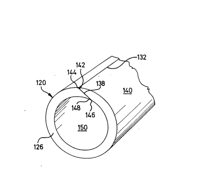
Figure 3 shows a first embodiment of a sleeve
120 for use as an outer sleeve andtor inner sleeve for
a telescopic tampon applicator for feminine hygiene.
Applicators of this type consist of two sleeves
displaceable one in the other, the inner sleeve serving
for pushing the tampon out of the outer sleeve.
Furthermore, applicators produced with the sleeve
according to the invention are also suitable for
- : ' . . . : ~ . . . -
... . . - ~. . . -
. .
:
.': . .' ' .' ' ~
::
2100529
introducing hygienic and/or medical articles or
substances into other body cavities of humans or
animals. Applicators of the type mentioned are
generally known, and therefore there is no need for a
complete representation of them in the drawing.
According to Figure 1, the sleeve 120 consists
of a blank 122 composed of a plane-surface, rectangular
length portion of a plane-surface, flexible, cellulose-
containing material having a topside 121 and an
underside 123 parallel to this.
Figure 1 shows a longitudinal edge 124 of the
blank 122, the length of which corresponds
approximately to the circumferential length of the
finished sleeve 120 and which forms an open fore-end
15 126 of the sleeve 120 in Figure 3. The longitudinal
edge of the blank 122, located opposite and parallel to
and at a distance from the longitudinal edge 124 and
made of equal length, is not shown because of the
cutaway representation of the blank 122 in Figures 1
20 and 2 and of the sleeve 120 in Figure 3. Two mutually
parallel ends 128, 130 limiting the length of the blank
122 extend at right angles to the longitudinal edge 124
of the blank 122.
As shown in Figure 2, the fore-faces of the
25 ends 128, 130 of the blank 122 are bevelled, so that
they form cheeks 134, 136 which are directed parallel
to one another. The angles ~ of the two cheeks 134, 136
thus correspond to one another, so that, irrespective
of the size of the bevel angle, the sleeve 120
preserves the normal thickness of the blank 122 in the
region of a joining seam 132. Since the bonding surface
made available for the joining seam 132 by the cheeks
134, 136 becomes larger, the smaller the bevel angle
selected, the endeavour will be to select the bevel
35 angle of the cheeks 134, 136 as small as possible.
Angles of less than 30 are therefore to be preferred.
Consequently, the cheeks 134, 136 make in parallel with
one another when, according to Figure 3, they are
- -.' ' .~ :
''' ~, : ' : :
- : ~ .
2100~29
adhesively bonded with one another at a sticking point
138 to form the joining seam 132.
An outer fore-edge 142 and an outer fore-edge
144 of the interconnected ends 128, 130 of the blank
122, which is formed by the two cheeks 134, 136, are
arranged parallel and close against one another and
together are aligned with an outer circumferential
surface 140 of the sleeve 120, so that the joining seam
132 is smooth and virtually invisible on the outside of
the sleeve 120.
Correspondingly, an inner fore-edge 146 of one
cheek 134 and an inner fore-edge 148 of the other cheek
136 lie so close together in an inner, approximately
cylindrical circumferential surface 150 of the sleeve
120 that, there too, a smooth wall is present. Because
of the outer and inner, smooth essentially cylindrical
circumferential surfaces 140, 150 of the sleeve 120,
not only does the latter have a good appearance, but
skin irritations or inflammations when the sleeve is
introduced into and removed from the body cavity are
prevented and an extremely careful handling of an
article, such as, for example, a tampon or suppository,
arranged in the sleeve is ensured.
Figure 4 illustrates a blank 222 for a second
embodiment of the sleeve 220 in Figure 5. The blank
222, likewise consisting of a plane-surface and
rectangular material portion, is composed of a basic
layer 224 and of an outer layer 226 which lies above it
and which is firmly connected to the basic layer as a
unit. Whilst the basic layer 224 and the outer layer
226 are made of equal width so that their longitudinal
edges 228, 230 are flush with one another, the outer
layer 226 is offset relative to the basic layer 224 in
the longitudinal direction of the blank 222, as shown
35 in Figure 4. Consequently, one end 232 of the blank 222
is formed by an end portion 238 of the basic layer 224
which projects beyond an adjacent end 240 of the outer
layer 226. Another end 234 of the blank 222 is formed
. , .
2100~29
-- 8 --
by an end portion 244 of the outer layer 226 which
projects beyond an adjacent end 242 of the basic
layer 224.
Because the basic layer 224 and the outer layer
226 are offset relative to one another in the
longitudinal direction, the end portion 238 of the
basic layer 224 and one end portion 244 of the outer
layer 226 overlap when a sleeve 220 is formed. As a
result, the fore-faces, perpendicular to the main plane
of the blank 222 or extending radially relative to the
core of the sleeve 220, of the ends 234, 240 of the
outer layer 226 lie closely and flush against one
another and are connected to one another by means of a
sticking point 246, so that a joining seam 236 is
formed (Figure 5). At the same time, outer, opposite
fore-edges 256, 258 of said ends 234, 240 of the outer
layer 226 are aligned with an outer circumferential
surface 248 of the sleeve 220 and form the smooth,
virtually invisible joining seam 236, as shown in
Figure 5. In order to obtain the closed joining seam
236 as a result of a mutual contact of the vertical
fore-faces of the ends 234, 240 of the outer layer 226
of the sleeve 220, it is recommended to make the end
portion 238 of the basic layer 224 slightly shorter
! 25 than the end portion 244 of the outer layer 226.
The fore-edges 260, 262 of the two ends 232,
242 of the basic layer 224 are likewise connected to
one another by means of a sticking point 250 and form
an inner, closed, smooth joining seam 252 which is
aligned with an inner, smooth, circumferential surface
254 of the sleeve 220. This sleeve 220 is therefore
suitable, like the sleeve of the above-described first
embodiment, for receiving a tampon.
Figure 6 shows a third embodiment of the sleeve
320 which can be produced from a blank which is not
illustrated, but is similar to that shown in Figure 4.
In contrast to the second embodiment, according to
Figure 6 one end portion 338 of a basic layer 324 is
2100~29
g
prefolded radially inwards the amount of the thickness
of the basic layer 324 by means of a fold 328. This end
portion 338, which has an end 332, therefore overlaps
an opposite end 342 of the basic layer 324 and is
connected to this by adhesive bonding. The end 342 of
the basic layer 324 is located close in front of the
fold 328 and forms with the fold 328 an inner joining
seam 346.
An outer layer 326 of the sleeve 320 covers the
inner joining seam 346 of the basic layer 324. The
outer layer 326 projects beyond the end 342 of the
basic layer 324 in the circumferential direction of the
sleeve 320 by means of an end portion 344 so far that
the two opposite ends 334, 340 of the outer layer 326
butt against one another offset relative to the joining
seam 346 of the basic layer 324 in the circumferential
direction of the sleeve 320 and are adhesively bonded
with one another. Outer fore-edges 356, 358 of the ends
334, 340 of the outer layer 326 lie close against one
another in the outer, essentially cylindrical
circumferential surface of the sleeve 320 and form an
outer, smooth joining seam 336 virtually invisible to
the eye.
According to Figure 7, in a blank 442 for a
fourth embodiment of the sleeve 420 in Figure 9,
vertical fore-faces of one end 432 of a basic layer 424
and of one end 440 of an outer layer 426 lie flush one
above the other. In contrast, an end portion 452 of the
basic layer 424, which has an end 442, projects in the
longitudinal direction beyond another end 434 of the
outer layer 426. By deformation or machining, for
example by grinding or rolling, transversely to the
longitudinal direction of the blank 422 in the
direction of the arrow x in Figure 8, the projecting
end portion 452 of the basic layer 424 is bevelled on
the top side facing the outer layer 426 as far as the
end 434 of the outer layer 426 and forms a cheek 454.
The cheek 454 has a projecting fore-edge 446 which lies
'
2~0D~29
-- 10 --
in the plane of the underside 456 of the basic layer
424 or of an innér circumferential surface of the
sleeve 420. The bevelled cheek 454 projecting beyond
the outer layer 426 forms an angle ~ with the underside
456 of the basic layer 424 and, at its upper or outer
end, terminates at a lower end edge 428 of the vertical
fore-face of the end 434 of the outer layer 426.
As shown in Figure 8, the end 432 of the basic
layer 424 is likewise bevelled by grinding or rolling,
so that a cheek 458 corresponding to the cheek 454 is
also present at the one end 432 of the basic layer 424,
the faces of the cheeks 454, 458 extending parallel to
one another. The cheek 458 therefore forms with the
underside of the outer layer 426 an angle ~, the vertex
of which is located at the lower edge of the end 440 of
the outer layer 426.
When the blank 442 according to Figure 8 is
wound round a winding mandrel 460 in Figure 9 in order
to produce a sleeve 420, the cheek 458 at one end of
20 the basic layer 424 overlaps the cheek 454 at the other
end of the basic layer 424 and is connected to this at
a sticking point 438 to form an inner, closed joining
seam 444 which lies in the inner circumferential
surface of the sleeve 420 and which is made smooth with
25 this. The ends 434, 440 of the outer layer 426 have
outer fore-edges 448, 450 which extend approximately
radially relative to the longitudinal mid-axis of the
winding mandrel 460, so that, lying close against one
another, they form an outer joining seam 436 which
closes off the outer surface of the sleeve 420 in a
smooth-walled manner. Here too, therefore, the wall
thickness of the sleeve 420 corresponds in the region
of the joining seams 436, 444 to the thickness of the
blank 422.
Figure 12 illustrates a fifth embodiment of a
sleeve 520 which consists of a rectangular, flat blank
522 in Figure 11, composed of a basic layer 524 and of
an outer layer 526 which lie congruently one above the
2100~29
-- 11 --
other and which form a fixed unit (Figure 10).
According to Figure 11, in this case not only
opposite ends 532, 542 of the basic layer 524, but also
opposite ends 534, 540 of the outer layer 526 are
respectively bevelled at an equal angle ~ relative to
the topside and underside of the blank 522 by grinding
or rolling, so that their angled faces are directed
parallel to one another and form respective cheeks 554
and 558. The vertex of the angle ~ of the cheek 554
coincides with a lower fore-edge 544 of the other fore-
end 542 of the basic layer 524. In contrast, the vertex
of the angle ~ of the cheek 558 is located in an upper
fore-edge 530 of the fore-end 540 of the outer layer
526. When the bevelled, parallel cheeks 554, 558 are
adhesively bonded with one another at a sticking point
539, in this fifth embodiment of the sleeve 520, too,
the wall thickness of the latter at the sticking point
539 corresponds to the wall thickness of the sleeve
wall or the blank 522. At the same time, outer fore-
edges 528, 530 of the cheeks 554, 558 once again lie
closely flush against one another in the outer
circumferential surface of the sleeve 520, so that a
smooth joining seam 536 which is virtually invisible is
obtained on the circumferential surface of the sleeve.
In the present exemplary embodiment, however,
inner fore-edges 544, 546 of the cheeks 554, 558 also
lie close to one another in the inner, essentially
cylindrical circumferential surface of the sleeve 520.
Consequently, the single, inwardly continuous joining
seam 536 is formed by said bevelled cheeks 554, 558
(Figure 12) when the blank 522 is wrapped round a
winding mandrel 560 and the cheeks 554, 558 are
overlapped and adhesively bonded, as described. As the
joining seam 536 lies both internally and externally in
the inner and outer circumferential surface of the
sleeve 520 respectively, this sleeve 520 is also
suitable especially as an outer sleeve for a tampon
applicator for feminine hygiene.
2100~29
- 12 -
A sulfate cellulose cardboard in particular is
suitable as a basic material for producing the above-
described sleeves. If the sleeves are used for tampon
applicators for feminine hygiene, it is recommended to
use a sulfate cellulose cardboard of a weight of
approximately 260 g/m2 and of a thickness of
approximately ~50 ~m. Unevenesses of the material can
be laminated with calcium carbonate. Furthermore, a
glossy appearance can be imparted to the surface of the
material by means of a glazing calender. The above~
described first embodiment of the sleeve 120 can be
! produced completely from the material mentioned. It
dissolves easily in water and, if appropriate, is also
reusable. It is also possible to use sulfate cellulose
cardboard for the four last-mentioned embodiments of
the sleeve according to the invention. In these cases,
the outer layer of the sleeve can also consist of other
materials, such as, for example, a foil composed of a
preferably biologically degradable plastic, varnished
paper or the like. The blank can consist not only
partially, but also completely of biologically
degradable plastic.
For the adhesive bonding of the ends of the
blank to form the sleeve, conventional, hot-melt
adhesives, which are generally known to an average
person skilled in the art and which are therefore not
listed in detail, are preferred.
2100~29
- 13 -
List of Reference Symbols
120 Sleeve
121 Top side
5 122 Blank
123 Underside
124 Longitudinal edge
126 Open fore-end
128,130 Ends of the blank
132 Joining seam
134,136 Cheeks
138 Sticking point
140 Outer circumferential surface
142,144 Outer fore-edges
146,148 Inner fore-edges
150 Inner circumferential surface
220 Sleeve
222 Blank
224 Basic layer
20 226 Outer layer
228 Longitudinal edge
230 Longitudinal edge
232 End -
234 End
25 236 Joining seam
238 End portion
240 End
242 End
244 End portion
30 246 Sticking point
248 Outer circumferential surface
250 Sticking point
252 Inner joining seam
254 Inner circumferential surface
256,258 Outer fore-edges
260,262 Fore-edges
320 Sleeve
322
- 14 210 0~ 29
324 Basic layer
326 Outer layer
328 Fold
330
5 332 End
334 End of outer layer
336 Joining seam of outer layer
338 End portion
340 End of outer layer
10 342 End of basic layer
344 End portion
346 Inner joining seam
348
350
352
354
356 Fore-edge
358 Fore-edge
420 Sleeve
422 Blank
424 Basic layer
426 Outer layer
428 Lower end edge ,~
430
j 25 432 End
434 End of outer layer
436 Joining seam
438 Sticking point
439 Inner joining seam
30 440 End of outer layer
442 End
444 Inner joining seam
446 Fore-edge
448 Outer fore-edge
35 450 Outer f ore-edge
452 Basic layer
454 Cheek . -
456 Underside
2100~29
- 15 -
458 Cheek
460 Winding mandrel
520 Sleeve
522 Blank
5 524 Basic layer
526 Outer layer
528
530 Upper fore-edqe
532 End of basic layer
10 534 End of outer layer
536 Joining seam
538
539 Sticking point
540 End of outer layer
15 542 End of basic layer
544 Lower fore-edge
546 Inner fore-edge
548
550
552
554 Cheek
556
558 Cheek
560 Winding mandrel