Language selection

Search

Patent 2100632 Summary

Third-party information liability

Some of the information on this Web page has been provided by external sources. The Government of Canada is not responsible for the accuracy, reliability or currency of the information supplied by external sources. Users wishing to rely upon this information should consult directly with the source of the information. Content provided by external sources is not subject to official languages, privacy and accessibility requirements.

Claims and Abstract availability

Any discrepancies in the text and image of the Claims and Abstract are due to differing posting times. Text of the Claims and Abstract are posted:

  • At the time the application is open to public inspection;
  • At the time of issue of the patent (grant).
(12) Patent: (11) CA 2100632
(54) English Title: POSITIVE RAKE INSERT HAVING SERRATIONS FOR CUTTING
(54) French Title: PLAQUETTE D'USINAGE RAPPORTEE A PENTE POSITIVE ET STRIES
Status: Expired and beyond the Period of Reversal
Bibliographic Data
(51) International Patent Classification (IPC):
  • B23C 05/04 (2006.01)
  • B23C 05/20 (2006.01)
(72) Inventors :
  • ALLAIRE, PAUL (United States of America)
(73) Owners :
  • VALENITE INC.
(71) Applicants :
  • VALENITE INC. (United States of America)
(74) Agent: R. WILLIAM WRAY & ASSOCIATES
(74) Associate agent:
(45) Issued: 1998-07-07
(22) Filed Date: 1993-07-15
(41) Open to Public Inspection: 1994-02-04
Examination requested: 1996-03-20
Availability of licence: N/A
Dedicated to the Public: N/A
(25) Language of filing: English

Patent Cooperation Treaty (PCT): No

(30) Application Priority Data:
Application No. Country/Territory Date
07/923,650 (United States of America) 1992-08-03

Abstracts

English Abstract


A polygonal, indexable cutting insert having a positive rake
and a cutting edge having a truncated sinusoidal form.


French Abstract

La présente invention vise une pastille de découpage indexable polygonale présentant un angle de coupe positif et un tranchant de forme sinusoïdale tronquée.

Claims

Note: Claims are shown in the official language in which they were submitted.

CLAIMS
I Claims:
1. A polygonal, indexable cutting insert having a positive
rake, comprising;
a top surface and bottom surface substantially parallel
to each other and separated by a sidewall running substantially
unbroken therebetween to define a body, said sidewall comprised of
a plurality of side flank surfaces which are substantially planar,
each side flank surface extending from corner to corner of the
insert body, each side flank intersects the bottom surface along
its entire edge at an obtuse angle and the top surface along its
edge at an acute angle so that the insert has a positive rake
profile; said intersection of each side flank and the top surface
forms a cutting edge; each said cutting edge has a plurality of
equally spaced serrations having their center lines spaced a part
from each other; each serration being perpendicular to the top
surface and intersecting the side flank intermediate the width of
said side flank.
2. The insert of claim 1, wherein said serrations are
sinusoidal in shape.
3. The insert of claim 1, further including a centrally
located aperture in the top surface and extending through the body
of the insert, said aperture further equipped with a counterbore
at the top surface.
- 7 -

4. The insert of claim 2, wherein said sinusoidal serrations
are truncated below the mean line of the sinusoidal curve.
5. The insert of claim 1, wherein the insert is shaped as
a regular polygonal.
6. The insert of claim 1, wherein the positive rake of each
side flank is approximately 11°.
7. The insert of claim 1, wherein each corner is chamfer at
approximately 45° to 90°
8. In a cutting tool having a plurality of insert pockets,
each pocket having a seating surface and sidewalls, and means to
retain the insert in the pockets, a plurality of polygonal inserts
having a top surface and a bottom surface substantially parallel
to each other, said bottom surface adapted to seat on the seating
surface of the tool pocket, said top and bottom surface having a
sidewall extending substantially unbroken therebetween to define
a body, said sidewall comprised of a plurality of side flank
surfaces which are substantially planar, each side flank surface
extending from corner to corner of the insert body, each corner
being chamfered, each side flank intersects the bottom surface
along its entire edge at an obtuse angle and the top surface along
its entire edge at an acute angle so that the insert has a positive
rake profile; said intersection of each side flank said top surface
forms a cutting edge; each cutting edge having a plurality of
equally spaced, truncated serrations having their center liens
spaced from each other; each serration being perpendicular to the
- 8 -

top surface and intersecting the side flank intermediate the width
of said side flank; each said insert arranged in the cutting tool
in helical rows and each row is spaced apart from each other
according to the formula
Z = Y/2 - (S); wherein
Z is the chamfer of the insert;
Y is the serration below the mean line of the curve
S is the distance between inserts in the cutter
body.
9. The cutting tool of claim 8, wherein each corner of the
insert is chamfered at an angle between about 45° to 90°.
10. The cutting tool of claim 8, wherein the positive rake
of each side flank is about 11°.
11. The cutting tool of claim 8, wherein the insert further
includes a centrally located aperture in the top surface and
extending through the body of the insert, said aperture further
equipped with a counterbore at the top surface.
- 9 -

Description

Note: Descriptions are shown in the official language in which they were submitted.


-'- 2~6~
P08ITIY~ RA~E ~ hl
HA~ING 8B~RATION8 FOR ~u~.lNG
B~C~GROUND OF T~E l~v~h.ION
1. Field of the inventio~.
The present invention relates to a polygonal lay down
indexable insert for cutting metals which has a positive rake and
a truncated sinusoidal form along the cutting edge of the insert.
The present invention further relates to a ,polygonal form
indexable cutting insert having a positive rake, and a truncated
sinusoidal form along the cutting edge which intersects the top
surface of the insert at a right angle and intersect the flanks of
the insert at some point intermediate between the top and bottom
surfaces and which insert is capable of being formed by a
conventional pressing methods.
2. Description of the Related Art
Malinchak, U.S. Patent No. 3,875~Ç31 discloses a negative rake
insert having sinusoidal serrations along the entire width of the
cutting edge and flanks of the insert. Being a negative rake
insert, the insert provides for eight faces which may be used in
cutting operations. It is contemplated that the ~alinchak insert
~ay be used in concert with other inserts o~ like design such that
the insert6 are staggered according to a ~ormula and presented to
a metal piece f or cutting.

fi 3 2
Malinchak, U.S. Patent No. 3,922,766 discloses a cutting tool
having a plurality of inserts. EAch insert is in the form of a
circular disk or cylinder having a plurality of cutting teeth
disposed symmetrically around the outer periphery. The cutting
members are adjusted in the holder so that each tooth progressively
cuts behind the tooth ahead of it so that the peaks of one edge
cover a part of the trough of another edge whereby cutters
progressively cut an article. The cutters can be adjusted so that
as certain teeth wear, that the cutters can be rotated to bring
additional new teeth into cutting position.
8UMMARY OF ~HE lNv~h~loN
The present invention is a polygonal indexable insert having
a positive rake. The insert comprises a top and ~ottom surface
which are substantially parallel to each other and separated by a
sidewall running substantially unbroken therebetween to define a
body~ The sidewall is comprised of a plurality of side flank
surfaces which are substantiallv planar in shape. Each side flank
surface extends from corner to corner of the insert. Each side
flank surface intersects-the bottom surface along its edge at an
obtuse angle and intersects the top surface along its edge at an
acute angle so that the insert may be seen to have a positive rake
profile along each side flank. The intersection of each side flank
at the top surface forms a cutting edge. Each cutting edge has a
plurality of equally spaced serrations formed in each side of the
insert and having their center lines spaced apart from each other.

h ~ 3 2
Each serration is perpendicular at the top surface and intersects
the side flank at a point intermediate the width of the side flank
face. It is contemplated that the side flanks extend outwardly
from the bottom surface toward the top at approximately 11-.
The serrations are preferably sinusoidal in shape and are
truncated at each crest of the sinusoidal curve below the mean line
of the curve. ~lthough the insert may be any polygonal shape, it
is preferred that the insert is a regular shaped polygon and each
cutting edge is identical to the others. A centra~l aperture may
be provided to secure the insert in place.
BRIEF DESCRIP~ION OF ~ DRA~INGS
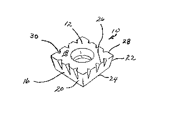
Figure 1 is a perspective top view of the insert of the
present invention.
Figure 2 is a top plan view of the insert showing a
configuration of the cutting edges.
Figure 3 is a cutaway view of the insert along lines 3 as
taken in Figure 2, showing the orientation of the sinusoidal curves
in the side flanks of the insert.
Figure 4 is a detailed view of the cutting edge of Figure 2
showing the truncated sinusoidal configuration of the cutting
insert.
DETAI~ED DESCR:CPTION OF 'r~13 PREF13RRED EIIBODIME~Nl!
Turning now to the drawings, wherein like numerals reference
like structures, insert 10 is comprised of a top surface 12, a
bottom surface 14, and a sidewall 16 extending substantially

unbroken therebetween to define a body 18. The insert is polygonal
in shape and is preferably a regular polygon. Each sidewall is
comprised of a side flank 20 which extends from corner to corner,
each designated as 22. Each side flank intersects the bottom
sur~ace at edge 24 and the top surface at edge 26. It should be
noted that the present invention relates to a positive rake insert.
Accordingly, the components side flanks intersect the bottom edge
at an obtuse angle and intersect the top edge at some abute angle.
The intersection of each side flank and the top surface forms the
cutting edge 28. Each cutting edge has a plurality of equally
spaced, preferably sinusoidal shaped serrations formed in each
cutting edge of the insert. The center lines of the sinusoidal
curves are spaced apart from each other. Each serration is
situated along the cutting edge and intersects the top surface
perpendicular to the surface itself and intersects the side ~lank
at some point intermediate the top a~d bottom surfaces. Turning
now to Figures 1 and 4, it can be seen that serrations 30 are
flattened at the crest of the curve whereas the roots of the curve
are intact. Thus, it can be seen that the sinusoidal curve is
truncated. By this term, it is meant that the crest of the curve
is ~lattened. Preferably, the curve is truncated below the mean
line o~ the sinu~oidal curve.
It is further understood that the insert described herein is
used in plurality in a cutting tool. Specifically, the inserts are
arranged in rows in insert pockets. Each pocket has seating

~0~3~
surface and side walls and the insert is fastened thereto. The
next row is arranged in tool pockets so that the relationship
between each row of inserts is best seen using the formula
Z = Y
S is the distance between inserts in the cutting tool body;
Z is the chamfer of the insert;
Y is the width of the serration below the mean line of the
sinusoidal curve. It is further preferred that the inserts are
arranged in helical rows is in the direction of cutting.
Turning now to Figure 4, the width of the serration portion
~yll is seen to differ from the width of truncated portion X. Thus,
it can be seen that by truncating the sinusoidal curve below the
mean line, X > Y. Similarly Z, which is the chamfer of the insert,
is .008" to .01" less than 1/2 the Y dimension so that when the
inserts are positioned in a cutter tool body, the X dimension of
an insert in an adjacent flute or row will overlap and cover the
spaca between adjacent inserts in the next row according to the
~ormula
2 Z ~ .015/.020 = Y
The positive rake insert of the present invention may further
be equipped with a central aperture to facilitate holding the
insert in a tool pocket holder.
Turning now to Figures 2 and 3. Figure 2 is a top plan view
of the insert. Note the central aperture 34 with counter bore 36

~r
2 1 ~ i 3
for fastening the insert into an insert pocket of a tool. Note
~hat each edge 28 is identical. However, those skilled in the art
recognize that the insert may be any polygonal shape and the sides
need not be identical.
Figure 3 is taken alo~g lines 3-~ of Figure 2 and shows a
cross section of the insert indicating the manner in which the
truncated sine curve serration intersects the top surface at 90 ,
as shown by line 30, and the side flank at some point along the
width of the side flank intermediate the top and bo,ttom edge.
Those skilled in the art will recognize that the invention
described herein is capable of many modifications and variations
without departing from the scope and spirit of the invention.

Representative Drawing
A single figure which represents the drawing illustrating the invention.
Administrative Status

2024-08-01:As part of the Next Generation Patents (NGP) transition, the Canadian Patents Database (CPD) now contains a more detailed Event History, which replicates the Event Log of our new back-office solution.

Please note that "Inactive:" events refers to events no longer in use in our new back-office solution.

For a clearer understanding of the status of the application/patent presented on this page, the site Disclaimer , as well as the definitions for Patent , Event History , Maintenance Fee  and Payment History  should be consulted.

Event History

Description Date
Time Limit for Reversal Expired 2006-07-17
Inactive: IPC from MCD 2006-03-11
Letter Sent 2005-07-15
Grant by Issuance 1998-07-07
Pre-grant 1998-03-23
Inactive: Final fee received 1998-03-23
Notice of Allowance is Issued 1997-10-21
Letter Sent 1997-10-21
Notice of Allowance is Issued 1997-10-21
Inactive: Status info is complete as of Log entry date 1997-10-15
Inactive: Application prosecuted on TS as of Log entry date 1997-10-15
Inactive: Approved for allowance (AFA) 1997-08-12
Classification Modified 1997-08-12
Inactive: IPC removed 1997-08-12
Inactive: First IPC assigned 1997-08-12
Inactive: IPC assigned 1997-08-12
All Requirements for Examination Determined Compliant 1996-03-20
Request for Examination Requirements Determined Compliant 1996-03-20
Application Published (Open to Public Inspection) 1994-02-04

Abandonment History

There is no abandonment history.

Maintenance Fee

The last payment was received on 1997-06-30

Note : If the full payment has not been received on or before the date indicated, a further fee may be required which may be one of the following

  • the reinstatement fee;
  • the late payment fee; or
  • additional fee to reverse deemed expiry.

Patent fees are adjusted on the 1st of January every year. The amounts above are the current amounts if received by December 31 of the current year.
Please refer to the CIPO Patent Fees web page to see all current fee amounts.

Fee History

Fee Type Anniversary Year Due Date Paid Date
MF (application, 4th anniv.) - standard 04 1997-07-15 1997-06-30
Final fee - standard 1998-03-23
MF (patent, 5th anniv.) - standard 1998-07-15 1998-07-13
MF (patent, 6th anniv.) - standard 1999-07-15 1999-06-18
MF (patent, 7th anniv.) - standard 2000-07-17 2000-06-21
MF (patent, 8th anniv.) - standard 2001-07-16 2001-06-20
MF (patent, 9th anniv.) - standard 2002-07-15 2002-06-20
MF (patent, 10th anniv.) - standard 2003-07-15 2003-07-08
MF (patent, 11th anniv.) - standard 2004-07-15 2004-06-25
Owners on Record

Note: Records showing the ownership history in alphabetical order.

Current Owners on Record
VALENITE INC.
Past Owners on Record
PAUL ALLAIRE
Past Owners that do not appear in the "Owners on Record" listing will appear in other documentation within the application.
Documents

To view selected files, please enter reCAPTCHA code :


To view images, click a link in the Document Description column (Temporarily unavailable). To download the documents, select one or more checkboxes in the first column and then click the "Download Selected in PDF format (Zip Archive)" or the "Download Selected as Single PDF" button.

List of published and non-published patent-specific documents on the CPD .

If you have any difficulty accessing content, you can call the Client Service Centre at 1-866-997-1936 or send them an e-mail at CIPO Client Service Centre.

({010=All Documents, 020=As Filed, 030=As Open to Public Inspection, 040=At Issuance, 050=Examination, 060=Incoming Correspondence, 070=Miscellaneous, 080=Outgoing Correspondence, 090=Payment})


Document
Description 
Date
(yyyy-mm-dd) 
Number of pages   Size of Image (KB) 
Claims 1997-07-13 3 98
Claims 1998-05-24 3 98
Claims 1998-06-03 3 98
Claims 1994-04-29 4 91
Abstract 1994-04-29 1 5
Drawings 1994-04-29 1 19
Description 1994-04-29 6 188
Representative drawing 1998-07-07 1 5
Commissioner's Notice - Application Found Allowable 1997-10-20 1 165
Maintenance Fee Notice 2005-09-11 1 172
Correspondence 1998-03-22 1 41
Fees 1997-06-29 1 43
Fees 1998-07-12 1 41
Fees 1996-06-23 1 47
Fees 1995-07-03 1 44
Prosecution correspondence 1996-03-19 1 38
PCT Correspondence 1998-03-22 1 43
Prosecution correspondence 1997-06-23 1 29
Courtesy - Office Letter 1996-04-18 1 38
Examiner Requisition 1997-06-05 1 50