Sélection de la langue

Search

Sommaire du brevet 2100632 

Énoncé de désistement de responsabilité concernant l'information provenant de tiers

Une partie des informations de ce site Web a été fournie par des sources externes. Le gouvernement du Canada n'assume aucune responsabilité concernant la précision, l'actualité ou la fiabilité des informations fournies par les sources externes. Les utilisateurs qui désirent employer cette information devraient consulter directement la source des informations. Le contenu fourni par les sources externes n'est pas assujetti aux exigences sur les langues officielles, la protection des renseignements personnels et l'accessibilité.

Disponibilité de l'Abrégé et des Revendications

L'apparition de différences dans le texte et l'image des Revendications et de l'Abrégé dépend du moment auquel le document est publié. Les textes des Revendications et de l'Abrégé sont affichés :

  • lorsque la demande peut être examinée par le public;
  • lorsque le brevet est émis (délivrance).
(12) Brevet: (11) CA 2100632
(54) Titre français: PLAQUETTE D'USINAGE RAPPORTEE A PENTE POSITIVE ET STRIES
(54) Titre anglais: POSITIVE RAKE INSERT HAVING SERRATIONS FOR CUTTING
Statut: Périmé et au-delà du délai pour l’annulation
Données bibliographiques
(51) Classification internationale des brevets (CIB):
  • B23C 05/04 (2006.01)
  • B23C 05/20 (2006.01)
(72) Inventeurs :
  • ALLAIRE, PAUL (Etats-Unis d'Amérique)
(73) Titulaires :
  • VALENITE INC.
(71) Demandeurs :
  • VALENITE INC. (Etats-Unis d'Amérique)
(74) Agent: R. WILLIAM WRAY & ASSOCIATES
(74) Co-agent:
(45) Délivré: 1998-07-07
(22) Date de dépôt: 1993-07-15
(41) Mise à la disponibilité du public: 1994-02-04
Requête d'examen: 1996-03-20
Licence disponible: S.O.
Cédé au domaine public: S.O.
(25) Langue des documents déposés: Anglais

Traité de coopération en matière de brevets (PCT): Non

(30) Données de priorité de la demande:
Numéro de la demande Pays / territoire Date
07/923,650 (Etats-Unis d'Amérique) 1992-08-03

Abrégés

Abrégé français

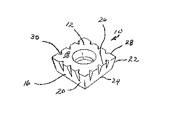
La présente invention vise une pastille de découpage indexable polygonale présentant un angle de coupe positif et un tranchant de forme sinusoïdale tronquée.


Abrégé anglais


A polygonal, indexable cutting insert having a positive rake
and a cutting edge having a truncated sinusoidal form.

Revendications

Note : Les revendications sont présentées dans la langue officielle dans laquelle elles ont été soumises.


CLAIMS
I Claims:
1. A polygonal, indexable cutting insert having a positive
rake, comprising;
a top surface and bottom surface substantially parallel
to each other and separated by a sidewall running substantially
unbroken therebetween to define a body, said sidewall comprised of
a plurality of side flank surfaces which are substantially planar,
each side flank surface extending from corner to corner of the
insert body, each side flank intersects the bottom surface along
its entire edge at an obtuse angle and the top surface along its
edge at an acute angle so that the insert has a positive rake
profile; said intersection of each side flank and the top surface
forms a cutting edge; each said cutting edge has a plurality of
equally spaced serrations having their center lines spaced a part
from each other; each serration being perpendicular to the top
surface and intersecting the side flank intermediate the width of
said side flank.
2. The insert of claim 1, wherein said serrations are
sinusoidal in shape.
3. The insert of claim 1, further including a centrally
located aperture in the top surface and extending through the body
of the insert, said aperture further equipped with a counterbore
at the top surface.
- 7 -

4. The insert of claim 2, wherein said sinusoidal serrations
are truncated below the mean line of the sinusoidal curve.
5. The insert of claim 1, wherein the insert is shaped as
a regular polygonal.
6. The insert of claim 1, wherein the positive rake of each
side flank is approximately 11°.
7. The insert of claim 1, wherein each corner is chamfer at
approximately 45° to 90°
8. In a cutting tool having a plurality of insert pockets,
each pocket having a seating surface and sidewalls, and means to
retain the insert in the pockets, a plurality of polygonal inserts
having a top surface and a bottom surface substantially parallel
to each other, said bottom surface adapted to seat on the seating
surface of the tool pocket, said top and bottom surface having a
sidewall extending substantially unbroken therebetween to define
a body, said sidewall comprised of a plurality of side flank
surfaces which are substantially planar, each side flank surface
extending from corner to corner of the insert body, each corner
being chamfered, each side flank intersects the bottom surface
along its entire edge at an obtuse angle and the top surface along
its entire edge at an acute angle so that the insert has a positive
rake profile; said intersection of each side flank said top surface
forms a cutting edge; each cutting edge having a plurality of
equally spaced, truncated serrations having their center liens
spaced from each other; each serration being perpendicular to the
- 8 -

top surface and intersecting the side flank intermediate the width
of said side flank; each said insert arranged in the cutting tool
in helical rows and each row is spaced apart from each other
according to the formula
Z = Y/2 - (S); wherein
Z is the chamfer of the insert;
Y is the serration below the mean line of the curve
S is the distance between inserts in the cutter
body.
9. The cutting tool of claim 8, wherein each corner of the
insert is chamfered at an angle between about 45° to 90°.
10. The cutting tool of claim 8, wherein the positive rake
of each side flank is about 11°.
11. The cutting tool of claim 8, wherein the insert further
includes a centrally located aperture in the top surface and
extending through the body of the insert, said aperture further
equipped with a counterbore at the top surface.
- 9 -

Description

Note : Les descriptions sont présentées dans la langue officielle dans laquelle elles ont été soumises.


-'- 2~6~
P08ITIY~ RA~E ~ hl
HA~ING 8B~RATION8 FOR ~u~.lNG
B~C~GROUND OF T~E l~v~h.ION
1. Field of the inventio~.
The present invention relates to a polygonal lay down
indexable insert for cutting metals which has a positive rake and
a truncated sinusoidal form along the cutting edge of the insert.
The present invention further relates to a ,polygonal form
indexable cutting insert having a positive rake, and a truncated
sinusoidal form along the cutting edge which intersects the top
surface of the insert at a right angle and intersect the flanks of
the insert at some point intermediate between the top and bottom
surfaces and which insert is capable of being formed by a
conventional pressing methods.
2. Description of the Related Art
Malinchak, U.S. Patent No. 3,875~Ç31 discloses a negative rake
insert having sinusoidal serrations along the entire width of the
cutting edge and flanks of the insert. Being a negative rake
insert, the insert provides for eight faces which may be used in
cutting operations. It is contemplated that the ~alinchak insert
~ay be used in concert with other inserts o~ like design such that
the insert6 are staggered according to a ~ormula and presented to
a metal piece f or cutting.

fi 3 2
Malinchak, U.S. Patent No. 3,922,766 discloses a cutting tool
having a plurality of inserts. EAch insert is in the form of a
circular disk or cylinder having a plurality of cutting teeth
disposed symmetrically around the outer periphery. The cutting
members are adjusted in the holder so that each tooth progressively
cuts behind the tooth ahead of it so that the peaks of one edge
cover a part of the trough of another edge whereby cutters
progressively cut an article. The cutters can be adjusted so that
as certain teeth wear, that the cutters can be rotated to bring
additional new teeth into cutting position.
8UMMARY OF ~HE lNv~h~loN
The present invention is a polygonal indexable insert having
a positive rake. The insert comprises a top and ~ottom surface
which are substantially parallel to each other and separated by a
sidewall running substantially unbroken therebetween to define a
body~ The sidewall is comprised of a plurality of side flank
surfaces which are substantiallv planar in shape. Each side flank
surface extends from corner to corner of the insert. Each side
flank surface intersects-the bottom surface along its edge at an
obtuse angle and intersects the top surface along its edge at an
acute angle so that the insert may be seen to have a positive rake
profile along each side flank. The intersection of each side flank
at the top surface forms a cutting edge. Each cutting edge has a
plurality of equally spaced serrations formed in each side of the
insert and having their center lines spaced apart from each other.

h ~ 3 2
Each serration is perpendicular at the top surface and intersects
the side flank at a point intermediate the width of the side flank
face. It is contemplated that the side flanks extend outwardly
from the bottom surface toward the top at approximately 11-.
The serrations are preferably sinusoidal in shape and are
truncated at each crest of the sinusoidal curve below the mean line
of the curve. ~lthough the insert may be any polygonal shape, it
is preferred that the insert is a regular shaped polygon and each
cutting edge is identical to the others. A centra~l aperture may
be provided to secure the insert in place.
BRIEF DESCRIP~ION OF ~ DRA~INGS
Figure 1 is a perspective top view of the insert of the
present invention.
Figure 2 is a top plan view of the insert showing a
configuration of the cutting edges.
Figure 3 is a cutaway view of the insert along lines 3 as
taken in Figure 2, showing the orientation of the sinusoidal curves
in the side flanks of the insert.
Figure 4 is a detailed view of the cutting edge of Figure 2
showing the truncated sinusoidal configuration of the cutting
insert.
DETAI~ED DESCR:CPTION OF 'r~13 PREF13RRED EIIBODIME~Nl!
Turning now to the drawings, wherein like numerals reference
like structures, insert 10 is comprised of a top surface 12, a
bottom surface 14, and a sidewall 16 extending substantially

unbroken therebetween to define a body 18. The insert is polygonal
in shape and is preferably a regular polygon. Each sidewall is
comprised of a side flank 20 which extends from corner to corner,
each designated as 22. Each side flank intersects the bottom
sur~ace at edge 24 and the top surface at edge 26. It should be
noted that the present invention relates to a positive rake insert.
Accordingly, the components side flanks intersect the bottom edge
at an obtuse angle and intersect the top edge at some abute angle.
The intersection of each side flank and the top surface forms the
cutting edge 28. Each cutting edge has a plurality of equally
spaced, preferably sinusoidal shaped serrations formed in each
cutting edge of the insert. The center lines of the sinusoidal
curves are spaced apart from each other. Each serration is
situated along the cutting edge and intersects the top surface
perpendicular to the surface itself and intersects the side ~lank
at some point intermediate the top a~d bottom surfaces. Turning
now to Figures 1 and 4, it can be seen that serrations 30 are
flattened at the crest of the curve whereas the roots of the curve
are intact. Thus, it can be seen that the sinusoidal curve is
truncated. By this term, it is meant that the crest of the curve
is ~lattened. Preferably, the curve is truncated below the mean
line o~ the sinu~oidal curve.
It is further understood that the insert described herein is
used in plurality in a cutting tool. Specifically, the inserts are
arranged in rows in insert pockets. Each pocket has seating

~0~3~
surface and side walls and the insert is fastened thereto. The
next row is arranged in tool pockets so that the relationship
between each row of inserts is best seen using the formula
Z = Y
S is the distance between inserts in the cutting tool body;
Z is the chamfer of the insert;
Y is the width of the serration below the mean line of the
sinusoidal curve. It is further preferred that the inserts are
arranged in helical rows is in the direction of cutting.
Turning now to Figure 4, the width of the serration portion
~yll is seen to differ from the width of truncated portion X. Thus,
it can be seen that by truncating the sinusoidal curve below the
mean line, X > Y. Similarly Z, which is the chamfer of the insert,
is .008" to .01" less than 1/2 the Y dimension so that when the
inserts are positioned in a cutter tool body, the X dimension of
an insert in an adjacent flute or row will overlap and cover the
spaca between adjacent inserts in the next row according to the
~ormula
2 Z ~ .015/.020 = Y
The positive rake insert of the present invention may further
be equipped with a central aperture to facilitate holding the
insert in a tool pocket holder.
Turning now to Figures 2 and 3. Figure 2 is a top plan view
of the insert. Note the central aperture 34 with counter bore 36

~r
2 1 ~ i 3
for fastening the insert into an insert pocket of a tool. Note
~hat each edge 28 is identical. However, those skilled in the art
recognize that the insert may be any polygonal shape and the sides
need not be identical.
Figure 3 is taken alo~g lines 3-~ of Figure 2 and shows a
cross section of the insert indicating the manner in which the
truncated sine curve serration intersects the top surface at 90 ,
as shown by line 30, and the side flank at some point along the
width of the side flank intermediate the top and bo,ttom edge.
Those skilled in the art will recognize that the invention
described herein is capable of many modifications and variations
without departing from the scope and spirit of the invention.

Dessin représentatif
Une figure unique qui représente un dessin illustrant l'invention.
États administratifs

2024-08-01 : Dans le cadre de la transition vers les Brevets de nouvelle génération (BNG), la base de données sur les brevets canadiens (BDBC) contient désormais un Historique d'événement plus détaillé, qui reproduit le Journal des événements de notre nouvelle solution interne.

Veuillez noter que les événements débutant par « Inactive : » se réfèrent à des événements qui ne sont plus utilisés dans notre nouvelle solution interne.

Pour une meilleure compréhension de l'état de la demande ou brevet qui figure sur cette page, la rubrique Mise en garde , et les descriptions de Brevet , Historique d'événement , Taxes périodiques et Historique des paiements devraient être consultées.

Historique d'événement

Description Date
Le délai pour l'annulation est expiré 2006-07-17
Inactive : CIB de MCD 2006-03-11
Lettre envoyée 2005-07-15
Accordé par délivrance 1998-07-07
Préoctroi 1998-03-23
Inactive : Taxe finale reçue 1998-03-23
Un avis d'acceptation est envoyé 1997-10-21
Lettre envoyée 1997-10-21
Un avis d'acceptation est envoyé 1997-10-21
Inactive : Renseign. sur l'état - Complets dès date d'ent. journ. 1997-10-15
Inactive : Dem. traitée sur TS dès date d'ent. journal 1997-10-15
Inactive : Approuvée aux fins d'acceptation (AFA) 1997-08-12
Symbole de classement modifié 1997-08-12
Inactive : CIB enlevée 1997-08-12
Inactive : CIB en 1re position 1997-08-12
Inactive : CIB attribuée 1997-08-12
Toutes les exigences pour l'examen - jugée conforme 1996-03-20
Exigences pour une requête d'examen - jugée conforme 1996-03-20
Demande publiée (accessible au public) 1994-02-04

Historique d'abandonnement

Il n'y a pas d'historique d'abandonnement

Taxes périodiques

Le dernier paiement a été reçu le 1997-06-30

Avis : Si le paiement en totalité n'a pas été reçu au plus tard à la date indiquée, une taxe supplémentaire peut être imposée, soit une des taxes suivantes :

  • taxe de rétablissement ;
  • taxe pour paiement en souffrance ; ou
  • taxe additionnelle pour le renversement d'une péremption réputée.

Les taxes sur les brevets sont ajustées au 1er janvier de chaque année. Les montants ci-dessus sont les montants actuels s'ils sont reçus au plus tard le 31 décembre de l'année en cours.
Veuillez vous référer à la page web des taxes sur les brevets de l'OPIC pour voir tous les montants actuels des taxes.

Historique des taxes

Type de taxes Anniversaire Échéance Date payée
TM (demande, 4e anniv.) - générale 04 1997-07-15 1997-06-30
Taxe finale - générale 1998-03-23
TM (brevet, 5e anniv.) - générale 1998-07-15 1998-07-13
TM (brevet, 6e anniv.) - générale 1999-07-15 1999-06-18
TM (brevet, 7e anniv.) - générale 2000-07-17 2000-06-21
TM (brevet, 8e anniv.) - générale 2001-07-16 2001-06-20
TM (brevet, 9e anniv.) - générale 2002-07-15 2002-06-20
TM (brevet, 10e anniv.) - générale 2003-07-15 2003-07-08
TM (brevet, 11e anniv.) - générale 2004-07-15 2004-06-25
Titulaires au dossier

Les titulaires actuels et antérieures au dossier sont affichés en ordre alphabétique.

Titulaires actuels au dossier
VALENITE INC.
Titulaires antérieures au dossier
PAUL ALLAIRE
Les propriétaires antérieurs qui ne figurent pas dans la liste des « Propriétaires au dossier » apparaîtront dans d'autres documents au dossier.
Documents

Pour visionner les fichiers sélectionnés, entrer le code reCAPTCHA :


Pour visualiser une image, cliquer sur un lien dans la colonne description du document (Temporairement non-disponible). Pour télécharger l'image (les images), cliquer l'une ou plusieurs cases à cocher dans la première colonne et ensuite cliquer sur le bouton "Télécharger sélection en format PDF (archive Zip)" ou le bouton "Télécharger sélection (en un fichier PDF fusionné)".

Liste des documents de brevet publiés et non publiés sur la BDBC .

Si vous avez des difficultés à accéder au contenu, veuillez communiquer avec le Centre de services à la clientèle au 1-866-997-1936, ou envoyer un courriel au Centre de service à la clientèle de l'OPIC.

({010=Tous les documents, 020=Au moment du dépôt, 030=Au moment de la mise à la disponibilité du public, 040=À la délivrance, 050=Examen, 060=Correspondance reçue, 070=Divers, 080=Correspondance envoyée, 090=Paiement})


Description du
Document 
Date
(aaaa-mm-jj) 
Nombre de pages   Taille de l'image (Ko) 
Revendications 1997-07-13 3 98
Revendications 1998-05-24 3 98
Revendications 1998-06-03 3 98
Revendications 1994-04-29 4 91
Abrégé 1994-04-29 1 5
Dessins 1994-04-29 1 19
Description 1994-04-29 6 188
Dessin représentatif 1998-07-07 1 5
Avis du commissaire - Demande jugée acceptable 1997-10-20 1 165
Avis concernant la taxe de maintien 2005-09-11 1 172
Correspondance 1998-03-22 1 41
Taxes 1997-06-29 1 43
Taxes 1998-07-12 1 41
Taxes 1996-06-23 1 47
Taxes 1995-07-03 1 44
Correspondance de la poursuite 1996-03-19 1 38
Correspondance reliée au PCT 1998-03-22 1 43
Correspondance de la poursuite 1997-06-23 1 29
Courtoisie - Lettre du bureau 1996-04-18 1 38
Demande de l'examinateur 1997-06-05 1 50