Note: Descriptions are shown in the official language in which they were submitted.
1523-3
2100853
FENCE SYSTEM
This invention relates to barriers and more
particularly to fences having horizontal rails supported by
metal posts.
Wooden fences are often preferred over chain link
fences for reasons of aesthetic appeal, or greater privacy
even though wooden fences are more expensive and require
greater maintenance.
It is, therefore, desirable to provide a wooden
fence which requires less skilled labour to construct and
less maintenance due to the fact that rotting of rails and
posts is reduced.
Attempts to provide a double post fence include a
stockyard fence disclosed in U.S. Patent 2,669,434 issued to
W. E. White. This fence was not entirely suitable for
replacing a residential wood fence system.
A residential fence system including bifurcated
posts set in a concrete-base, and horizontal rails passing
through the posts was disclosed in Canadian Patent 889,055
issued to Rudolph E. Parisien. It was pointed out in this
patent that there are advantages to be gained by passing top
and bottom rails through the post these advantages include
elimination of cutting and fitting rails between posts.
However, the prior attempts to provide a double
post fence system have not been entirely satisfactory in
(that accurate positioning of the upright members in the
concrete base is necessary otherwise on site drilling would
be required to provide aligned apertures extending through
both upright post members.
It is, therefore, desirable to provide a connector
for securing two post members together which requires no
- 2 -
~~00~53
holes to be drilled in the posts. The connector further
provides a vertically adjustable support for the horizontal
rails.
A further advantage of the connectors of this
invention is that in one mode of operation it is used to
align a pair of post members during pouring of the concrete
base in which the members are embedded.
A still further advantage of the fence post
connector of this. invention is that post members are wedged
against wood rails so that passing bolts through the posts
is unnecessary. It is also desirable to eliminate nails,
screws or similar means for fastening wooden rails to posts .
BRIEF STATEMENT OF THE INVENTION
Accordingly, the present invention provides a
plurality of vertical posts supporting top and bottom rails,
the post comprising parallel spaced-apart channel members
having lower ends embedded in concrete, a connector
comprising a body, an aperture in the body to receive a
bolt, a pair of ribs on the body, one of the ribs on each
side edge of the body to engage flanges on the channel
members, and a washer on the bolt for engaging side walls of
the channel members of the post when the post is assembled.
DESCRIPTION OF THE DRAWINGS
In the drawings which illustrate a preferred
embodiment of the invention:
Figure 1 is a perspective view of a fence system in
accordance with the invention;
Figure 2 is an end view of the fence of Figure showing
a concrete base attached to a line post;
Figure 3 is a top plan view of the post of Figure 2
showing a top rail in dashed lines;
Figure 4 is a perspective view of a section of a top
rail and a post having the connector of this invention
- 3 -
~1~D~~~~
installed thereon;
Figure 5 is a top plan view of the post of Figure 2 of
the fence post held in position while concrete is poured;
Figure 6 is a perspective view of an alternative
construction of the fence system;
Figure 7 is a top plan view of a fence system; and
Figures 8 and 9 are alternative constructions of the
band of Figure 6.
DETAILED DESCRIPTION OF THE INVENTION
Referring now in detail to the accompanying
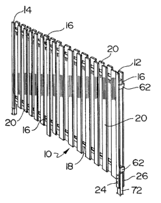
drawings a fence system shown generally at 10 in Figure 1
includes vertical posts, two of which are shown at 12 and 14
for supporting a top rail 16 and a bottom rail 18 to which
fence infill material 20, in this case wooden slats, is
secured.
Since rails 16 and 18 pass through posts 12 or 14,
it is not necessary to have posts 12 or 14 at regular
intervals, and rails 16 and 18 may be spliced as required.
Unforseen problems in providing post holes at exact
intervals can be avoided. Vertical adjustment of the rails
during construction, and for maintenance purposes due to
heaving of posts 12 and 14 caused by ground movement, is
facilitated by the vertically adjustable connectors 50 which
can be released to move rails 16 and 18 relative to posts 12
and 14.
As shown more clearly in Figure 2 each post 12
comprises parallel spaced-apart channel members 24 and 26
having their lower ends embedded in concrete base 28
constructed below grade and preferably extending below the
frost line in northern areas.
The channel member 24 and 26 are of identical C-
shaped cross-section and only one channel member will be
described in detail as shown in Figures 3, 4 and 5. The
- 4 -
zloog~~
channel member 24 has two side walls 30 and 32 and an
interconnecting wall 34. The outer edges of the walls 30
and 32 are turned inwardly to provide integral ribs or
flanges 36 and 38 on the walls 30 arid 32 respectively. A
reinforcing rib 40 is also provided on the inner face of the
connecting wall 34 if required.
It will be noted that the flanges 36 and 38 have
angled inner faces 42 and '44 so as to be at an angle of
approximately 95° to 100° relative to the side walls 30 and
32 respectively.
The channel members 24 and 26 are held together at
the upper end by one or more connectors 50 as shown in
Figure 3. The connector 50 has a body 52 having a centrally
located aperture 54 to receive a bolt 56. The side edges of
the body 52 are bent substantially at right angles to
provide flanges 58 to cooperate with surfaces 42 and 44 of
the flanges 36 and 38 of the channel members 24 and 26.
As shown in Figure 4 the assembled post 14
includes channel members 24 and 26 supporting a rail 16 of
wood, metal or other suitable material (shown in dashed
lines in Figure 3). As shown in Figure 5, the connector 50
includes a washer 62 received on the bolt 56 and engaging
the channel members 24 and 26. A retaining nut 64 is
received on the end of the bolt 56.
During assembly of the post 14, and the pouring of
the concrete base 28, the channel members 24 and 26 are
conveniently held in parallel spaced apart relationship by
the connector 50 which is temporarily reversed and bolted in
place as shown iri Figure 5. It will be appreciated that
parallel grooves 70 in the body of the connector 50 engage
the flanges 36 and 38 of the channel members 24 and 26 to
provide accurate alignment during pouring and hardening of
the concrete base 28.
- 5 -
CA 02100853 2002-11-06
Alternatively, the channel members 24 and 26 can
be fastened to a stub post 72 (shown in Figure 1) driven
into the ground or embedded in a concrete base, and i.t is
considered that such a construction for the past 14 would be
within the scope of the invention.
As shown in Figures 6 and 7, a clamp or band 100
is substituted for the connector 50 of Figure 1. The post
114 includes channel members 124 and 126 supporting the rail
16. The band 100 is preferaY~ly formed in two pieces 128,
130 held together by bolts 136 and retaining nuts 138.
It will be appreciated that the construction of
the band 100 may vary and two variations are shown at 200
and 210 in Figures 8 and 9 respectively. The band 200 is
similar to the band 100 of Figure 6 although .it is adapted
for use with a single bolt 136. The band 210 is a two piece
band having a single bolt 220 extending therethrough.
Alternatively, when using bands 100, 200 or 210
instead of brackets ~~0, rather than the bands having the
dual purpose of acting as fastener and installation sparing
tool, this construction required either the actual rails to
be positioned within the posts, or~ a temporary block of rail
to be positioned within the po:;ts which posts are being
installed in a concrete base 28 (Figure 2j.