Note: Descriptions are shown in the official language in which they were submitted.
2100911
LOOP DISTRIBUTOR FOR REFORMING STATION
File: D-991
I~ACKGROUND OF T~E INVENTION
1. Field of the rnvention
This invention relates generally to reforming stations in a wire rod mill, and is concerned
S in particular with an improved means for distributing wire rod loops as they are being received
from the delivery end of a cooling conveyor and accumulated in coil form.
2. Description of the Prior Art
In a typical wire rod mill inst~ tion, as indicated schem~tic~lly in Figure 1, billets are
10 reheated in a furnace 10, and then are continuously hot rolled through roughing, intermediate
and finiching sections 12, 14 and 16 of the mill. The finished wire rod is then prelimin~rily
cooled in water boxes 18 before being formed into loops L by a laying head 20. The loops are
received in an overlapping arrangement on a cooling conveyor 22 where they are subjected to
further controlled cooling. Thereafter, the loops drop from the delivery end of the conveyor into
15 a reforrning station 24 where they are gathered into upst~n~1ing cylindrical coils. The coils are
then compacted, banded and transferred to other locations (not shown) for further processing or
shipment to off site customers.
As the loops drop into the refo~ ing station, their oriPnt~tion with respect to each other
has an effect on the shape and size of the resul~ing coil. For example, if the loops are allowed
20 to pile up at one side, the coil is likely to be lopsided and unstable. It is desirable, therefore,
to achieve a uniform distribution of succe~cive loops around the circumference of the coil as it
is being formed. In this way, the coil takes on a more stable configuration, and subsequent
compaction will result in increased density, thereby minimi7ing the space occupied by the coils
during ~ansit and storage.
2loo9ll
U.S. Patent No. Re. 26,052 discloses one attempt at
achieving improved loop distribution through the use of a
rotating deflector arm extending radially inwardly towards the
center of the reforming chamber, with its innermost surface
spaced from the opposite side of the chamber by a distance
substantially equal to the diameter of the descending loops.
Theoretically, this arrangement can operate satisfactorily as
long as the loops follow a more or less constant path of
descent. However, under actual operating conditions in a
rolling mill environment, the loops can and often do stray from
one path, thus presenting a danger that they will hang up on
the arm. When this occurs, subsequent loops will rapidly pile
up above the rotating arm, the result being an uncontrolled
tangle necessitating a complete shutdown.
Summary of the Invention
According to an aspect of the present invention, there is
provided, in an apparatus for receiving a series of loops
descending along a vertical path from a delivery device, and
for accumulating the thus received loops in the form of an
annular coil, a device for horizontally distributing the loops
as they descend into the apparatus, said device comprising:
a) means defining a circular path surrounding said
vertical path;
b) a rotatable guide member having a three dimensionally
shaped guide face, said guide face having: (i) a top edge
extending from a front end to a rear end along a segment of
said circular path; (ii) a trailing edge extending downwardly
from said rear end to a lower end; and (iii) a leading edge
2100911
extending upwardly from said lower end and angularly with
respect to said trailing edge to said front end, said guide
face extending into said vertical path and being arranged to be
contacted by and to horizontally deflect the descending loops
away from the said segment of said circular path; and
c) means for rotating said guide member around said
circular path to circumferentially distribute the thus
deflected loops around the axis of the accumulating annular
coil.
Brief Description of the Drawings
Figure 1 is a diagrammatic illustration of a
conventional wire rod mill;
Figure 2 is a plan view on an enlarged scale looking
down into a reforming station of the type employing a loop
distributing device according to the present invention;
Figures 3 and 4 are sectional views taken
respectively along lines 3-3 and 4-4 of Figure 2;
Figure 5 is a diagrammatic illustration depicting the
three dimensionally curved guide surface of the present
invention as a segment of the interior surface of an inverted
hollow cone;
Figure 6 is a illustration depicting the general
position of the guide surface and its circular path of travel
in relation to the path of loop descent into the reforming
chamber;
D
2tOO91l
Figure 7 is a diagrammatic illustration of the ~1im~n~ional relationship of various
components; and
Figure 8 is another diagrammatic illustrations of the guiding action provided by the guide
surface.
DETAILED DESCR~PTION OF PREFERRED EMBODIMENT
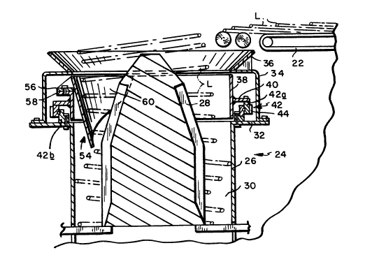
With reference initially to Figures 2-4, the lefol.-ling station 24 is shown comprising a
cylindrical stationary tub 26 cooperating with an upst~n~in~ center guide 28 to define an annular
coil forming charnber 30. A horizontal shelf 32 surrounds the exterior of the tub. Shelf 32
supports braclcet 34 which in turn carries a trl~nr~t~ conical entry port 36 through which the
loops L are received from the delivery end of the conveyor 22. A cylindrical sleeve 38 is
interposed between the upper end of the tub 26 and the bottom end of the entry port 36. Sleeve
38 has a radially outwardly extending circular bracket 40 ca~Tying the outer race 42a of a
circular roller bearing 42, the inner race 42b of the bearing being mounted to the shelf 32. The
outer race 42a has teeth 44 engageable with a pinion 46 carried on a shaft 48 protruding
downwardly from a drive housing 50 secured to the braclcet 34. A motor 52 within the drive
housing 50 is coupled to the shaft 48 and serves as the means for rotatably driving the sleeve
38. The upper edge of the sleeve defines a circular path Pa s~ ou.lding the path Pb of loop
20 descPnt into the annular chamber 30. The rel~tinnchir of the circular path Pa to the path Pb of
loop desc~nt is sc~ tiç~lly depicted in Figure 6.
A guide member 54 is mounted by means of an eYtPrn~l bIacket 56 to a lip 58 on the
sleeve 38 for rotation therewith. The guide mpmber s4 has a three ~im~n~ionally curved guide
B
2100911
surface 60 extending into the path of loop descent. As can best be seen in Figure 5, the guide
surface 60 preferably defines a segment of the interior of an inverted hollow reference cone 62.
With reference In particular to Figure 4, it will be seen that the guide surface 60 has a
top edge 60a extending from a front end 60b to a rear end 60c along a segment of the circular
5 path Pa. A trailing edge 60d extends downwardly from the rear end 6ac to a lower end 60e.
A leading edge 60f extends upwardly from the lower end 60e and angularly with respect to the
trailing edge 60d to the front end 60b. Preferably, the slope of the leading edge 60f changes
at 60g to define a more sharply angled portion adjacent to the front end 60b.
- With reference to Figure 7, it will be seen that the leading end 60b of the guide surface
10 60 is spaced from the opposite surface of the tub 26 by a first distance d I, which is
a~lo~imately equal to the outer diameter Da f the annular refoll"ing chamber 30. The lower
end 60e of guide surface 60 is spaced from the inner tub ~i~met~r by a second distance d2 which
is less than dl, but somewhat greater than the ~ m~ter of the loops L being received in the
chamber. Preferably,
d2 = Da-Db + Db + C
Where: Da = outer diameter of chamber 30
Db = inner diameter of chamber 30
C = clearance constant
With this arrangement, as each loop descen-is into the lefol~ g charnber, it will fall free
of the leading end 60b of the guide surface, with initial contact with the guide surface occu-ring
25 behind the leading end and below the upper edge 60a, typically along a peripheral segment of
-
2100911
the loop indicated schem~tic~lly in Figure 7 as well as in Figure 8 at Ls. As the loop slides
downwardly across the guide surface 60, and the guide surface is rotated in the direction R, the
peripheral segment Ls will gradually ~iminich until the loop falls free of the lower end 60e~ e
net result is that the loop is gradually and smoothly urged away from the guide surface towards
S the opposite surface of the tub wall. By c~nt~cting each loop along a peripheral segment, the
loops are prevented from rolling across the guide surface and thus disturbing the guiding action.
This effect is imparted to successive loops as the guide surface continues to rotate around the
circumference of the tub, thus producing a uniforrn distribution of rings in a controlled
overlapping relationship. The front end 60b of the guide surface remains outboard of the
10 descending loops, which insures that leading edge 60f does not come into d~m~ging contact with
the loops.
I claim: