Language selection

Search

Patent 2101027 Summary

Third-party information liability

Some of the information on this Web page has been provided by external sources. The Government of Canada is not responsible for the accuracy, reliability or currency of the information supplied by external sources. Users wishing to rely upon this information should consult directly with the source of the information. Content provided by external sources is not subject to official languages, privacy and accessibility requirements.

Claims and Abstract availability

Any discrepancies in the text and image of the Claims and Abstract are due to differing posting times. Text of the Claims and Abstract are posted:

  • At the time the application is open to public inspection;
  • At the time of issue of the patent (grant).
(12) Patent: (11) CA 2101027
(54) English Title: ACTIVE ACOUSTIC ATTENUATION AND SPECTRAL SHAPING SYSTEM
(54) French Title: SYSTEME D'ATTENUATION ACOUSTIQUE ACTIVE ET DE MISE EN FORME SPECTRALE
Status: Deemed expired
Bibliographic Data
(51) International Patent Classification (IPC):
  • G10K 11/16 (2006.01)
  • G10K 11/178 (2006.01)
  • G10K 15/00 (2006.01)
(72) Inventors :
  • POPOVICH, STEVEN R. (United States of America)
  • ALLIE, MARK C. (United States of America)
(73) Owners :
  • NELSON INDUSTRIES, INC. (United States of America)
(71) Applicants :
  • NELSON INDUSTRIES, INC. (United States of America)
(74) Agent: BORDEN LADNER GERVAIS LLP
(74) Associate agent:
(45) Issued: 1999-04-06
(22) Filed Date: 1993-07-21
(41) Open to Public Inspection: 1994-01-28
Examination requested: 1995-05-09
Availability of licence: N/A
(25) Language of filing: English

Patent Cooperation Treaty (PCT): No

(30) Application Priority Data:
Application No. Country/Territory Date
920,259 United States of America 1992-07-27

Abstracts

English Abstract


An active acoustic system provides attenuation
and spectral shaping of an acoustic wave. A phase lock
loop (304) phase locks to the input acoustic wave (6) and
generates (306) a desired signal or tone (308) in given
phase relation therewith. An error signal (44) from an
error transducer or microphone (16) is summed (302) with
the desired signal (308) and the resultant sum is
supplied to the error input (202) of an adaptive filter
model (40) which outputs a correction signal (46) to an
output transducer or speaker (14) to introduce the
canceling and shaping acoustic wave. In other embodiments,
various combinations sum the desired signal (308) with
the error signal (44), the model output correction signal
(46), and the model input signal (42). Speaker and error
path compensation (146, 318, 320) and feedback compensation
(340) is provided.


French Abstract

L'invention est un système acoustique actif servant à affaiblir les ondes acoustiques et à les soumettre à une mise en forme spectrale. Une boucle à asservissement de phase (304) s'asservit à une onde acoustique d'entrée (6) et produit (306) un signal ou une tonalité (308) désiré ayant une relation de phase donnée avec cette onde acoustique. Un signal d'erreur (44) provenant d'un transducteur ou d'un microphone de détection d'erreurs (16) est sommé (302) avec le signal désiré (308) et la somme résultante est transmise à l'entrée de signaux d'erreur (202) d'un filtre adaptatif (40), lequel transmet un signal de correction (46) à un transducteur ou à un haut-parleur de sortie (14) pour supprimer l'onde acoustique et la conformer. D'autres concrétisations de l'invention utilisent diverses combinaisons de sommation du signal désiré (308) avec le signal d'erreur (44), le signal de correction (46) produit par le filtre et le signal d'entrée (42) du filtre. Le système corrige également les erreurs dans les signaux transmis au haut-parleur (146, 318, 320) et a recours à la rétroaction (340).

Claims

Note: Claims are shown in the official language in which they were submitted.


THE EMBODIMENTS OF THE INVENTION IN WHICH AN EXCLUSIVE
PROPERTY OR PRIVILEGE IS CLAIMED ARE DEFINED AS FOLLOWS:

1. An active acoustic attenuation and spectral shaping system for attenuating and
spectrally shaping an input acoustic wave comprising an output transducer introducing a
canceling and shaping acoustic wave to attenuate and shape said input acoustic wave and
yield an attenuated and spectrally shaped output acoustic wave, an error transducer sensing
said output acoustic wave and providing an error signal, an adaptive filter model modeling
said acoustic system and having an error input and outputting a correction signal to said
output transducer to introduce the canceling and shaping acoustic wave, a phase lock loop
phase locked to said input acoustic wave and generating a desired signal in given phase
relation with said input acoustic wave, a summer summing the error signal from said error
transducer and the desired signal from said phase lock loop and supplying the resultant
sum to said error input of said model such that said model outputs said correction signal to
said output transducer to introduce the canceling and shaping acoustic wave, wherein said
model outputs said correction signal to said output transducer such that said desired signal
is present in said output acoustic wave and in the error signal from said error transducer to
said summer such that the desired signal from said error transducer is canceled at said
summer by the desired signal from said phase lock loop and such that said desired signal
is absent from said error input to said model, and wherein said desired signal is present in
said correction signal.
2. The system according to claim 1 wherein said phase lock loop has an input from
said error signal, and phase locks to said input acoustic wave by phase locking to said
output acoustic wave by phase locking to said error signal to generate said desired signal
in given phase relation with said input signal.
3. An active acoustic attenuation and spectral shaping system for attenuating and
spectrally shaping an input acoustic wave comprising an output transducer introducing a
canceling and shaping acoustic wave to attenuate and shape said input acoustic wave and
yield an attenuated and spectrally shaped output acoustic wave, an error transducer sensing
said output acoustic wave and providing an error signal, an adaptive filter model modeling
said acoustic system and having an error input and outputting a correction signal to said
output transducer to introduce the canceling and shaping acoustic wave, a phase lock loop
phase locked to said input acoustic wave and generating a desired signal in given phase

relation with said input acoustic wave, a first summer summing the error signal from said
error transducer and the desired signal from said phase lock loop and supplying the
resultant sum to said error input of said model such that said model outputs said correction
signal to said output transducer to introduce the canceling and shaping acoustic wave, a
second summer summing said desired signal from said phase lock loop with said
correction signal from said model and outputting the resultant sum to said output
transducer such that said desired signal is present in said output acoustic wave and in the
error signal from said error transducer to said first summer and such that said desired
signal from said error transducer is canceled at said first summer by said desired signal
from said phase lock loop and such that said desired signal is absent from said error input
to said model from said first summer.
4. An active acoustic attenuation and spectral shaping system for attenuating and
spectrally shaping an input acoustic wave comprising an output transducer introducing a
canceling and shaping acoustic wave to attenuate and shape said input acoustic wave and
yield an attenuated and spectrally shaped output acoustic wave, an error transducer sensing
said output acoustic wave and providing an error signal, an adaptive filter model modeling
said acoustic system and having an error input and outputting a correction signal to said
output transducer to introduce the canceling and shaping acoustic wave, a phase lock loop
phase locked to said input acoustic wave and generating a desired signal in given phase
relation with said input acoustic wave, a summer summing the error signal from said error
transducer and the desired signal from said phase lock loop and supplying the resultant
sum to said error input of said model such that said model outputs said correction signal to
said output transducer to introduce the canceling and shaping acoustic wave, an auxiliary
noise source introducing auxiliary noise such that said error transducer also senses the
auxiliary noise from said auxiliary noise source, a second adaptive filter model having a
model input from said auxiliary noise source and modeling said output transducer and the
error path between said output transducer and said error transducer, and a copy of said
second adaptive filter model having an input from said phase lock loop and having an
output to said summer, such that the desired signal is supplied through said copy to the
summer.
5. The system according to claim 4 comprising a second copy of said second adaptive
filter model having an input from said correction signal and having an output, a second
summer having a first input from the error signal from said error transducer and a second

input from the output of said second copy of said second adaptive filter model, said
second summer having an output to said phase lock loop.
6. An active acoustic attenuation and spectral shaping system for attenuating and
spectrally shaping an input acoustic wave comprising an output transducer introducing a
canceling and shaping acoustic wave to attenuate and shape said input acoustic wave and
yield an attenuated and spectrally shaped output acoustic wave, an error transducer
sensing said output acoustic wave and providing an error signal, an adaptive filter model
modeling said acoustic system and having an error input and outputting a correction signal
to said output transducer to introduce the canceling and shaping acoustic wave, a phase
lock loop phase locked to said input acoustic wave and generating a desired signal in given
phase relation with said input acoustic wave, a first summer summing the error signal from
said error transducer and the desired signal from said phase lock loop and supplying the
resultant sum to said error input of said model such that said model outputs said correction
signal to said output transducer to introduce the canceling and shaping acoustic wave, a
second summer summing said desired signal from said phase lock loop with said
correction signal from said model and outputting the resultant sum to said output
transducer such that said desired signal is present in said output acoustic wave and in the
error signal from said error transducer to said first summer and such that said desired
signal from said error transducer is canceled at said first summer by said desired signal
from said phase lock loop and such that said desired signal is absent from said error input
to said model from said first mentioned summer, an auxiliary noise source introducing
auxiliary noise such that said error transducer also senses the auxiliary noise from said
auxiliary noise source, a second adaptive filter model having a model input from said
auxiliary noise source and modeling said output transducer and the error path between
said output transducer and said error transducer, and a copy of said second adaptive filter
model having an input from said phase lock loop and having an output to said first
summer, such that the desired signal is supplied through said copy to the first summer, a
second copy of said second adaptive filter model having an input from said correction
signal and having an output, a third summer having a first input from the error signal from
said error transducer and a second input from the output of said second copy of said
second adaptive filter model, said third summer having an output to said phase lock loop.
7. An active acoustic attenuation and spectral shaping system for attenuating and
spectrally shaping an input acoustic wave comprising an output transducer introducing a

canceling and shaping acoustic wave to attenuate and shape said input acoustic wave and
yield an attenuated and spectrally shaped output acoustic wave, an error transducer sensing
said output acoustic wave and providing an error signal, an adaptive filter model modeling
said acoustic system and having an error input and outputting a correction signal to said
output transducer to introduce the canceling and shaping acoustic wave, a phase lock loop
phase locked to said input acoustic wave and generating a desired signal in given phase
relation with said input acoustic wave, a summer summing the error signal from said error
transducer and the desired signal from said phase lock loop and supplying the resultant
sum to said error input of said model such that said model outputs said correction signal to
said output transducer to introduce the canceling and shaping acoustic wave, an auxiliary
noise source introducing auxiliary noise such that said error transducer also senses the
auxiliary noise from said auxiliary noise source, a second adaptive filter model having a
model input from said auxiliary noise source and modeling said output transducer and the
error path between said output transducer and said error transducer, a first copy of said
second adaptive filter model having an input from said phase lock loop and having an
output adding with the error signal at the summer, such that the desired signal is supplied
through said first copy to the summer, a second copy of said second adaptive filter model
having an input from said correction signal and having an output, a second summer
summing said correction signal and the desired signal from said phase lock loop and
supplying the resultant sum to said output transducer, a third summer summing the error
signal from said error transducer and the output of said second copy of said second
adaptive filter model and supplying the resultant sum to said phase lock loop for
generating said desired signal.
8. An active acoustic attenuation and spectral shaping system for attenuating and
spectrally shaping an input acoustic wave comprising an output transducer introducing a
canceling and shaping acoustic wave to attenuate and shape said input acoustic wave and
yield an attenuated and spectrally shaped output acoustic wave, an error transducer sensing
said output acoustic wave and providing an error signal, an adaptive filter model modeling
said acoustic system and having an error input and outputting a correction signal to said
output transducer to introduce the canceling and shaping acoustic wave, a phase lock loop
phase locked to said input acoustic wave and generating a desired signal in given phase
relation with said input acoustic wave, a summer summing the error signal from said error
transducer and the desired signal from said phase lock loop and supplying the resultant

sum to said error input of said model such that said model outputs said correction signal to
said output transducer to introduce the canceling and shaping acoustic wave, a signal
generator having an input from said phase lock loop and an output providing said desired
signal.
9. The system according to claim 1 wherein said model outputs said correction signal
to said output transducer such that said desired signal is present in said output acoustic
wave and in the error signal from said error transducer to said summer such that the
desired signal from said error transducer is canceled at said summer by the desired signal
from said phase lock loop and such that said desired signal is absent from said error input
to said model.
10. The system according to claim 9 wherein said desired signal is absent from said
correction signal.
11. An active acoustic attenuation and spectral shaping system for attenuating and
spectrally shaping an input acoustic wave comprising an output transducer introducing a
canceling and shaping acoustic wave to attenuate and shape said input acoustic wave and
yield an attenuated and spectrally shaped output acoustic wave, an error transducer sensing
said output acoustic wave and providing an error signal, an adaptive filter model modeling
said acoustic system and having an error input and outputting a correction signal, a first
summer summing the error signal from said error transducer and a desired signal and
supplying the resultant sum to said error input of said model, a second summer summing
said correction signal from said model and said desired signal and outputting the resultant
sum to said output transducer.
12. The system according to claim 11 comprising a second model modeling said output
transducer and the error path between said output transducer and said error transducer, and
a first copy of said second model having an input from said desired signal and an output
to said first summer such that said desired signal is supplied through said first copy to said
first summer.
13. The system according to claim 12 comprising a second copy of said second model
having an input from said correction signal and having an output, a third summer summing
the error signal from said error transducer and said output of said second copy of said
second model and supplying the resultant sum to said first copy of said second model as
the desired signal.

14. The system according to claim 13 wherein said resultant sum from said third
summer is supplied through a signal generator to said first copy of said second model.
15. The system according to claim 11 comprising a second model modeling said output
transducer and the error path between said output transducer and said error transducer, and
an inverse copy of said second model having an input from said desired signal and an
output to said second summer.
16. An active acoustic attenuation and spectral shaping system for attenuating and
spectrally shaping an input acoustic wave comprising an output transducer introducing a
canceling and shaping acoustic wave to attenuate and shape said input acoustic wave and
yield an attenuated and spectrally shaped output acoustic wave, an error transducer sensing
said output acoustic wave and providing an error signal, a first adaptive filter model
modeling said acoustic system and having an error input and outputting a correction signal
to said output transducer to introduce the canceling and shaping acoustic wave, a second
model modeling said output transducer and the error path between said output transducer
and said error transducer, a copy of said second model having an input from saidcorrection signal and having an output, a first summer summing the error signal from said
error transducer and said output of said copy of said second model, a second summer
summing the error signal from said error transducer and the output of said first summer
and supplying the resultant sum to said error input of said first model.
17. The system according to claim 16 wherein said output of said first summer issupplied through a signal generator to said second summer.
18. An active acoustic attenuation and spectral shaping system for attenuating and
spectrally shaping an input acoustic wave comprising an output transducer introducing a
canceling and shaping acoustic wave to attenuate and shape said input acoustic wave and
yield an attenuated and spectrally shaped output acoustic wave, an error transducer sensing
said output acoustic wave and providing an error signal, a first adaptive filter model
modeling said acoustic system and having a model input receiving an input signal, an error
input, and a model output outputting a correction signal to said output transducer to
introduce the canceling and shaping acoustic wave, a first summer, a second summer
summing said correction signal from said first model and a desired signal and outputting
the resultant sum to said output transducer, an auxiliary noise source introducing auxiliary
noise such that said error transducer also senses the auxiliary nose from said auxiliary
noise source, a second adaptive filter model having a model input from said auxiliary

noise source and modeling said output transducer and the error path between said output
transducer and said error transducer, a copy of said second adaptive filter model having an
input from said desired signal, said first summer summing the output of said copy of said
second model and the error signal from said error transducer and supplying the resultant
sum to said error input of said first model, a third adaptive filter model having a model
input from said auxiliary noise source and a model output summed at a third summer with
said input signal, and supplying the result of the third summer to the model input.
19. The system according to claim 18 comprising a copy of said third adaptive filter
model having an input from the output of said second summer and having an output, and a
fourth summer summing said output of said copy of said third adaptive filter model and
said output of said third summer and supplying the resultant sum to said model input of
said first adaptive filter model.
20. The system according to claim 19 comprising a fifth summer having a first input
from said output of said second summer and having a second input from said auxiliary
noise source and supplying the resultant sum to said output transducer.
21. An active acoustic attenuation and spectral shaping system for attenuating and
spectrally shaping an input acoustic wave comprising an output transducer introducing a
canceling and shaping acoustic wave to attenuate and shape said input acoustic wave and
yield an attenuated and spectrally shaped output acoustic wave, an error transducer sensing
said output acoustic wave and providing an error signal, an adaptive filter model modeling
said acoustic system and having a model input receiving an input signal, an error input,
and a model output outputting a correction signal to said output transducer to introduce the
canceling and shaping acoustic wave, a first summer summing the error signal from said
error transducer and a desired signal and supplying the resultant sum to said error input of
said model, a second summer summing said desired signal and said input signal and
supplying the resultant sum to said model input.
22. The system according to claim 21 comprising an auxiliary noise source introducing
auxiliary noise such that said error transducer also senses the auxiliary noise from said
auxiliary noise source, a second adaptive filter model having a model input from said
auxiliary noise source and a model output summed at a third summer with said input
signal, a copy of said second adaptive filter model having an input from said correction
signal and having an output summed with said input signal at a fourth summer having an
output resultant sum supplied to said second summer for summing with said desired signal.

23. An active acoustic attenuation and spectral shaping system for attenuating and
spectrally shaping an input acoustic wave comprising an output transducer introducing a
canceling and shaping acoustic wave to attenuate and shape said input acoustic wave and
yield an attenuated and spectrally shaped output acoustic wave, an error transducer sensing
said output acoustic wave and providing an error signal, a first adaptive filter model
modeling said acoustic system and having an error input and outputting a correction signal
to said output transducer to introduce the canceling and shaping acoustic wave, a signal
generator generating a desired signal, a first summer summing the error signal from said
error transducer and said desired signal and supplying the resultant sum to said error input
of said model, a second model modeling said output transducer and the error path between
said output transducer and said error transducer, a copy of said second model having an
input from said correction signal and having an output, a second summer summing the
error signal from said error transducer and said output of said copy and outputting the
resultant sum to said signal generator.
24. An active acoustic system for modifying an input acoustic wave to yield an output
acoustic wave, comprising an error transducer sensing said output acoustic wave and
providing an error signal, a first adaptive filter model having an error input responsive to
said error signal and providing a correction signal, an output transducer responsive to said
correction signal and introducing a modifying acoustic wave to combine with said input
acoustic wave to generate said output acoustic wave, a second adaptive filter model
modeling at least one of said output transducer and the error path between said output
transducer and said error transducer, a signal generator responsive to said second adaptive
filter model and to said error signal and generating a desired signal and combining said
desired signal with said error signal provided to said error input of said first adaptive filter
model.
25. An active acoustic system for modifying an input acoustic wave to yield an output
acoustic wave, comprising an error transducer sensing said output acoustic wave and
providing an error signal, an adaptive filter model having a model input responsive to an
input signal and an error input responsive to said error signal and providing a correction
signal, an output transducer responsive to said correction signal and introducing a
modifying acoustic wave to combine with said input acoustic wave to generate said output
acoustic wave, a signal generator generating a desired signal and combining said desired
signal with said error signal at a first combiner and combining said desired signal with

said correction signal at a second combiner, the result from the first combiner being
supplied to the error input and the result from the second combiner being supplied to the
output transducer, such that said desired signal is present in said output acoustic wave but
absent from said error input to said adaptive filter model due to said combining of said
desired signal and said error signal.
26. An active acoustic system for modifying an input acoustic wave to yield an output
acoustic wave, comprising an error transducer sensing said output acoustic wave and
providing an error signal, an adaptive filter model having a model input responsive to an
input signal and an error input responsive to said error signal and providing a correction
signal, an output transducer responsive to said correction signal and introducing a
modifying acoustic wave to combine with said input acoustic wave to generate said output
acoustic wave, a signal generator generating a desired signal and combining said desired
signal with said error signal at a first combiner and combining said desired signal with
said input signal at a second combiner, the result from the first combiner is supplied to the
error input and the result from the second combiner is supplied to the model input, such
that said desired signal is present in said output acoustic wave but absent from said error
input to said adaptive filter model due to said combining of said desired signal and said
error signal.

Description

Note: Descriptions are shown in the official language in which they were submitted.


-1- 2 7~ a~
ACTIVE ACOUSTIC A,l-~NuATION AND SPECTRAL SHAPING SYSTEM


BACKGROUND AND SUMMARY
The invention relates to active acoustic atten-
uation systems, and provides a system for attenuating and
spectrally shaping an acoustic wave.
The invention arose during continuing develop-
ment efforts relating to the subject matter shown and
described in U.S. Patents 4,677,676, 4,677,677,
4,736,431, 4,815,139, 4,837,834, 4,987,598, 5,022,082,
and 5,033,082~ ~ ~
Active attenuation involves injecting a cancel-
ing acoustic wave to destructively interfere with andcancel an input acoustic wave. In an active acoustic
attenuation system, the output acoustic wave is sensed
with an error transducer such as a microphone which
supplies an error signal to a control model which in turn
supplies a correction signal to a canceling transducer
such as a loudspeaker which injects an acoustic wave to
destructively interfere with and cancel the input acous-
tic wave. The acoustic system is modeled with an adap-
tive filter model.
In the invention of commonly owned U.S. Patent No
5,172,416, the error signal from the error transducer, e g
error microphone, is specified to correspondingly specify
the output acoustic wave. The error signal is specified
by summing the error signal with a desired signal to
provide an error signal to the error input of the system
model such that the model outputs the correction signal
to the output transducer, e.g. spea~er, to introduce the
canceling acoustic wave such that the desired signal is
present in the output acoustic wave. This provides a
desired sound rather than complete cancellation.
The present invention provides further improve-
ments for spectrally shaping the acoustic wave.

,
.

- 2 - 7 ~
In one aspect of the present invention, the
system includes a phase lock loop phase locked to the
input acoustic wave, and generates a desired signal in
given phase relation therewith. The error signal from
S the error transducer is summed with the desired signal
from the phase lock loop, and the resultant sum is sup-
plied to the error input of the model such that the model
outputs the correction signal to the output transducer to
introduce the canceling and shaping acoustic wave.
In another aspect, a first summer sums the
error signal from the error transducer with a desired
signal and supplies the resultant sum to the error input
of the model, and a second summer sums the correction
signal from the model with the desired signal and sup-
plies the resultant sum to the output transducer.
In a further aspect, another summer sums the
error signal from the error transducer with the correc-
tion signal supplied through a copy of a model of the
output transducer and error path and supplies the resul-
tant sum to the first summer.
In another aspect, the desired signal is sup-
plied through a copy of a model of the output transducer
and error path to the first summer.
In a further aspect, the desired signal is
supplied through an inverse of a copy of a model of the
output transducer and error path to the second summer.
In another aspect, a first summer sums the
error signal from the error transducer with a desired
signal and supplies the resultant sum to the error input
of the model, and a second summer sums the input signal
to the model with the desired signal and supplies the
resultant sum to the model input.
BRIEF DESCRIPTION OF THE DRAWINGS
FIG. 1 is a schematic illustration of an active
acoustic attenuation system in U S Patent No 5,172,416

_ - 3 _ ~ 7
FIGS. 2-5 are graphs illustrating operation of
the system of FIG. 1.
FIG. 6 is like FIG. 1 and shows an alternate
embodiment.
FIG. 7 is a schematic illustration of an active
acoustic attenuation system in accordance with the pres-
ent invention.
FIG. 8 is like FIG. 7 and shows a further
embodiment.
FIG. 9 is like FIG. 7 and shows a further
embodiment.
FIG. 10 is like FIG. 7 and shows a further
embodiment.
FIG. 11 is like FIG. 7 and shows a further
embodiment.
FIG. 12 is like FIG. 7 and shows a further
embodiment.
FIG. 13 is like FIG. 7 and shows a further
embodiment.
FIG. 14 is a schematic illustration of an acoustic
system or plant as illustrated in FIG. 20 of U.S. Patent
4,677,676.
DETAILED DESCRIPTION
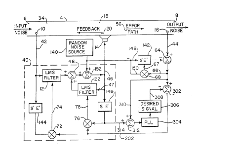
FIG. 1 shows an active acoustic attenuation system
like that shown in FIG. 19 of U.S. Patent 4,677,676, but
modified in accordance with the invention of U.S. Patent
5,172,416.
The acoustic system in FIG. 1 has an input 6
for receiving an input acoustic wave and an output 8 for
radiating an output acoustic wave. The active acoustic
attenuation method and apparatus introduces a canceling
acoustic wave from an output transducer, such as speaker
14. The input acoustic wave is sensed with an input
transducer, such as microphone 10. The output acoustic


.~

- 3a -

wave is sensed with an error transducer, such as micro-
phone 16, providing an error signal 44. The acoustic
system is modeled with an adaptive filter model 40 having
a model input 42 from input transducer 10 and an error
input 202 from error signal 44 and outputting a correc-

- 4
tion signal 46 to output transducer 14 to introduce the
canceling acoustic wave. In the system in FIG. 1, error
signal 44 is modified to correspondingly shape the atten-
uation of the output acoustic wave.
In one embodiment of the '416 invention,
error signal 44 is specified by summing the error
signal with a desired tone signal 204 to
provide a specified error signal 206 to error
input 202 such that model 40 outputs correction signal 46
to output transducer 14 to introduce the canceling acous-
tic wave such that a desired tone is present in the
output acoustic wave. The tone signal is generated by
tone generator 20~, provided by a Hewlett Packard 35660
spectrum analyzer. Summer 210 is provided at the output
of error transducer 16 and sums the desired tone signal
204 with error signal 44 and provides the result 206 to
the error input 202 of model 40. This specifies the
error signal to correspondingly specify the output acous-
tic wave.
Without tone generator 208 and summer 210, the
system operates as described in the '676
patent and cancels the input acoustic wave such that
error signal 44 is zero. With tone generator 208 and
summer 210, the tone signal 204 is added or injected into
error signal 44, such that model 40 sees a non-zero error
signal at error input 202 and in turn acts to in~ect an
acoustic wave at speaker 14 to reduce the error input at
202 to zero. This is accomplished by canceling all of
the input acoustic wave except for a tone which is 180~
out of phase with tone signal 204. Hence, error micro-
phone 16 senses such remaining tone, which tone appears
in error signal 44 and is suml[led with and 180~ out of
phase with tone signal 204, thus resulting in a zero
error signal 206 which is supplied to the error input 202
of model 40.
In one embodiment of the '416 invention,
error signal 44 and tone signal 2n4 are additively
summed at summer 206, as shown in FIG
In this embodiment, the tone in the output

2101027
~_ - 5 -
acoustic wave sensed by microphone 16 will be 180~ out of
phase with tone signal 204. In another embodiment, error
signal 44 and tone signal 204 are subtractively summed at
summer 210, in which case the tone in the output acoustic
wave sensed by microphone 16 will be in phase with tone
signal 204.
FIGS. 2-5 show shaping of the spectrum of the
output acoustic wave provided by the system of FIG. 1
when fully adapted and canceling an undesired input
acoustic wave. FIGS. 2-5 are graphs showing frequencies
in Hertz on the horizontal axis, and noise amplitude in
decibels on the vertical axis, and with increasing ampli-
tudes of injected tones 204 from -50 dB relative to the
uncancelled output acoustic wave in FIG. 2, to -30 dB in
FIG. 3, to -15 dB in FIG. 4, to 0 dB in FIG. 5. As
shown, a small amplitude tone 212, FIG. 2, is present in
the output acoustic wave when a small amplitude -50 dB
tone 204 is injected. When the amplitude of the injected
tone 204 is increased to -30 dB, FIG. 3, the amplitude of
the tone in the output acoustic wave also increases, as
shown at 214, and continues to increase as shown at 216
and 218, FIGS. 4 and 5, respectively, when the injected
tone amplitude is increased to -15 dB and then to 0 dB,
respectively. Thus, the tonal content of the output
acoustic wave at 8 may be specified through the addition
of tone 204. The system is not limited to a single tone
as shown in FIGS. 2-5, but signal generator 208 may be
used to create a series of tones.
The system of FIG. 1 is further particularly
useful in combination with the system in the above noted
'676 patent and provides an active attenuation system and
method for attenuating an undesirable output acoustic
wave by introducing a canceling acoustic wave from an
output transducer such as speaker 14, and for adaptively
compensating for feedback along feedback path 20 to input
6 from speaker or transducer 14 for both broad band and
narrow band acoustic waves, on-line without off-line pre-


2 ~
__ 6 -
training, and providing adaptive modeling and compensa-
tion of error path 56 and adaptive modeling and compensa-
tion of speaker or transducer 14, all on-line without
off-line pre-training.
Input transducer or microphone 10 senses the
input acoustic wave at 6. The combined output acoustic
wave and canceling acoustic wave from speaker 14 are
sensed with an error microphone or transducer 16 spaced
from speaker 14 along error path 56 and providing an
error signal at 44. The acoustic system or plant P, FIG.
20 o~ the '676 patent and present FIG. 14, is modeled with
adaptive filter model 40 provided by filters 12 and 22 and
having a model input at 42 from input microphone 10 and an
error input at 44 from error microphone 16. Model 40 outputs a
correction signal at 46 to speaker 14 to introduce can-
celing sound such that the error signal at 44 approaches
a given value, such as zero. Feedback path 20 from
speaker 14 to input microphone 10 is modeled with the
same model 40 by modeling feedback path 20 as part of the
model 40 such that the latter adaptively models both the
acoustic system P and the feedback path F, without sepa-
rate modeling of the acoustic system and feedback path,
and without a separate model pre-trained of f -line solely
to the feedback path with broad band noise and fixed
thereto. -
~
An auxiliary noise source 140 introduces noiseinto the output of model 40. The auxiliary noise source
is random and uncorrelated to the input noise at 6, and
in preferred form is provided by a Galois sequence, M.R.
Schroeder, Number Theory in Science and Communications,
Berlin: Springer-Verlag, 1984, pp. 252-261, though other
random uncorrelated noise sources may of course be used.
The Galois sequence is a pseudorandom sequence that
repeats after 2M-1 points, where M is the number of
stages in a shift register. The Galois sequence is
preferred because it is easy to calculate and can easily

-
have a period much longer than the response time of the
system.
Referring again to FIG. 14, model 142 models both
the error path E 56 and the speaker output transducer S 14
on-line. Model 142 is a second adaptive filter model provided
- by a LMS filter. A copy S'E' of the model is provided at 144
and 146 in model 40 to compensate for speaker S 14 and error
path E 56.
. Second adaptive filter model 142 has a model
input 148 from auxiliary noise source 140. The error
signal o~uL 44 of error path 56 at output microphone 16
is summed at summer 64 with the ou~uL of model 142 and
the result is used as an error input at 66 to multipli.er 68.
The sum at 66 is multiplied at multiplier 68 with the
auxiliary noise at 150 from auxiliary noise source 140,
and the result is used as a weight update signal at 67 to
model 142.
The outputs of the at~ ry noise source 140
and model 40 are summed at 152 and the result is used as
the correction signal at 46 to input speaker 14. Adap-
tive ~ilter model 40, as noted above, is provided by
first and second algorithm filters 12 and 22 each having
an error input at 44 from error microphone 16. The
outputs of first and second algorithm filters 12 and 22
are summed at summer 48 and the resulting sum is summe~
at summer 152 with the auxiliary noise from auxiliary
noise source 140 and the resulting sum is used as the
correction signal at 46 to speaker 14. An input at 42 to
algorithm filter 12 is provided from input microphone 10.
Input 42 also provides an input to model copy 144 of
adaptive speaker S and error path E model. The output of
copy 144 is multiplied at multiplier 72 with the error
signal at 44 and the result is provided as weight update
signal 74 to algorithm filter 12. The correction signal
at 46 provides an input 47 to algorithm filter 22 and
also provides an input to model copy 146 of adaptive
speaker S and error path E model. The output of copy 146

- 8 -
and the error signal at 44 are multiplied at multiplier
76 and the result is provided as weight update signal 78
to algorithm filter 22.
Auxiliary noise source 140 is an uncorrelated
low amplitude noise source for modeling speaker S 14 and
error path E 56. This noise source is in addition to the
input noise source at 6 and is uncorrelated thereto, to
enable the S'E' model to ignore signals from the main
model 40 and from plant P. Low amplitude is desired so
as to minimally a~fect final residual acoustical noise
radiated by the system. The second or auxiliary noise
from source 140 is the only input to the S'E' model 142,
and thus ensures that the S'E' model will correctly
characterize SE. The S'E' model is a direct model of SE,
and this ensures that the RLMS model 40 output and the
plant P output will not affect the final converged model
S'E' weights. A delayed adaptive inverse model would not
have this feature. The RLMS model 40 output and plant P
output would pass into the SE model and would affect the
weights.
The system needs only two microphones. The
auxiliary noise signal from source 140 is summed at junc-
tion 152 after summer 48 to ensure the presence of noise
in the acoustic feedback path and in the recursive loop.
The system does not require any phase compensation filter
for the error signal because there is no inverse model-
ing. The amplitude of noise source 140 may be reduced
proportionate to the magnitude of error signal 66, and
the convergence factor for error signal 44 may be reduced
according to the magnitude of error signal 44, for en-
hanced long term stability, "Adaptive Filters: Struc-
tures, Algorithms, And Applications", Michael L. Honig
and David G. Messerschmitt, The Kluwer International
Series in Engineering and Computer Science, VLSI, Comput-
er Architecture And Digital Signal Processing, 1984.
A particularly desirable feature of the inven-
tion is that it requires no calibration, no pre-training,

~10~27
g
no pre-setting of weights, and no start-up procedure.
one merely turns on the system, and the system automati-
- cally compensates and attenuates undesirable output
noise.
Signal 204 is correlated with the input acous-
tic wave, preferably by correlating tone generator 208 to
the input acoustic wave or by deriving signal 204 from
the input acoustic wave or from a synchronizing signal
correlated with the input acoustic wave, for example
based on rpm. In other applications, the input micro-
phone is eliminated and replaced by a synchronizing
source for the main model 40 such as an engine tachome-
ter. In other applications, directional speakers and/or
microphones are used and there is no feedback path model-
ing. In other applications, a high grade or near idealspeaker is used and the speaker transfer function is
unity, whereby model 142 models only the error path. In
other applications, the error path transfer function is
unity, e.g., by shrinking the error path distance to zero
or placing the error microphone 16 immediately adjacent
speaker 14, whereby model 142 models only the canceling
speaker 14. The invention can also be used for acoustic
waves in other fluids (e.g. water, etc.), acoustic waves
in three dimensional systems (e.g. room interiors, etc.),
and acoustic waves in solids (e.g. vibrations in beams,
etc.).
FIG. 6 shows an alternate embodiment, and uses
like reference numerals from FIG. 1 where appropriate to
facilitate understanding. In FIG. 6, error signal 44 is
supplied to summer 64 at node 220 before being summed at
summer 210a with a desired tone signal 204a comparable to
signal 204. The summing at summer 210a specifies the
error signal to correspondingly specify the output acous-
tic wave, as in FIG. 1 at summer 210. Summer 210a is
provided at the output of error transducer 16 and down-
stream of node 220 and sums the desired tone signal 204a
with error signal 44 and provides the resultant specified

-- 10 --
error signal 206a to the error input 202 of model 40 such
that model 40 outputs correction signal 46 to output
transducer 14 to introduce the canceling acoustic wave
such that a desired tone is present in the output acous-
tic wave. The tone signal is generated by tone generator208a, provided by a Hewlett Packard 35660*spectrum ana-
lyzer. The embodiment in FIG. 6 prevents introduction of
tone signal 204a into summer 64 and the error signal at
66 and model 142.
FIG. 7 uses like re~erence numerals from FIG. 1
where appropriate to facilitate understanding. FIG. 7
shows an active acoustic attenuation and spectral shaping
system for attenuating and spectrally shaping the input
acoustic wave. The output transducer provided by speaker
14 introduces a canceling and shaping acoustic wave to
attenuate and shape the input acoustic wave and yield an
attenuated and spectrally shaped output acoustic wave at
output 8. The error transducer provided by error micro-
phone 16 senses the output acoustic wave and provides an
error signal 44. Adaptive filter model 40 models the
acoustic system and has an error input 202 and outputs a
correction signal 46 to output transducer 14 to introduce
the canceling and shaping acoustic wave. The error
signal 44 is provided through summer 64 and summer 302 to
error input 202 of the model. A phase lock loop 304, for
example as shown in Introduction To Communication Sys-
tems, Ferrel G. Stremler, Addison-Wesley Publishing
Company, 1982, pages 314-327, is phase locked to the
input acoustic wave and generates at tone generator 306,
such as provided above by a Hewlett Packard 3566~ spec-
trum analyzer, a desired signal or tone 308 in given
phase relation with the input acoustic wave. Summer 302
sums the error signal 44 from error transducer 16 and the
desired signal 308 from signal generator 306 and phase
lock loop 304 and supplies the resultant sum to error
input 202 of model 40. Phase lock loop 304 phase locks
to the input acoustic wave by phase locking to the output

*Trade Mark

acoustic wave at 8 by phase locking to error signal 44 to
generate desired signal 308 in given phase relation with
error signal 44.
Error signal 44 is input at line 310 and summer
S 312 to phase lock loop 304. The effects of the correc-
tion signal and the speaker and error path in the output
acoustic wave are compensated at summer 312 by input 314
which is the correction signal 46 supplied through S'E t
copy 146 which is a copy of adaptive filter model 142
which models output transducer 14 and error path S6
between ~u~ transducer 14 and error transducer 16, as
described above and in U.S. Patent
4,677,676. Alternatively, the input to phase lock loop
304 may be provided directly from the input acoustic
wave.
As above, model 40 outputs correction signal 46
to output transducer 14 such that the noted desired
signal is present in the output acoustic wave and in the
error signal 44 from error transducer 16 to summer 302
- such that the desired signal ~rom error transducer 16 is
canceled at summer 302 by desired signal 30~ from signal
generator 306 and phase lock loop 304 and such that the
desired signal is absent from error input 20Z to model
40. Without phase lock loop 304, signal generator 306
and summer 302, the system operates as described i~ the
'676 patent and cancels the input acoustic
wave such that error signal 44 is zero-. With phase lock
loop 304, signal generator 306 and summer 302, the de-
sired signal 308 is subtractively summed with error
signal 44, such that model 40 sees a non-zero error
signal at error input 202 and in turn acts to inject an
acoustic wave at output transducer 14 to reduce the error
input at 202 to zero. This is accomplished by canceling
all of the input acoustic wave except for the desired
tone. Error microphone 16 senses such remaining desired
tone, which tone appears in error signal 44 and is sub-
tractively summed with signal 308 such that the resultant

2101027
- 12 -
sum is zero, thus resulting in a zero error signal at
error input 202 to model 40.
In another embodiment, error signal 44 and tone
signal 308 are additively summed at summer 302, in which
case model 40 cancels all of the input acoustic wave
except for a tone which is 180~ out of phase with tone
signal 308, and error transducer 16 senses such remaining
tone, which tone appears in error signal 44 and is add-
itively summed with and 180~ out of phase with tone
signal 308, thus resulting in a zero error signal resul-
tant sum at error input 202 of model 40.
If the desired signal or tone is not already
present in the input acoustic wave, then model 40 gener-
ates such tone signal which is then injected at output
transducer 14 and sensed by error transducer 16 and
summed at summer 302 with signal 308 thus resulting in a
zero resultant sum at error input 202 of model 40. In
this latter embodiment, the desired signal is present in
correction signal 46. In the first noted embodiments,
the desired signal is absent from correction signal 46.
In each of the noted embodiments, model 40 outputs cor-
rection signal 46 to output transducer 14 such that the
desired signal is present in the output acoustic wave and
in the error signal 44 from error transducer 16 to summer
302 such that the desired signal from error transducer 16
is canceled at summer 302 by desired signal 308 from
signal generator 306 and phase lock loop 304 and such
that the desired signal is absent from error input 202 to
model 40.
FIG. 8 shows a further embodiment, and uses
like reference numerals from FIG. 7 where appropriate to
facilitate understanding. Summer 152 sums desired signal
308 from signal generator 306 with the correction signal
from the model and outputs the resultant sum to output
transducer 14 such that the desired signal is present in
the output acoustic wave and in error signal 44 from
error transducer 16 to summer 302. The desired signal

~_ - 13 -
from error transducer 16 is canceled at summer 302 by
desired signal 308 from signal generator 306, such that
the desired signal is absent from error input 202 to
model 40. The desired signal 308 is added and injected
at summer 152 and output transducer 14 into the acoustic
~ave, and is subtracted or canceled at summer 302. In
this embodiment, the signal desired in the output acous-
tic wave at output 8 need not be already present in the
input acoustic wave at input 6, nor must model 40 gener-
ate such tone. The embodiment in FIG. 8 is preferredwhere the desired output tone is not present in the input
acoustic wave and it is preferred that model 40 be devot-
ed to cancellation convergence without also having to
generate a desired tone.
Auxiliary noise source 140 introduces noise
into the model, as described above and in the '676
patent. Error transducer 16 also senses the
auxiliary noise from the auxiliary noise source. Adap-
tive filter model 142 has a model input 148 from auxilia-
ry noise source 140 and models the output transducer or
speaker, S, 14, and the error path, E, 56, between output
transducer 14 and error transducer 16. In addition to
model copies S'E' 144 and 146, another copy S'E' of
adaptive filter model 142 is provided at 318 to compen-
sate for speaker, S, 14, and error path, E, S6. Modelcopy 318 has an input from desired signal generator 306,
and an output to summer 302.
FIG. 9 shows a further embodiment, and uses
like reference numerals from FIG. 8 where appropriate to
facilitate understanding. In ~IG. 9, the model copy 318
of FIG. 8 is eliminated, and instead an inverse copy 320
of adaptive filter model 142 is provided, and has an
input from desired signal 308 and an output to summer
152. This compensates for the speaker error path 14, 56.
FIG. 10 shows a further embodiment, and uses
like reference numerals from FIGS. 7 and 8 where appro-
priate to facilitate understanding. In the embodiment in

2 ~ 2 7
- 14 -
FIG. 10, the phase lock loop 304 of FIG. 7 is used in
combination with the embodiment of FIG. 8. In FIG. 10,
model copy 318 may be replaced by inverse copy 320 as in
FIG. 9.
FIG. 11 shows a further embodiment, and uses
like reference numerals from FIGS. 7 and 8 where appro-
priate to facilitate understanding. FIG. 11 shows anoth-
er alternate embodiment to ~IG. 8 wherein desired signal
308 is supplied to summer 322, rather than summer 152.
Either of summers 322 or 152 may be used to sum the model
output correction signal with the desired signal, though
it is preferred to use summer 152 such that the resultant
sum is supplied in the model loop to input 47 of filter
22.
FIG. 12 shows a further embodiment, and uses
like reference numerals from FIG. 11 where appropriate to
facilitate understanding. In FIG. 12, an adaptive filter
model F at 324 models the feedback path 20 from output
transducer 14 to input transducer 10. Model 324 has a
model input 326 from auxiliary noise source 140, and a
model output 328 summed at summer 330 with the input
signal from input transducer 10. The output resultant
sum 332 from summer 330 provides the error signal for
model 324 and is multiplied at multiplier 334 with model
input 326 and the result is provided as a weight update
signal 336 to model 324. Resultant sum 332 is also
provided through summer 338 to the model input of adap-
tive filter model 40. A copy F' 340 of adaptive filter
model 324 has an input 342 from the output of summer 322,
and has an output 344. Summer 338 sums the output 344 of
model copy 340 and the output 332 of summer 330 and
supplies the resultant sum to model input 42 of adaptive
filter model 40. A further summer 346 has a first input
348 from the output of summer 322, and has a second input
350 from auxiliary noise source 140, and supplies the
resultant sum to output transducer 14.


- 15 -
FIG. 13 shows a further embodiment, and uses
like reference numerals from FIG. 12 where appropriate to
facilitate understanding. In FIG. 13, summer 352 sums
desired signal 308 from signal generator 306 and the
input signal from input transducer 10 through summer 338,
and supplies the resultant sum to model input 42 of
adaptive filter model 40. Adaptive filter model F 324
models feedback path 20 and has a model input at 326, a
model output 328 summed with the signal from input trans-
ducer 10 at summer 354 whose output resultant sum 356
provides the error signal multiplied at multiplier 334 to
provide the weight update signal 336. The input signal
from input transducer 10 is provided directly to summer
338 in FIG. 13, unlike FIG. 12. Summers 322 and 346 of
FIG. 12 are eliminated in FIG. 13.
In further embodiments, the input microphone ortransducer 10 is eliminated, and the input signal is
provided by a transducer such as a tachometer which
provides the frequency of a periodic input acoustic wave
such as from an engine or the like. Further alternative-
ly, the input signal may be provided by one or more error
signals, in the case of a periodic noise source, "Active
Adaptive Sound Control In A Duct: A Computer Simula-
tion", J.C. Burgess, Journal of Acoustic Society of
America, 70(3), September 1981, pp. 715-726. In other
applications, directional speakers and/or microphones are
used and there is no feedback path modeling. In other
applications, a high grade or near ideal speaker is used
and the speaker transfer function is unity, whereby model
142 models only the error path. In other applications,
the error path transfer function is unity, e.g. by sh-
rinking the error path distance to zero or placing the
error microphone 16 immediately adjacent speaker 14,
whereby model 142 models only the canceling speaker 14.
The invention can also be used for acoustic waves in
other fluids, e.g. water, etc., acoustic waves in three
dimensional systems, e.g. room interiors, etc., and

21~1027
_ - 16 -
acoustic waves in solids, e.g. vibrations in beams, etc.
The system includes a propagation path or environment
such as within or defined by a duct or plant 4, though
the environment is not limited thereto and may be a room,
a vehicle cab, free space, etc. The system has other
applications such as vibration control in structures or
machines, wherein the input and error transducers are
accelerometers for sensing the respective acoustic waves,
and the output transducers are shakers for outputting
cancelin~ acoustic waves. An exemplary application is
active engine mounts in an automobile or truck for damp-
ing engine vibration. The system is also applicable to
complex structures for vibration control. In general,
the system may be used for attenuation and spectral
shaping of an undesired elastic wave in an elastic medi-
um, i.e. an acoustic wave propagating in an acoustic
medium.
It is recognized that various equivalents,
alternatives and modifications are possible within the
scope of the appended claims.

Representative Drawing
A single figure which represents the drawing illustrating the invention.
Administrative Status

For a clearer understanding of the status of the application/patent presented on this page, the site Disclaimer , as well as the definitions for Patent , Administrative Status , Maintenance Fee  and Payment History  should be consulted.

Administrative Status

Title Date
Forecasted Issue Date 1999-04-06
(22) Filed 1993-07-21
(41) Open to Public Inspection 1994-01-28
Examination Requested 1995-05-09
(45) Issued 1999-04-06
Deemed Expired 2001-07-23

Abandonment History

There is no abandonment history.

Payment History

Fee Type Anniversary Year Due Date Amount Paid Paid Date
Application Fee $0.00 1993-07-21
Registration of a document - section 124 $0.00 1994-01-21
Maintenance Fee - Application - New Act 2 1995-07-21 $100.00 1995-05-26
Maintenance Fee - Application - New Act 3 1996-07-22 $100.00 1996-06-07
Maintenance Fee - Application - New Act 4 1997-07-21 $100.00 1997-06-04
Maintenance Fee - Application - New Act 5 1998-07-21 $150.00 1998-06-23
Final Fee $300.00 1998-11-04
Maintenance Fee - Patent - New Act 6 1999-07-21 $150.00 1999-07-02
Owners on Record

Note: Records showing the ownership history in alphabetical order.

Current Owners on Record
NELSON INDUSTRIES, INC.
Past Owners on Record
ALLIE, MARK C.
POPOVICH, STEVEN R.
Past Owners that do not appear in the "Owners on Record" listing will appear in other documentation within the application.
Documents

To view selected files, please enter reCAPTCHA code :


To view images, click a link in the Document Description column. To download the documents, select one or more checkboxes in the first column and then click the "Download Selected in PDF format (Zip Archive)" or the "Download Selected as Single PDF" button.

List of published and non-published patent-specific documents on the CPD .

If you have any difficulty accessing content, you can call the Client Service Centre at 1-866-997-1936 or send them an e-mail at CIPO Client Service Centre.


Document
Description 
Date
(yyyy-mm-dd) 
Number of pages   Size of Image (KB) 
Representative Drawing 1999-03-31 1 12
Description 1998-04-08 17 811
Claims 1998-04-08 9 554
Drawings 1998-04-08 8 197
Cover Page 1994-03-19 1 23
Abstract 1994-03-19 1 30
Claims 1994-03-19 8 450
Drawings 1994-03-19 7 248
Description 1994-03-19 16 902
Cover Page 1999-03-31 2 70
Correspondence 1998-11-04 1 37
Office Letter 1995-06-12 1 46
Prosecution Correspondence 1995-11-17 2 81
Prosecution Correspondence 1995-05-09 1 27
Examiner Requisition 1998-01-30 1 40
Prosecution Correspondence 1998-03-13 2 46
Fees 1996-06-07 1 77
Fees 1995-05-26 1 73