Note: Descriptions are shown in the official language in which they were submitted.
~~o~~.~~
Docket No. LD-10,369
_1_
TRIP/RESET MECHANISM FOR GFCI RECEPTACLE
The present invention relates to circuit
interrupters and particularly to ground
fault-protected receptacles.
Bac round of the Invention
Ground fault circuit interrupters (GFCI)
are widely used in residential circuits as protective
devices to prevent potentially lethal electric shock
to appliance users in the event of a ground fault.
GFCI devices, in response to a differential in the
current flowing in the line and neutral conductors of
a load circuit indicative of a ground fault, energize
a solenoid which then acts via a trip mechanism to
open contacts and thus interrupt the circuit.
Circuit interruption is achieved with requisite speed
such that the flow of ground fault current through a
person s body is halted before any injury is
inflicted.
i
Dkt. No. LD-10,369
~1~~~.~~
One configuration of a GFCI is that of a
receptacle installed in a wall outlet box. As
compared to a non-ground fault receptacle, a typical
GFCI receptacle includes many additional components,
such as pairs of fixed and movable contacts, a
trip/reset mechanism, a solenoid, a differential
current transformer, a ground neutral transformer, an
electronic circuit board, internal wiring, etc.
Since a GFCI receptacle must fit in a standard size
outlet box, these components must be miniaturized and
densely packaged to achieve a compact design
conducive to facile installation even for the
do-it-yourself homeowner.
One of the more spacious components in a
GFCI receptacle is the solenoid which acts to defeat
a latch in the trip/reset mechanism and allow the
circuit interrupting contacts to spring open.
Typically, the solenoid plunger is biased by a spring
to a quiescent or return position in spaced relation
to the trip latch. When a circuit interruption is
called for, the solenoid coil is energized to
magnetically drive the plunger to an extended
position, in the process striking the latch to
release the trip/reset mechanism and open the
contacts. Since the magnetic force on the plunger
must overcome the plunger return spring bias, the
magnetic circuit of the solenoid must be fairly
rabust, thus adding size and cost.
The trip/reset mechanism is another
component that make significant contributions to the
size and cost of a GFCI receptacle. This mechanism
must handle the trip and reset functions, and also
must be designed to defeat any attempt to manually
Dkt. No. LD-10,369
2~Oiln6
close or hold closed the contacts in presence of a
ground fault, such as by continued depression of the
mechanism reset button. To accommodate these various
functions, the typical trip/reset mechanism design
calls for a multiplicity of intricate parts
representing significant manufacturing costs.
Su_mmarv_ of the Invention
It is accordingly an objective of the
present invention to provide an improved GFCI
receptacle which is efficient in design, compact in
size and economical to manufacture. A more specific
objective is to provide an improved trip/reset
mechanism for a GFCI receptacle, which performs its
various functions using a minimal number of parts.
In addition, the trip/reset mechanism accommodates a
cost improved and less spacious trip solenoid which
need develop only minimal tripping force to defeat
the mechanism latch and thus precipitate circuit
interruption .
To these ends, the GFCI receptacle of the
present invention includes movable contacts mounted
by resilient straps sprung to normally dispose the
movable contacts in respective open circuit positions
relative to fixed contacts. A commutator is mounted
by the molded plastic receptacle case for
reciprocating movement between tripped and reset
positions and includes a cross beam underlying the
resilient strips to draw the movable contacts into
closed circuit positions engaging the fixed contacts
when the commutator assumes its reset position.
\.
Dkt. No. LD-10,369
-4-
A reset button is also mounted by the
receptacle case for reciprocating movement between
manually depressed position and a released position
to which it biased by at least one reset spring. An
elongated latch is pivotally mounted to the reset
button in depending relation and includes a catch for
latchingly engaging a shoulder of the commutator in
its tripped position during manual depression of the
reset button to its depressed position. only when
the reset button is released is the commutator drawn
to its reset position and thus the movable contacts
to their closed circuit positions by the reset spring
which thus also serves as a contact closing spring.
When a circuit interruption is called for,
the coil of a trip solenoid is energized to
magnetically drive its plunger from a return position
to an extended position, in the process striking the
latch to disengage its catch from the commutator
shoulder. The movable contacts are then freed to
spring to their open circuit positions and thus push
the commutator to its tripped position. A latch
spring is positioned to engage the latch only during
depression of the reset button and apply a latch
setting force thereto, which is effective to ensure
that the latch catch reacquires latching engagement
with the commutator shoulder during the manual reset
operation. To eliminate the need for a solenoid
return spring, the latch spring, in addition to
resetting the latch, also drives the solenoid plunger
to its return position. When the reset button is
released, the latch is drawn out of engagement with
the latch spring, and thus it applies
Dkt. No. LD-10,369
-5-
2~.~~.~ ~~
no spring force to the trip/reset mechanism that must
be overcome by the trip solenoid.
The invention accordingly comprises the
features of construction, combination of elements,
and arrangement of parts, all as detailed
hereinafter, and the scope of the invention will be
indicated in the claims.
For a full understanding of the nature and
objectives of the present invention, reference may be
had to the following Detailed Description taken in
conjunction with the accompanying drawings, in which:
FIGURES 1(a) - 1(e) are a series of
fragmentary views of a GFCI receptacle constructed in
accordance with the present invention to illustrate
successive positions of its various parts during a
manual resetting operation converting the receptacle
from its tripped condition of FIGURE 1(a) to its
reset condition of FIGURE 1(e);
FIGURE 2 is a fragmentary view of the GFCI
receptacle of FIGURES 1(a) - 1(e) illustrating
operation of a trip solenoid to trip the GFCI
receptacle-from its reset condition of FIGURE 1(e) to
its tripped condition of FIGURE 1(a): and
FIGURE 3 is a transverse sectional view of
the GFCI receptacle of the present invention.
Dkt. No. LD-10,369
-6-
Corresponding reference numerals refer to
like parts throughout the several views of the
drawings.
Detai;~~.ed Description
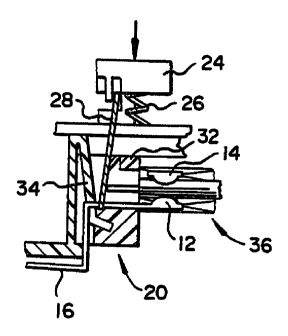
The GFCI receptacle of the present
invention includes an improved trip/reset mechanism,
generally indicated at 10 in the drawing figures, for
resetting a pair of line and neutral movable contacts
12 to closed circuit positions respectively engaging
ZO line and neutral fixed contacts 14, as seen in FIGURE
1(e), and for tripping the movable contacts to open
circuit positions in gapped relation with the fixed
contacts, as seen in FIGURE 1(b). The movable
contacts are carried at the free ends of resilient
conductor straps 16 which are sprung downwardly, such
that the movable contacts are normally biased by the
straps to their open circuit positions.
Mounted by the molded plastic case 18 of
the receptacle for reciprocating movement between a
tripped position seen in 1(a) and a reset position
seen in FIGURE 1(e) is a commutator, generally
indicated at 20. As best seen in FIGURE 3, the
commutator includes a cross beam 22 extending
transversely under the straps 16 such that when the
commutator is elevated to its reset position, the
straps are flexed upwardly to draw the movable
contacts 12 into their closed circuit positions.
Also mounted for reciprocation by case 18 is a manual
reset actuator in the form of a pushbutton 24. Reset
compression springs 26 bias the pushbutton to an
elevated, trip-indicating position seen in
Dkt. No. LD-10,369
FIGURE 1(a). Manual depression of the pushbutton
moves it to a depressed position seen in FIGURE 1(d).
An elongated latch in the form of a metallic strip 28
is pivotally connected at its upper end to the
underside of the reset button 24 and depends inwardly
of case 18 toward commutator 20. A catch 30 is
struck from the latch at a mid-length location such
that, upon depression of the reset button to its
fully depressed position, latch 28 descends
sufficiently to permit the catch to latchingly engage
the underside of a transverse latch shoulder 32, an
integrally formed feature of the commutatar.
As an important feature of the present
invention, a separate latch spring 34 is provided to
act against the lower end of latch 28 during its
descension in response to reset button depression 'in
a manner to control its angular orientation.
Specifically, spring 34 asserts a latch setting force
on the latch once its catch clears the vertical face
of the latch shoulder to ensure that the catch swings
into full latching engagement with the underside of
the latch shoulder, as depicted in FIGURE 1(e). When
the reset button is then released, reset springs 26
raise the reset button, latch 28, commutator 20 and
movable contacts 12 in unison. When the movable
contacts engage fixed contacts 14 to assume their
closed circuit positions and thus established the
commutator and reset button in their respective reset
positions. It is thus seen that the reset springs
additionally serve to provide the contact closing
force and the requisite contact pressure for good
circuit continuity. It is also important to note
that, while the reset button is in its reset
Dkt. No. LD-10,369
_g_
21~11~~
position, latch 28 is displaced from spring 34, as
seen in FIGURE 1(e), and thus exerts no forces on the
trip/reset mechanism while the receptacle is in its
circuit closure, reset condition.
As an additional feature of the present
invention, latch spring 34 is beneficially formed as
an integral feature of receptacle case 18. Thus, as
seen in the illustrated embodiment of the invention,
this spring is in the form of a cantilever mounted
leaf spring integrally joined at one end with a
vertical wall feature 35 of the receptacle and
depending to a crooked free end portion 34a fashioned
for engagement with the free end of latch 28.
To trip mechanism 10 in response to a
detected ground fault, the receptacle is equipped
with a solenoid 36 positioned within case 18 and
including a coil 38 surrounding a plunger 40 having a
large diameter body 40a and a reduced diameter,
axially extending actuating pin 40b. A U-shaped
frame 42 maintains the solenoid assembly and includes
a close fitting hole 44 in one leg 42a through which
plunger body 40a can protrude when the plunger
assumes a quiescent return position and a close
fitting hole 46 in its other leg 42b through which
actuating pin 40b extends. When the solenoid coil is
energized, the plunger is magnetically propelled
leftward to an extended position established by
engagement of the plunger body against the inner side
of frame leg 42b.
In accordance with an important feature of
the present invention, it will be noted that the trip
Dkt. No. LD-10,369
-g-
21~~.~ ~~~
solenoid does not include a return spring for
normally biasing plunger 40 to the rightward return ,
position. Thus the trip solenoid is not required to
generate additional magnetic force to overcome any
spring force brasing the plunger and/or latch to
reset positions. Thus the trip solenoid can be
reduced in size and cost.
In accordance with an additional feature of
the present invention, latch spring 34 is
advantageously utilized to restore trip solenoid
plunger 40 to its return position from its
trip-initiating extended position. When reset button
24 is depressed to reset the receptacle, the latch
spring eventually pivots latch 28 rightward to set
catch 30 in engagement with shoulder, and, in the
process, the latch engages the tip of actuating pin
40b to drive plunger 40 rightward to its return
position. Thus the latch spring serves dual
purposes, to wit, as a latch setting spring and as a
trip solenoid plunger return spring.
Reviewing the operation of trip/reset
mechanism 10, to reset the receptacle from its
tripped condition of FIGURE 1(a), reset button 24 is
manually depressed. As latch 28 descends, catch 28
runs against the vertical face of latch shoulder 30
as seen in FIGURE 1(b). As the reset button achieves
its depressed position, the lower, free end of the
latch engages and flexes latch spring 34 to a charged
condition, as seen in FIGURE 1(c). Once catch 28
clears the latch shoulder vertical face, the latch
spring discharges to set latch 28 with the catch in
full latching engagement with the underside of latch
Dkt. No. LD-10,369
-10-
21~~.~ ~6
shoulder and also to restore solenoid plunger to its
return position, all as illustrated in FIGURE 1(d).
Note that the movable contacts 12 still remain in
their open circuit positions. When the reset button
is released, the now charged reset springs 26
discharge to drive the reset button, latch, and
commutator 20 upward to bring movable contacts 12 to
their closed circuit positions in engagement with
fixed contacts 14, as seen in FIGURE 1(e). The
receptacle is then reset.
Note that digital pressure on the reset
button cannot hold the movable contacts in their
closed circuit positions in the face of a ground
fault. As seen from FIGURE 1(e), the solenoid
remains free to trip mechanism 10 and thus allow the
movable contacts to spring to their open circuit
positions. If the reset button is held fully
depressed, the mechanism parts assume their positions
of FIGURE 1(d), wherein the movable contacts are in
2p their open circuit positions. Again note that latch
spring 34 is fully relaxed and no longer engaging
latch 28 while the receptacle is reset. Thus, this
spring exerts no force on mechanism 10 as it stands
ready to respond to a ground fault.
With the GFCI receptacle residing in its
in-service, reset condition of FIGURE 1(e), to
execute a ground fault trip function, solenoid coil
38 is energized to magnetically drive plunger 40
leftward to impact its actuating pin 40b against
latch 28 at location below catch 30. In response,
the latch is swung leftward to disengage catch 30
from latch shoulder 32, as illustrated in FIGURE
Dkt. No. LD-10,369
-11-
21~3~.~.~
2(a). Note that the crooked free end portion of
latch spring 34 is displaced below the lower end of
latch and thus is clear of this leftward, unlatching
motion. With unlatched commutator 20 disconnected
from reset springs 26, the movable contacts are no
longer held in their closed circuit positions, and
thus resilient straps 16 can discharge to spring the
movable contacts to their open circuit positions.
The GFCI receptacle thus assumes the tripped
condition of FIGURE 1(a).
It is seen that the objectives set forth
above, including those made apparent from the
foregoing Detailed Description, are efficiently
attained, and, since certain changes may be made in
the construct set forth without departing from the
present invention, it is intended that matters of
detail be taken as illustrative and not in a limiting
sense.