Note: Descriptions are shown in the official language in which they were submitted.
- 2101 404
M13THOD AND APPARATU8 FOR WELDING BAG8 TO RING8
The invention relates to a method and apparatus for forming
plastic articles. Specifically, the invention relates to a
method and apparatus for welding a semirigid bead to two
sheets of plastic film.
The invention includes an apparatus for welcling a reinforcing
member to a bag-like means. The apparatus includes at least
one hollow mandrel, the hollow mandrel has an outer surface
with an annular groove for holding the reinforcing member.
The apparatus has a means for applying a closed end of the
bag-like means into the hollow mandrel and an open end of the
bag-like means over the hollow mandrel at the outer surface
with the annular groove for holding the reinforcing member.
The apparatus, also, includes a means for welding the
reinforcing member to the bag-like means.
The invention is, also, a process of producing collapsible
bag-like means having the following steps. Placing a
rein~orcing member into an annular groove on an outer surface
of at least one hollow mandrel first occurs. Opening an open
end of the bag-like means with a means for opening having a
gas injector means for injecting gas into the open end of the
bag-like means follows. Gripping the opened end of the bag-
lik~ means at a plurality of sites on a cirsumference of the
open end of the bag-like means follows. Extending the open
end of the bag-like means occurs. Applying a closed end of
the bag-like means into the hollow mandrQl and the open end o~
the bag-like means over the hollow mandrel at the outer
sur~ace with an annular groove for holding the reinforcing
member follows. Lastly, welding the reinforcing member to the
bag~ e means is performed.
The invention can be performed in various ways and one
specific embodiment will now be described by way of example
with refer~nces to the accompanying drawings in which:
. . ,~ : ~
. ,: . ~ , ~
- 21~140~
Figure 1 - is a general arrangement view of apparatus ~ -
according to the invention;
Figure 2 - shows in more detail an 0-ring pick up
arrangement;
Figure 3 - shows a bag-like means abou~ to descend down
a chute to an 0-ring weld statisn;
Figure 4 - shows the bag-like means during its descent;
Figure 5 - shows the welding head about to move into
position to weld the ring to the bag-like
means; ::
Figure 6 - shows the welding head in position;
Figure 7 - shows the completed bag-like means ready for
removal;
Figure 8 - shows the plan view a gripper finger
assembly;
Figure 9 - is a side view of Figure 8; and ~ ;
Figure 10 - is a detail view of a gripper finger. .~
Figure l illustrates a general arrangement and the numbers : .
shown in the arrows correspond to the arrangement shown in
~igures 2 to 7 described more fully below. In Figure 1, there
is shown at 10 a series of bag-like means attached to backing
paper and as described in the Applicant's co-pending U.K. .
Patent Application
No. 92 1602303.
Figure 2 illustrates an 0-ring pick head 11. The 0-ring pick :
head 11 is arranged to pick an 0-ring from the top of a stack ~:
of 0,rings in an 0-ring feeder tube 12. The O~ring pick head
in this position is shown in dashed or broken lines and mo~es
downwardly on the top of the stack of 0-rings. An 0-ring
gripper 13 releases a single o-ring and the 0-ring pick head
11 then has suction applied to it. The section applied to the -`
0-ring pick head 11 causes the o-ring to be sucked or pulled
by a vacuum into a corresponding groo~e in the underside of
the 0 ring pick head 11. The 0-ring gripper 13 contacts and
retains the remaining 0-rings on the tube. The arrangement is
.............. . . . . . _ .. ... . . . . , . . . . _ _ _ _ .
2 1 ~
such that the O-rings are raised upwardly so that the O-ring
gripper 13 can release the O-rings one at a time.
When the O-ring pick head 11 has lifted the top ring, the 0-
ring pic~ head 11 then rotates so as to be over the first
position of a four position rotary turntable 16. The four
positions of the rotary turntable 16 are indexed at 90~ to one
another.
In the first position t the O-ring pick head 11 moves
downwardly to press an O-ring into an annular groove 17 in a
pot 18 located on the rotary turntable 16. The pot 18 is open
at both ends in the preferred embodiment. Suction is then
applied to the annular groove 17 at the top of the pot 18. At
the same time, the suction is terminated from thP O-ring pick
head 11 and a supply of compressed air is supplied through the
O-ring pick head 11 to assist in transferring the O-ring from
the O-ring pick head 11 to the pot 18 on the rotary turnt~ble
16. Sensor means (not shown) can be pre~ent for verifying the
pr~sence of an O-ring on the annular groove 17. If no o-ring
is on the annular groove 17, the O-ring pick head 11 returns
to transfer another o-ring. When an O-ring has been
satisfactorily placed in the annular groove 17 at the top of
the pot 18~ the O-ring pick head 11 swings away to return to
the position above tbe O-ring feeder tube 12 in preparation
for the start of another cycle.
The rotary turntable 16 rotates 90 to transfer the pot 18
having an O ring to the "bag and O-ring welding station". At
the bag and o-ring welding station, a bag-like means is
supplied. The ~ag-like means, as shown at 10 in Figuxe ll are
adhered to a backing paper and are spaced apart from one
another. The bag-like means are adhered along the edge of
their open end to the backing paper an~ are open at their
right hand sides (according to the embodiment shown in Figure
1) so as to ~orm an entrance to each bag-like means. An eight
finger gripper assembly 19 (explained in detail below) is
adapted to grip the open end of a bag-like means.
: . . . . . .
-: - . ~ : . ~ :
: :
.
2~01~
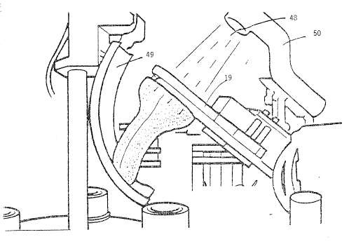
Figures 3 and 4 illustrate the gripper assembly 19 with a bag-
like means attached thereto. In order to arrive at this
position, the gripper assembly 19 is pivoted into a position
approximately 10 past the vertical. The backing paper with
an attached bag-like means is indexed or moved into a curved
trough. The curved trough bends the two plies of plastic film
of the bag-like means so that the lower layer of film, that is
adhered to the backing paper, is stretched about the perimeter
of the curved trough. The upper layer of plastic fiim is
puckered or rippled. The rippled separation between the two
plies of plastic film opens the bag-like means. A high
pressure blast of air is applied to the open end of the bag-
like means to inflate the bag-like means and the gripper
assembly 19 pivots forward approximately 10 to place the
rollex fingers just inside the mouth of the inflated bag-like
means. A double acting twin rod cylinder ~not shown) dri~ves
the actuator plate 43 downwardly and as described below. The
roller fingers assume a circular shape and in so doing grip
and stretch the mouth of the bag-like means causing the bag-
like mean~ to release from the backing paper.
Bag-like means strip air jets direct high pressure gas or air
to ensure that the nose or closed end of the bag-like mPans is
also r~lea~ed ~rom the backing paper. With the bag-like means
still inflated, the gripper assembly 19 pivots forward and the
nose of th~ bag-like means is guided into and slides down a
pivoted curved ~uide chute 49 and into the pot 18 on the
rotary turntable 16 with the O-ring positioned in the annular
groove 17. During this movement of the gripper assembly 19,
air is continuously supplied by an air jet 48. The force of
the air jet 48 pivots with the gripper assembly 19 to keep thP
bag-like means inflated. The guide chute 49 then pivots back
to make room for a weld head 51, shown in Figure 5, to move
into position by pivoting from the side and then moving
downwardly onto the top of the pot 18.
The weld head 51 then presses down through the hole in the
: , .
back of the gripper assembly 19 formed by the movement of the
arms and fingers trapping the plastic film of the stretched
bag-like means between a heated plate and the 0-ring beneath.
Welding of the plastic film to the O-ring is performed for a
short time of about 0O3 seconds at a temperature of about
140C + or -10C. The bag-like means is located over the pot
1~ such that the plastic film of the bag-like means overlaps
and descends down the outside of the pot 18.
Figure 6 illustrates the position of the elements during the
welding procedure. The gripper assembiy î9 i~ lowered sti~l
furth~r. The further lowering of the gripper assembly 19
assists in stripping the annulus of excess film formed by the
overlap of plastic film over the outer periphery of the
O-ring and pot 18. The heat of the welding procedure causes
weakness in the plastic film so that the gripper fingers can
easily strip the surplus plastic film and a neat weld is
formed without any surplus plastic film attached to the weld.
The weld head 51 then lifts and pivots back to the side of the
machine and the gripper assembly 19 begins to pivot back
towards the rest position. At approximately 45 the gripper
assembly l9 pauses and the curved guide chute 49 pivots
forward to shield and protect the recently welded bag-like
means in the rotary turntable 16. The double acting twin rod
cylinder then lifts the actuator plate 43 causing the gripper
finger~ to con~ract and release the bag-like means. While
this proc~dure is occurring, high velocity air jets cause the
annulus of excess film to be blown away from the pot 18 and
deposited to scrap. The gripper assembly 19 then complet~s
the return to the initial position of about 10 past the
vertical.
The four position rotary turntable 16 then moves 90 to a
spare station and then through a ~urther 90 taking thP newly
formed bag-like ~eans to a product removal station. At the
product removal station, a vacuum through the annular groove
. _ . . . . . , ....... . . . . . . . . .......................... _ _
~ '. : :-~: :, .
; .. ~ , .
2 ~ 0 ~
17 of the pot 18 is terminated. A product rem~val haad 52
holds the welded product and pivots through a 180 arc. A
vacuum is initiated through an annulus 53 on the product
removal head 52, thus, enabling the product removal head 52 to
pick the newly formed welded bag-like means Erom the rotary
turntable 16. The welded bag-like means and removal head 52
rotate through a 180 arc so that the welded bag-like means
can be inverted under a transfer tube. The welded bag-like
means is then inflated and the vacuum through the annulus 53
to the product removal head 52 is terminated to cause the
welded bag-like means to be launched up the transfer tube.
The welded bag-like means is pushed by various air jets along
the transfer tube 54 and into platens (not shown). The
platens can be used to transfer the welded bag-like means to a
testing station.
Figures 8, 9, and 10 illustrate the gripper assembly l9 in
detail. The gripper assem~ly 19 comprises two fixed finger
rollers 20 and two sets of movable finger rollers 21, 22, 23,
and 24 which are mounted on the ends of two sets of arms on
each side o~ a center line running through the gripper
assembly 19. Each set has arms 25, 26, and 27 with pins 30,
31, and 32 extending through slots 33, 34, and 35 in a cam
plate 36. The lower ends of the arms are connected by further
pins 37, 38, and 39 through slots 40, 41, and 42 through an
actuator plate 43. The actuator plate 43 is movable betwsen
upper and lower positions as shown in the "split views" of the
left and right hand sides, respectively, of Figure 8.
The lower pin 24 is mounted on a rod which is directly
connected to the actuator plate 43. Each of the gripper
fingers have rollers 44 and these can be seen in FigurP 9.
Figure 9 illustrates the rollers 44 mounted on a fixed pin 45.
The ~ixed pin 45 i~ ~ounted on the end of the respective arm
and ha~ an enlarged head 46. The enlarged head 46 serves to
retain a rollex ~leeve 47. The roller sleeva 47 is rotatable
o~ the pin 45. The roller sleeve 47 has an enlarged shoulder
~ .
'
- 2 1 ~
48 at its outer end. In operation the gripper fingers move
from a first position where they are all grouped together into
a second position where they form a circular shape by caused
the cam plate or actuator plate 43 moving downwardly.
The invention includes a process for weldi~g a reinforcing
member to a bag-like means. The process involved placing a
reinforcing member into an annular groove on an outer surface
of at least one hollow mandrel. Then, opening an open end of
the bag-like means with a means for opening having a gas
injector means for injecting gas into the open end of the bag-
like means is performed. Gripping the opened end of the bag-
like means at a plurality of sites on a circumference of the
open end of the bag-like means occurs. Extending the open end
of the bag-like means and applying a closed end of the bag-
like means into the hollow mandrel and the open end of the
bag-like means over the hollow mandrel at the outer surface
with an annular groove for holding the reinforcing member is
performed. Welding the reinforcing member to the bag-like
member follows.
The process can further comprise ejecting the welded bag-like
means from the mandrel. The process step of gripping can be
performed by a plurality of pron~s. The prongs are
positionable within the open end of the bag-like means at
individual sites on the circumference of the open end of the
bag-like means. The step o~ extending the open end of the
bag-like ~eans can be performed by a cam member whereby
operation o~ the cam member positions the prongs in one of two
conditions~ The two conditions are a first condition wherein
the prongs are gathered together in a substantially }inear
position ~or insertion into the opened open end of the bag-
like ~eans. A second condition can be one wherein the prongs
are separated from one another to extend the open end of said
bag-like means.
'"
:. . :
, ,:
~: .`.,: ,.; ' '