Note: Descriptions are shown in the official language in which they were submitted.
~ ;~
2~ 0~72
REFERENCE TO RELATED APPLICATI~NS
This is a continuation-in-part of copending application
U.S. Serial No. 07/818,000, filed December 30, 1991, which is a
continuation of U.S. Serial No. 07/031,023, filed March 27,
1987, now abandoned.
FIELD ~F THE INVENTION
The present invention relates to solid phase assays for
analytes, in particular to specific binding assays employing
capillary flow of reagents and/or sample in a porous solid
support.
BACKGROUND OF THE INVENTION
Specific binding assays such as immunoassays have been
found to be of great value in a variety of clinical and
research applications due to the specificity of the binding
between ligand and receptor. Many different protocols and
formats for such assayæ have therefore been developed, one of
which involves conducting the binding assay on a piece of
porous material which is usually in the form of a strip. This
type of assay takes advantage of the capillary properties of
the porous material to sequentially bring reaction components
into contact with each other. This is often accomplished by
positioning reaction components at predetermined locations
along the strip so that liquid applied to one end moves by
capillary migration along the strip, contacting the other
reaction components in the desired sequence. Presence of an
analyte is generally determined by detecting the signal from a
detectable label included in the binding reaction between
ligand and receptor.
,~ .
. . .
,: . . ~.~
.
. : ~ .
2 ~ 7 2
Examples of immunoassays using these principles, often
referred to as immunocapillary or immunochromatographic assays,
can be found in the disclosures of WO 87/02774, EP 0 306 772,
U.S. Patent No. 4,094,647, U. S. Patent No. 4,999,285, U.S.
Patent No. 4,16~,146, GB 2 204 398, U.S. Patent No. 4,943,522,
U. S. Patent No. 5,037,736, U. S. Patent No. 5,075,078, U. S.
Patent No. 5,096,837 and C. Glad and A. O. Grubb, Analytical
Biochemistry, 85: 180-187 (1978).
SUMMARY OF THE INVENTION
The present invention provides a porous solid support
having a first portion which is contacted with a sample
suspected of containing the analyte to be detected. Analyte
which is present in the sample flows through the capillaries of
the solid support and combines with a tracer which is
reversibly bound to the solid support. The mixture of analyte
and tracer is transported by capillary flow through the
material of the solid support to a second portion where they
contact and bind to an immobilized binder which binds
specifically to 1) the analyte or 2) the analyte and the
tracer. Unbound tracer moves through the second portion and
into a third portion of the solid support by continued
capillary flow. The third portion may serve only to receive
materials not bound in the second portion (e.g~, as in a
sandwich assay) or it may contain additional reagents for
detection of the unbound tracer (e.g., as in a competitive
assay).
In the present preferred embodiment of the invention,
the sample is applied to the first portion of the solid support
and flows through the first portion into a separate portion
containing tracer, thereby combining analyte which may be
present in the sample with the tracer. Optionally, the
~ ......
.
, .
2 ~ 7 2
combined analyte and tracer may then flow out of the tracer
portion into an additional mixing portion of the solid support
prior to being transported by capillary flow into the region of
the solid support containing the second portion. This optional
additional portion allows further mixing of the analyte and
tracer and a period of incubation to allow binding. The third
portion of the preferred embodiment includes an indicator zone
containing a dye which is transported by the advancing fluid
front to a position on the solid support where it can be viewed
as an indication that the assay is complete.
DESCRIPTION OF THE DRAWINGS
Fig. 1 is a perspective view of a representative device
according to the invention.
Fig. 2 is a sectional view of a representative device
taken along line 2 of Fig. 1.
Fig. 3 is a top plan view of the solid support showing
placement of the openings in the upper section of the housing.
Fig. 4 is a top plan view of the solid support after
successful completion of a positive assay.
Fig. 5 is a top plan view of a representative device
showing an successfully completed positive assay.
DETAILED DESCRIPTION OF THE INVENTION
The present invention is an embodiment of the invention
disclosed in copending application U.S. Serial No. 07/818,000
~U.S. Patent No. ~, the disclosure of which is hereby
incorporated by reference. The present inventio~ provides a
: .
~7
: - ; . ., ' ' -
. - .
- ' ~ ' '
'' . ,, " '~"
- , .
2~ 2
preferred embodiment which represents a particular combination
of certain of the specific structural and functional features
of the solid support previously disclosed. In brief, the
sample is applied to the first portion of the solid support
with the solid support in an essentially horizontal position.
The tracer portion is separate from the first portion and
placed relative to the first portion such that fluid applied to
the first portion flows vertically through the first portion
and enters the tracer portion, after which the tracer and
analyte are transported laterally by capillary flow to the
second portion. The third portion of the preferred embodiment
contains an additional feature for indicating that the
capillary flow of the fluid (i.e., the fluid front) has
advanced to a predetermined completion zone on the solid
support, signalling that the assay is complete.
The region of the solid support containing the first
portion comprises a macroporous material capable of absorbing a
fluid sample applied to its surface. The sample passes through
the capillary channels of the porous first portion into a
separate tracer portion with which it is in fluid
communication. Materials suitable for use in the first portion
include porous polyethylene (e.g., POREX available from Porex
Technologies, Fairburn, Georgia), glass fiber, rayon, nylon and
cellulosic materials such as paper. Porous polyethylene is
particularly preferred. Most preferably, the first portion
comprises a layer having an upper and a lower surface. The
sample is applied to the upper surface of the first portion and
passes through it in a direction substantially perpendicular to
the plane of the upper surface, exiting through the lower
surface into the tracer portion. The first portion functions
primarily as a filter for physical removal of particulate
matter such as cells and debris which may be present in
biological samples. When functioning only as a filter, the
2 ~ 2
first portion may consist only of the macroporous materiai.
However, reagents may also be added to the first portion as
re~uired for the assay. These reagents may be impregnated in
the macroporous material of the first portion and include, for
example, buffers and detergents.
The tracer portion is similarly comprised of a
macroporous material such as porous polyethylene, glass fiber,
rayon, nylon, or cellulosic materials such as paper. The
tracer portion preferably comprises porous polyethylene. The
tracer portion is in fluid communication with the first portion
and absorbs sample fluid as it exits from the first portion.
Preferably it is also a layer which has- an upper surface
contacting the lower surface of the first portion and flow of
fluid through the capillary channels of the tracer portion is
in a direction substantially perpendicular to the plane of its
upper surface. The tracer portion further includes a tracer
which comprises a detectable label conjugated to 1) a ligand
for the analyte, 2) the analyte or 3) an analyte analog. A
ligand for the analyte is a molecule which specifically
recognizes and binds to the analyte, i.e., the ligand and the
analyte are a specific binding pair. Many such ligands are
known in the art, for example antigens and antibodies, enzymes
and their substrates, carbohydrates and lectins, and avidin or
streptavidin and biotin. For use in the present embodiment of
the invention, antibody and antigen ligands are preferred.
The tracer is supported on or in the tracer portion of
the solid support such that when fluid from the first portion
contacts the tracer portion the tracer and analyte are
transported together out of the tracer portion by capillary
flow into the second portion. That is, the tracer is
immobilized in the tracer portion but is reversibly bound and
upon wetting of the tracer portion by sample fluid the tracer
'
.
.. . ..
- ~ ~ -
-
- 2~Q1~72
is released. The detectable label component of the tracer may
be any detectable label known in the art for use in specific
binding assays, particularly immunoassays. These include
radioisotopes, fluorescent dyes, enzymes capable of reacting to
produce colored products, visible dyes, etc. Methods for
conjugating these labels to ligands and detecting the signals
they produce are well known in the art.
Particulate detectable labels are preferred for use in
the present embodiment of the invention. Suitable particles
include particles of polymers (e.g., latex or polystyrene),
sacs, liposomes, metallic sols (e.g., colloidal silver or
colloidal gold~ or polymeric dyes. To form the tracer, such
particles are derivatized to include the detectable label,
usually by formation of a chemical bond using methods known in
the art for this purpose. In the case of sacs and liposomes,
the label may also be entrapped in the vesicle. The particle
and its associated label may be chemically conjugated to the
ligand component of the tracer. Alternatively, polymer
particles, polymeric dyes and metal particles may be coated
with the ligand component of the tracer, e.g., as described in
U.S. Patent No. 5,096,837. Most preferred for use as a
detectable label in the present embodiment of the invention are
polymeric particles impregnated with a visible absorbing dye,
particularly 0.4-0.5 micron latex microparticles such as BLUE
DYED LATEX available from Bangs Laboratories, Indianapolis,
Indiana.
The present embodiment of the invention further
includes an optional mixing portion in fluid communication with
the tracer portion. The mixing portion also comprises a
macroporous material as disclosed above for the first and
tracer portions and is preferably porous polyethylene. Fluid
passing through the first and tracer portions flows into the
. .
,:
:; :
: ~ :
2 ~ 7 2
mixing portion prior to being transported out of the mixing
portion into the segment of the solid support containing the
second portion. The mixing portion facilitates mixing of the
analyte with the tracer prior to capillary flow out of the
mixing portion into the second portion. In addition, in
sandwich assays the mixing portion provides a period of
incubation for binding of analyte and tracer prior to contact
of the analyte/tracer complex with the second portion.
Preferably the mixing portion is also in the form of a layer
with an upper surface in fluid communication with the lower
surface of the tracer portion.
Fluid passing through the tracer portion enters the
mixing portion through its upper surface and flows in a
direction essentially perpendicular to the plane of the mixing
portion layer, exiting through the lower surface. The mixing
portion is in fluid communication with the segment of the solid
support containing the second portion and fluid transport
proceeds from the mixing portion into the second portion by
capillarity. If the mixing portion is not included in the
assay device, the tracer portion is in direct capillary fluid
communication with the segment of the solid support containing
the second portion.
The segment of the solid support containing the second
portion comprises an absorbent microporous material. The
microporous material serves to wick fluid from the preceding
portions into the second portion by capillarity. That is, the
fluid mixture of analyte and tracer is transported by capillary
flow from the tracer portion or the mixing portion into the
microporous material and continues to be transported within the
microporous material into contact with the binder of the second
portion. Suitable microporous materials for use in this
segment of the preferred assay device include filter paper,
2 ~ 7 2
chromatographic papers, glass fiber, crosslinked dextran, nylon
and nitrocellulose. Nitrocellulose is most preferred because
the binder of the second portion can be easily immobilized on
this material without requiring covalent attachment.
While not required, most preferably the segment of the
solid support comprising the absorbent microporous material is
positioned such that the direction of capillary flow within it
is substantially perpendicular to the direction of flow through
the preceding portions, as shown in the accompanying Figures.
This provides an assay which can be performed with the assay
device in a horizontal rather than a vertical position,
eliminating the need to hold the device during the performance
and reading of the assay. In addition, the most preferred
assay device includes all of the preceding portions, including
the optional mixing portion.
The binder of the second portion is a ligand or
receptor which specifically binds to a complementary binding
pair member which is 1) the analyte or 2) the analyte and the
tracer depending on whether the assay is performed in a
sandwich or a competitive assay format. Many such
binder/complementary binding pair member pairs are known in the
art, and they include antibodies and antigens, lectins and
carbohydrates, enzymes and their substrates, and specific
binding proteins such as biotin and avidin or streptavidin.
For use in the assay of the present invention, antigens or
haptens and polyclonal or monoclonal antibodies are preferred
binders for the second portion. The selection of antibody or
antigen for the second portion binder depends on the nature of
the analyte being detected, i.e., whether the analyte is itself
an antigen or an antibody. When the analyte to be detected is
an antibody the binder in the second portion may be the antigen
specifically recognized and bound by that antibody.
:
.. ~ . . . :
21~1 d~
Alternatively, the antibody analyte may be bound in the second
portion by a suitable anti-antibody antibody. Conversely, when
the analyte to be detected is an antigen or hapten the binder
in the second portion may be an antibody directed against that
antigen.
The binder is immobilized on the microporous material
in the second portion such that it is not removed from the
second portion by the capillary flow of fluid through the
second portion. That is, the binder is nondiffusively bound to
the microporous material and remains immobilized in the second
portion when the second portion is wetted by the fluid
containing analyte and tracer. Such immobilization may be
accomplished by covalent attachment of the binder to the
microporous material using methods known in the art.
Alternatively, satisfactory noncovalent attachment is possible
when nitrocellulose is the microporous materiaI. For this
reason, nitrocellulose is the preferred material, as it allows
for simpler methods of attachment of the binder. The binder
may therefore be spotted or printed on the second portion when
nitrocellulose is used, and is preferably applied in a defined
pattern such as a "plus" sign, a checkmark or a geometric
figure (e.g., a circle, square or triangle). As the fluid
containing the analyte and tracer flows into the second portion
the analyte and tracer become bound to the binder in the second
zone and are immobilized there.
If a defined pattern of binder is immobilized in the
second portion a second pattern of a second binder may also be
applied at a location on the solid support which is adjacent to
the second portion binder such that the two binders are
contacted by the advancing fluid front under similar
experimental conditions. This second pattern may be used as a
positive control area to assure that the assay is functioning
1~
,
, : , ~ . , . ; ., ~:
..
. . .,, ., . -. . . . .
" ' : '~ ' . '
2191~7~
properly, containing either an antigen or antibody as
appropriate. For example, if the assay is designed to detect
an antigen analyte, the second pattern ma~ comprise the antigen
to be detected. If the assay is designed to detect an antibody
analyte, the second pattern may comprise an anti-antibody.
Alternatively, the binder of the second pattern may be
unrelated to the analyte being detected, for example an
anti-hapten antibody which binds a labeled hapten included in
the tracer portion. Examples of suitable haptens include
biotin, DNP and benzoic acid, with the corresponding antibodies
being present in the second pattern of the second portion.
After contacting the second portion, the fluid
continues to move by capillary migration through the
microporous material, through and past the second portion and
into the third portion. That is, the third portion is in
capillary fluid communication with the second portion. The
third portion comprises the area of the microporous support
which receives fluid from the second portion. In a competitive
assay format, the third portion may contain a substance for
detecting tracer which was not bound in the second portion. In
a sandwich assay format the third portion usually functions
only to receive the fluid containing materials which were not
bound in the second portion, i.e., it does not contain any
additional reagents related to detection of analyte.
Preferably, the third por~ion further includes an indicator
zone of visible, water soluble dye such as Erythrosin B,
Safranin O or Phenol Red applied to the support in a defined
area such that the dye is reversibly bound to the support.
When the fluid front has traversed the second portion and
entered the third portion it flows through the indicator zone
and the dye is carried by the fluid from its original position
on the microporous material to a second position (the
completion zone) where it can be visually detected as an
ll .
..
-
.
.. ~ .
- 2 ~ 2
indication that the fluid front has passed through the first,
tracer and second portions and the assay is complete. If the
third portion includes reagents for detection of unbound
tracer, the indicator zone is located in an area contacted by
the fluid front after contact with the reagents.
In an alternative embodiment, the tracer is reversibly
immobilized on the microporous material in an area thereof
defining the tracer portion. The tracer portion is placed
between the first portion and the second portion containing the
binder. The first port;.on is in direct fluid communication
with the microporous material. A sample applied to the first
portion is wicked into the microporous material where it
contacts and mixes with:the tracer. After flowing through the
tracer portion the fluid continues to move by capillarity into
the second portion for interaction with the binder. This
embodiment has particular advantages in assays for antibody
analytes which employ an antigen tracer, as less tracer can be
used with resulting cost savings.
The most preferred assay protocol for the present
preferred embodiment of the invention is a sandwich assay for
detection of an antibody or antigen analyte. In a sandwich
assay, because the tracer/analyte complex is immobilized and
detected in the second portion, the binder is usually present
in excess to ensure that substantially all of the complex is
bound. Detection of the intensity of the label signal may then
be used as a qualitative, quantitative or semiquantitative
indication of the amount of analyte present.
By way of example, in a sandwich assay if an antibody
is the analyte to be detected, the ligand portion of the tracer
may be an antigen or hapten recognized and bound by the
antibody analyte. Antigen or hapten may also be the binder
/~ :'
. .
.: . . .. . , . . .. , - ~ ~
.. . . . , . : .. ~ :
..
2 ~ 7 2
immobilized in the second portion. One s~illed in the art wiil
recognize that in order to have binding in the second portion
when the binder and tracer are hapten or analyte in a sandwich
assay for detection of antibody, the tracer will be present in
an amount which is below what would saturate the analyte
binding capacity of the antibody. Such routine adjustments in
the quantity of reagents are within the ordinary skill in the
art. Alternatively, either the tracer or the binder may be an
anti-analyte (Ab) antibody.
To perform the sandwich assay, a sample suspected of
containing the antibody is applied to the first portion and
allowed to move by capillary migration through the first
portion into the tracer portion where it mixes with the labeled
tracer. If present, the analyte antibody binds to the ligand
component of the tracer. As the fluid moves through the tracer
portion the tracer is transported out of the tracer portion
with the fluid. Most preferably the mixture is transported out
of the tracer portion into a mixing portion which allows
additional time for binding of the antibody and tracer prior to
contact with the microporous material and the second portion.
In the second portion the binder binds to the antibody/tracer
complex and immobilizes it in the second portion. The label
component of the tracer can then be detected in the second
portion to indicate a positive assay result. If the assay is
negative, i.e., there is no antibody present in the sample, no
antibody/tracer complex will be bound in the second portion and
no tracer will be detected. The fluid front containing any
unbound antibody, tracer and antibodyJtracer complex continues
to move by capillarity through the second portion into the
third portion where it contacts the dye localized in the
indicator zone. The fluid front carries the dye from the
indicator zone to the completion zone indicating that the fluid
front has passed the second portion and the assay is compIete.
13
... . , : ., .
~: . . . , -
.. . .
.
. . . :
7 ~
Representative examples of antibody analytes which may be
detected using this method are antibody to human
immunodeficiency virus (HI~), antibody to rubella, antibody to
cytomegalovirus, antibody to Epstein Barr Virus (EBV) and
antibody to the Lyme disease pathogen Borrelia burqdorferi.
Conversely, a sandwich assay in which an antigen
analyte is to be detected may employ a tracer comprising an
antibody which specifically recognizes and binds to the antigen
being detected. The binder in the secGnd zone may be a second
anti-antigen antibody which recognizes and binds to an epitope
on the antigen which is not the same as the epitope bound by
the tracer antibody. Otherwise, the sandwich assay for antigen
is performed essentially as described above for detecting an
antibody analyte. ~epresentative examples of antigen analytes
which may be detected using this method are Group A
Streptococcus antigens, human chorionic gonadotrophin (HCG),
luteinizing hormone (LH) and Chlamydia antigens.
The assay may also be performed in a competitive assay
format. In this embodiment the analyte (either antigen, hapten
or antibody) is mixed with a tracer comprising a ligand which
is capable of competing with the analyte for binding in the
second portion. The binder is therefore usually present in an
amount which will bind less than the total amount of analyte
and tracer when analyte is present but is sufficient to bind
essentially all of the tracer when analyte is absent. This
allows unbound traaer to be detected in the third portion when
analyte is present. In general, if the analyte is an antibody
the ligand component of the tracer is the same antibody, but
the tracer antibody may be any antibody which recognize~ the
same epitope as the analyte antibody or competes with it for
binding to the binder. If the analyte is an antigen or hapten
the ligand component of the tracer is usually the same antigen
lY
. .
'.' ~' , : . . ' ~ ,
,: . . , . - -
.
2 ~ r~ 7 ~
or hapten, but it may also be an analog of the analyte. An
analog of the analyte antigen or hapten includes any
derivatives of the antigen or hapten which are capable of
competing with the analyte for binding to the binder in the
second portion.
For a competitive assay, after mixing with the
appropriate tracer in the tracer portion and, optionally, in
the mixing portion the combined tracer and analyte are
transported by capillary migration in the microporous support
material into contact with the binder in the second portion.
When the analyte is an antibody, the binder is usually the
antigen or hapten recognized by the antibody or an analog
thereof. It is usually an antibody which recognizes the
antigen or hapten when antigen or hapten is the analyte. If an
analog of the analyte is used as the tracer for an antigen or
hapten analyte, the antibody binder also recognizes and binds
to the analog.
The fluid front continues to be transported by the
microporous material through and past the second portion,
allowing competitive binding and immobilization of analyte and
tracer in the second portion. Unbound tracer and unbound
analyte then flow by capillarity into the third portion where
the tracer contacts additional reagents, if required, and ~he
label is detected. For example, if the label is an enzyme
which produces a colored reaction product, the additional
reagents would include the appropriate enzyme substrate.
Labels such as fluorescent dyes, radioisotopes, and absorbing
dyes are directly detectable without further reaction and
usually no additional reagents in the third portion are
required. The advancing fluid front also carries dye from the
indicator zone into the completion zone of the solid support
where it can be visualized, indicating that the fluid has
21~1~72
traversed both the second portion and the reagent-containing
area of the third portion, if present. This serves as an
indication that the assay is complete.
Whether the assay format is a sandwich or competitive
assay, when the tracer label is a dye it is preferred that the
assay method include a step to stabilize color development in
the portion where the tracer label is detected. This is
because in immunocapillary assays continued capillary flow of
fluid into the area where the label is detected allows the
signal from the label to continue developing in intensity.
This signal "drift" may cause a negative result to become a
false positive result over time, or a weak positive signal to
be come a strong posi:tive. At present there is no method
available which stops or stabilizes the signal in an
immunoassay based on capillary migration. It has now been
found, however, that application of a hygroscopic material to
the solid support after addition of the sample inhibits signal
drift and stabilizes signal development for later reading of
the assay result. It is preferable to add the hygroscopic
material to an area of the solid support upstream of the second
portion and most preferable to add it at the site of addition
of the sample.
Hygroscopic materials useful for stabilizing color
development in the present assay include polysodium acrylate
(PSA, available from United Desiccants, Pennsauken, New
Jersey), SEPHADEX (a bead-formed gel prepared by cross-linking
dextran with epichlorohydrin, available from Pharmacia Fine
Chemicals, Piscataway, N.J.), and absorbent cellulose
derivatives such as TR~NSORB cellulosic filters (American
Filtrona, Richmond, Virginia). Most preferred is SEPHADEX
G-50. While not wishing to be bound by any specific theory of
how this aspect of the invention operates, Applicants believe
f~
... ... . . . , . ~
:
:
2 ~ 7 2
that the hygroscopic material stabilizes signal development by
absorbing fluid from the porous support, thus interrupting
capillary flow of fluid and tracer into the portion where label
is to be detected. The selected hygroscopic material may be
applied to the first portion of the solid support either after
the fluid front has traversed the portion where the label is to
be detected or it may be applied substantially immediately
after addition of the sample. This color stabilizing method is
particularly useful when the tracer label includes a visible
dye, such as a dye conjugated to or incorporated in latex
particles.
The materials and reagents described above are
preferably packaged in :the form of an assay device for ease of
use. An example of such a device, to be used in a horizontal
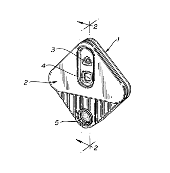
position, is illustrated in Fig. 1. The porous support with
the first, tracer, mixing, second, third and indicator portions
is placed within a housing of a suitable fluid-impermeable
material. Moldable plastics such as polystyrene are preferred,
but other impermeable materials such as glass or metal may also
be used. The housing comprises a lower section (1) and an
upper section (2). The porous support lays in the lower
portion of the housing and is covered by the upper portion
which has a plurality of openings therein. These openings are
aligned with the porous support and provide visual or sample
access to the various portions of the support (3-S). Referring
now to Fig. 2, the sample port opening (5) provides access to
the macroporous material comprising the first zone ~6) and
preferably has raised sides around the opening which form a
well to facilitate application of a fluid sample to the first
zone. The macroporous material comprising the first zone fits
snugly against the interior edge of the sample port such that
sample fluid applied thereto has access to the underlying
tracer portion essentially only by flowing through the first
17
.; . ` : ~, . .~`.
. `:
21~ 72
portion, The macroporous materials comprising the tracer (7)
and optional mixing (8) portions of the support are aligned
with the sample port beneath the first zone such that fluid
flow through the capillaries of these materials is
substantially perpendicular to the plane of the device and the
plane of the first portion.
The microporous material carrying the second portion
(9) contacts the macroporous material comprising the tracer
portion or the mixing portion, if present, and extends within
the housing in a direction substantially perpendicular to the
direction of fluid flow through the first and tracer portions.
Preferably, the microporous material is placed between an upper
layer (10) and a lower layer (11) of a fluid impermeable
material such as polyethylene terephthalate (e.g., MYLAR,
available from Adhesives Research Incorporated, Glen Rock,
Pennsylvania) or polyethylene. The microporous material is not
covered with the fluid impermeable material where it contacts
the tracer or mixing portions so that capillary flow of fluids
in the device is not disrupted. In the sandwich assay device
illustrated, a detection window (4) is provided in the upper
section of the housing aligned with the second portion of the
microporous material and providing visual access thereto. The
detection window allows visualization or detection of tracer
bound to the second zone as shown in Fig. 4 (13), indicating a
positive result in a sandwich assay. In a device for use in
competitive assays, the detection window may be placed in
alignment with the area of the third portion where unbound
tracer can be detected.
The indicator dye (12) is located in the indicator zone
on the microporous support at a position which is contacted by
the fluid after it passes through the second portion.
Alternatively, the indicator dye may be in an area of the
1~ .
'' . ` ' . : `
,
-
.
2 ~ 7 ~
microporous support which is contacted by the fluid after
passing through the second portion and the area of the third
portion where unbound tracer is detected in a competitive
assay. The indicator zone is preferably concealed under the
upper section of the housing and not visible prior to running
an assay using the device. When an assay is run and the fluid
front passes through the indicator zone, the dye is moved by
capillary flow along the support into alignment with a
completion wi.ndow (3) in the upper section of the housing, at
which time the dye becomes visible through the completion
window. This indicates that the fluid front has passed through
all portions of the device required for successful completion
of the assay. Fig. 4 illustrates a completed positive assay in
which the indicator dye (12) has moved into view in the
completion window (3), with tracer immobilized in the second
portion (13) and in the positive control area (14). Fig. 5
illustrates the positive assay of Fig. 4 as it would be viewed
by the practitioner using the intact device.
The follo~ing experimental Examples are provided to
illustrate certain features of the invention but are not to be
considered as limiting the scope of the invention as defined by
the appended claims.
EXAMPLE 1
CONSTRUCTION AND USE OF AN ILLUSTRATIVE ASSAY DEVICE
An approximately 9 ~ 10 mm piece of porous polyethylene
(15-45 ~m POREX) approximately 1.5 mm thick was impregnated
with a tracer comprising anti-HCG antibody labeled with dye
impregnated O.4-0.5 micron latex microparticles (BLUE DYED
LATEX, Bangs Laboratories, Indianapolis, Indiana) to form a
tracer portion. The tracer portion was sandwiched between a
second 9 X 10 mm piece of porous polyethylene and a 9 X l9mm
1~ .
.
~'
.. , ~ ... . . ~.
,
- 21~72 ~
piece of porous polyethylene and the polyethylene stack was
placed on top of a strip of nitrocellulse approximately 9 X 46
mm in size with the bottom edges aligned. The polyethylene
stack and the nitrocellulose were held together with adhesive
backed MYLAR (AS-llO ACRYLIC SYSTEM from Adhesives Research
Inc., Glen Rock, Pennsylvania) placed along the aligned bottom
edge. Approximately 10-1~ mm from the free edge of the larger
piece of polyethylene 1 microgram of anti-HCG antibody in 1
~1 of PBS/5% glucose was spotted on the nitrocellullose in
the shape of a checkmark and allowed to dry. S ~g of HCG in
1 ~1 of PBS were spot~ed in a small dot adjacent to the
anti-HCG antibody checkmark as a positive control area and also
allowed to dry. 1 ~1 of Erythryosin B (Aldrich Chemical Co.,
Inc., Milwaukee, Wisconsin) was placed in a band across the
nitrocellulose about 5 mm above the anti-HCG binder (i.e.,
about 15-20 mm from top edge of the larger piece of
polyethylene). The prepared solid support was then placed in
the lower section of a molded polystyrene housing as shown in
the Figures. The upper section of the housing with openings
aligned with the smaller piece or polyethylene, the anti-HCG
checkmark/HCG dot, and an area of the nitrocellulose downstream
from the band of Erythrosin B was placed over the support and
snapped into place on the lower section.
.
To perform an assay for HCG using the device, five
drops (about 320 ~1) of urine were added to the sample well
and absorbed. After about 1 min. the Erythrosin B indicator
dye appeared in the completion window, indicating completion of
the assay. At that time a blue checkmark appeared in the
detection window, indicating a positive result for HCG. The
blue dot adjacent to the checkmark was also visible as a
positive control. Negative control samples consisted of pooled
negative urine or PBS, and when these were run in the assay
system only a blue positive control dot appeared in the
~0
~.. ....... . . .
:
.
. - : :- , :
. .
'.:. :'
:: :
detection window.
EXAMPLE 2
STABILIZATION OF COLOR DEVELOPMENT
A device similar to the device shown in the Figures for
assaying HCG was used to test methods for stabilization of
color development. The assay was a sandwich assay in which the
tracer and binder comprised anti-HCG antibodies and the tracer
label was BLUE DYED LATEX.
.
Five drops of urine samples containing 250 mIU/ml of
HCG were added to the sample port of the assay devices and the
assay was allowed to r-un until the dye became visible in the
indicator window, indicating the end of the assay. At that
time SEPHADEX G-50 was added to the sample port to fill it.
Control assays were performed in which no SEPHADEX was added to
the sample port. Negative control assays were run with 5 drops
of urine whiah did not contain HCG.
Assay results were scored visually on a scale of l+ to
4+. For positive samples, the color reaction was initially
evaluated as 1-2+. This intensity was maintained for four days ~ -
in the devices which were treated with SEPHADEX. In contrast,
when no SEPHADEX was added to the positive assay devices, the
signal became progressively stronger over four days. -
.
For the negative controls, the initial test result was
negative. However, when no SEPHADEX was added to the assay
device a false positive result developed between 1 and 4 days
after completion of the assay. Devices treated with SEPHADEX
remained negative for four days.
Similar experiments assaying for Group A Streptococcus
~ .
.
. ~ ::: - :
21 ~472
antiqens were performed to test the stabilizing capabilities of
PSA and FILTRONA cellulose filters. In this instance, the
hygroscopic material was added to the sample port substantially
immediately after addition of the sample to the assay device.
The samples were nitrous acid extracts of throat swabs which
tested negative for Group A Strep by the latex test (CULTURETTE
10 MINUTE, Becton Dickinson Advanced Diagnostics, Baltimore,
Maryland).
Throat swabs negative for Group A Streptococcus
organisms were extracted with nitrous acid. Five drops (about
320 ~1) of this extract were added to the sample wells of the
assay devices. As soon as the liquid was absorbed, the
absorbent material (PSA:or TRANSORB) was added to the well. In
control assays, no absorbent was added. Assay results were
monitored visually as l+ to 4+ in the detection window at the
time the indicator dye appeared in the completion window (End
of Assay, "EOA") and 3, 5, and 10 min. later. Samples without
added absorbent showed a significant proportion which drifted
from negative to positive within the experimental time period.
In contrast, samples with added PSA or TRANSORB showed no
increase in false positives.
To determine the effect of color stabilization on
sensitivity of the assay, 5 drops of extracted Group A
Streptococcus antigen were added to assay devices and the
results compared at EOA with and without PSA or TRANSORB. No
detectable difference in sensitivity due to the absorbent was
found.
.~
:
.:
, ' ' ' ' "' ' '